VTV2007003Theral Printer with RFID
TSC Auto ID Technology Co., Ltd.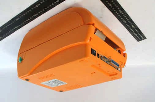
Click to zoom
Application Details
- Equipment Class
- DXX - Part 15 Low Power Communication Device Transmitter
- Date of Grant
- Dec 27, 2007
- Application Purpose
- Original Equipment
- Date of Application
- Dec 23, 2007
- Equipment Note
- Theral Printer with RFID
- Frequency Range
- 13.56000000 - 13.56000000
- Country
- Taiwan
Documents & Files
Document Text
Text extracted from the exhibit documents filed with the FCC. Open a document above to read the original.
Users Manual
DuraLabel Pro 200 / DuraLabel Pro 300 i 1. Introduction.........................................................................................1 2. Getting Started ....................................................................................1 2.1 Unpacking and Inspection............................................................1 2.2 Equipment Checklist.....................................................................1 2.3 Printer Parts...................................................................................3 3. Setup....................................................................................................4 3.1 Setting Up the Printer ...................................................................4 3.2 Loading the Ribbon.......................................................................4 3.3 Loading Label Stock .....................................................................6 3.4 External Label Roll Mount Installation (Option) .........................8 3.5 Peel-off Module Installation (Option)...........................................9 3.5.1 Loading the Paper in Peel-off Mode....................................12 3.6 Cutter Module Installation (Option) ...........................................14 3.6.1 Loading Label in Cutter Mode .............................................17 3.7 Instructions to Top Cover Operation.........................................18 4. Power on Utilities..............................................................................21 4.1 Ribbon and Gap/Black Mark Sensor Calibration ......................21 4.2 Gap/Black Mark Calibration;Self-test;Dump Mode ..............22 4.3 Printer Initialization .....................................................................25 4.4 Black Mark Sensor Calibration ..................................................26 4.5 Gap Sensor Calibration ..............................................................26 4.6 Skip AUTO.BAS...........................................................................26 5. Maintenance ......................................................................................28 5.1 Cleaning .......................................................................................28 6. Troubleshooting................................................................................29 6.1 LED Status ...................................................................................29 6.2 Print Quality.................................................................................30 7. Specifications ...................................................................................31 7.1 Printer Specifications .................................................................31 7.2 Label Stock Specifications.........................................................31 7.3 Ribbon Specifications.................................................................31 8. LED and Button Operation...............................................................33 8.1 LED ...............................................................................................33 8.2 Button Operation.........................................................................33 Update History ......................................................................................36 Contents 1 Compliances CE Class B: EN55022: 1998+A1: 2000+A2: 2003 EN55024: 1998+A1: 2001+A2: 2003 IEC 61000-4 Series EN61000-3-2: 2006 & EN61000-3-3: 1995+A1: 2001 FCC Part 15, Class B This device complies with Part 15 of the FCC Rules. Operation is subject to the following two conditions: (1) this device may not cause harmful interference and (2) this device must accept any interference received, including interference that may cause undesired operation. UL, CUL C-Tick: CFR 47, Part 15/CISPR 22 3 rd Edition: 1997, Class B ANSI C63.4: 2003 Canadian ICES-003 TÜV-GS: EN60950: 2000 1 1. Introduction Thank you for purchasing the Thermal Transfer and Direct Thermal Bar Code Printers. Although the printer takes only a small amount of space, it delivers reliable, superior performance. 2. Getting Started 2.1 Unpacking and Inspection This printer has been specially packaged to withstand damage during shipping. Please carefully inspect the packaging and printer upon receiving the bar code printer. Please retain the packaging materials in case you need to reship the printer. 2.2 Equipment Checklist One printer unit One Windows labeling software/driver CD disk One sample ribbon roll One sample label roll One label spindle (1 inch diameter core) Two label spindle fixed tabs Two 1.5” core adapter One paper core for ribbon rewind spindle Two ribbon supply/rewind spindles One Centronics interface cable One auto switching power supply One power cord One quick start guide If any parts are missing, please contact the Customer Service Department of your purchased reseller or distributor. Options External label roll mount 2 Label spindle (3-inch diameter core) Programmable keyboard Stand-alone LCD keyboard Automatic cutter module Peel off module Internal Ethernet print server External 802.11b/g wireless print server 3 2.3 Printer Parts Fig. 1 Top front view Top Cover Open Lever LED Indicator Feed Button Printer Top Cover Ribbon Access Cover Clear Window 1 2 3 4 5 6 1. USB Interface 2. Centronics Interface 3. RS-232C DB-9 Interface 4. Power Jack 5. Power Switch 6. Rear Paper Guide Fig. 2 Rear view 4 3. Setup 3.1 Setting Up the Printer 1. Place the printer on a flat, secure surface. 2. Make sure the power switch is off. 3. Connect the printer to the computer with the Centronics or USB cable. 4. Plug the power cord into the power supply connector at the rear of the printer, and then plug the power cord into a properly grounded receptacle. Fig. 3 Attach power supply to printer 3.2 Loading the Ribbon The printer will detect if the ribbon is installed after turning on power on and it will set printin…
Text truncated - open the document above for the full version.
Users Manual
TTP-024-50HR Pro / TTP-024-60HR Pro i 1. Introduction.........................................................................................1 2. Getting Started ....................................................................................1 2.1 Unpacking and Inspection............................................................1 2.2 Equipment Checklist.....................................................................1 2.3 Printer Parts...................................................................................3 3. Setup....................................................................................................4 3.1 Setting Up the Printer ...................................................................4 3.2 Loading the Ribbon.......................................................................4 3.3 Loading Label Stock .....................................................................6 3.4 External Label Roll Mount Installation (Option) .........................8 3.5 Peel-off Module Installation (Option)...........................................9 3.5.1 Loading the Paper in Peel-off Mode....................................12 3.6 Cutter Module Installation (Option) ...........................................14 3.6.1 Loading Label in Cutter Mode .............................................17 3.7 Instructions to Top Cover Operation.........................................18 4. Power on Utilities..............................................................................21 4.1 Ribbon and Gap/Black Mark Sensor Calibration ......................21 4.2 Gap/Black Mark Calibration;Self-test;Dump Mode ..............22 4.3 Printer Initialization .....................................................................25 4.4 Black Mark Sensor Calibration ..................................................26 4.5 Gap Sensor Calibration ..............................................................26 4.6 Skip AUTO.BAS...........................................................................26 5. Maintenance ......................................................................................28 5.1 Cleaning .......................................................................................28 6. Troubleshooting................................................................................29 6.1 LED Status ...................................................................................29 6.2 Print Quality.................................................................................30 7. Specifications ...................................................................................31 7.1 Printer Specifications .................................................................31 7.2 Label Stock Specifications.........................................................31 7.3 Ribbon Specifications.................................................................31 8. LED and Button Operation...............................................................33 8.1 LED ...............................................................................................33 8.2 Button Operation.........................................................................33 Update History ......................................................................................36 Contents 1 Compliances CE Class B: EN55022: 1998+A1: 2000+A2: 2003 EN55024: 1998+A1: 2001+A2: 2003 IEC 61000-4 Series EN61000-3-2: 2006 & EN61000-3-3: 1995+A1: 2001 FCC Part 15, Class B This device complies with Part 15 of the FCC Rules. Operation is subject to the following two conditions: (1) this device may not cause harmful interference and (2) this device must accept any interference received, including interference that may cause undesired operation. UL, CUL C-Tick: CFR 47, Part 15/CISPR 22 3 rd Edition: 1997, Class B ANSI C63.4: 2003 Canadian ICES-003 TÜV-GS: EN60950: 2000 1 1. Introduction Thank you for purchasing the Thermal Transfer and Direct Thermal Bar Code Printers. Although the printer takes only a small amount of space, it delivers reliable, superior performance. 2. Getting Started 2.1 Unpacking and Inspection This printer has been specially packaged to withstand damage during shipping. Please carefully inspect the packaging and printer upon receiving the bar code printer. Please retain the packaging materials in case you need to reship the printer. 2.2 Equipment Checklist One printer unit One Windows labeling software/driver CD disk One sample ribbon roll One sample label roll One label spindle (1 inch diameter core) Two label spindle fixed tabs Two 1.5” core adapter One paper core for ribbon rewind spindle Two ribbon supply/rewind spindles One Centronics interface cable One auto switching power supply One power cord One quick start guide If any parts are missing, please contact the Customer Service Department of your purchased reseller or distributor. Options External label roll mount 2 Label spindle (3-inch diameter core) Programmable keyboard Stand-alone LCD keyboard Automatic cutter module Peel off module Internal Ethernet print server External 802.11b/g wireless print server 3 2.3 Printer Parts Fig. 1 Top front view Top Cover Open Lever LED Indicator Feed Button Printer Top Cover Ribbon Access Cover Clear Window 1 2 3 4 5 6 1. USB Interface 2. Centronics Interface 3. RS-232C DB-9 Interface 4. Power Jack 5. Power Switch 6. Rear Paper Guide Fig. 2 Rear view 4 3. Setup 3.1 Setting Up the Printer 1. Place the printer on a flat, secure surface. 2. Make sure the power switch is off. 3. Connect the printer to the computer with the Centronics or USB cable. 4. Plug the power cord into the power supply connector at the rear of the printer, and then plug the power cord into a properly grounded receptacle. Fig. 3 Attach power supply to printer 3.2 Loading the Ribbon The printer will detect if the ribbon is installed after turning on power on and it will set printing …
Text truncated - open the document above for the full version.
Cover Letter(s)
No. 65, Ku Dai Keng St., Hsichih, Taipei 221, R.O. C. Tel: 886-2-2646-2550 FAX: 886-2-26464641 No. 120, Lane 180, San Ho Tsuen, Hsin Ho Rd. Lung-Tan Hsiang, Tao Yuan County 325, Taiwan, R.O.C. Tel: 886-3-407-1718 FAX:886-3-407-1738 Request for Confidentiality Date: Dec. 4th, 2007 American Telecommunications Certification Body, Inc. 6731 Whittier Avenue Suite C110 McLean, VA 22101 RE: Certification Applications FCC ID: VTV2007003 Model: DuraLabel Pro 200; DuraLabel Pro 300; TT024-50HR Pro; TT024-60HR Pro Please be advised that the following information is to be held confidential on behalf of TSC AUTO ID TECHNOLOGY CO., LTD q Block Diagram q Schematics q Product Specification The application contains technical information which TSC AUTO ID TECHNOLOGY CO., LTD deems to be trade secrets and proprietary. If made public, the information might be used to the disadvantage of the applicant in the market place. Thank you for your attention to this matter. Sincerely, ________________ Eddy Hsiung / Director International Standards Laboratory
Cover Letter(s)
No. 65, Ku Dai Keng St., Hsichih, Taipei 221, R.O. C. Tel: 886-2-2646-2550 FAX: 886-2-26464641 No. 120, Lane 180, San Ho Tsuen, Hsin Ho Rd. Lung-Tan Hsiang, Tao Yuan County 325, Taiwan, R.O.C. Tel: 886-3-407-1718 FAX:886-3-407-1738 Date: Dec. 4th, 2007 American Telecommunications Certification Body, Inc. 6731 Whittier Avenue Suite C110 McLean, VA 22101 RE: Certification Applications FCC ID: VTV2007003 Model: DuraLabel Pro 200; DuraLabel Pro 300; TT024-50HR Pro; TT024-60HR Pro We would like to apply for FCC Certification on the subject model (EUT). The EUT is a Thermal Printer with a RFID Module inside. We have uploaded the related document for the EUT onto your website. Please review the information we submitted and issue us a grant for the subject model. If you have any comments, please do not hesitate to contact us. Thank you for your attention to these matters. Sincerely, ________________ Eddy Hsiung / Director International Standards Laboratory No. 65, Ku Dai Keng St., Hsichih, Taipei 221, R.O. C. Tel: 886-2-2646-2550 FAX: 886-2-26464641 No. 120, Lane 180, San Ho Tsuen, Hsin Ho Rd. Lung-Tan Hsiang, Tao Yuan County 325, Taiwan, R.O.C. Tel: 886-3-407-1718 FAX:886-3-407-1738 FCC Labeling Requirements and Information Date: Dec. 4th, 2007 American Telecommunications Certification Body, Inc. 6731 Whittier Avenue Suite C110 McLean, VA 22101 RE: Certification Applications FCC ID: VTV2007003 Model: DuraLabel Pro 200; DuraLabel Pro 300; TT024-50HR Pro; TT024-60HR Pro The following label information is required by the FCC Rules and Regulations for certified devices. Please find marketing information required by the FCC Rules and Regulations as following: Label Requirements An intentional radiator device subject to certification by the FCC shall carry a warning label which includes the following statement: This device complies with Part 15 of the FCC Rules. Operation is subject to the following two conditions: (1) this device may not cause harmful interference, and (2) this device must accept any interference received, including interference that may cause undesired operation. The sample label shown shall be permanently affixed at a conspicuous location on the device and be readily visible to the user at the time of purchase. FCC ID: VTV2007003 This device complies with Part 15 of the FCC Rules. Operation is subject to the following two conditions: (1) this device may not cause harmful interference, and (2) this device must accept any interference received, including interference that may cause undesired operation. Sincerely, ________________ Eddy Hsiung / Director International Standards Laboratory
Cover Letter(s)
December 19, 2007 RE: TSC Auto ID Technology Co. Ltd. FCC ID: VTV2007003 Dear Bill, Here are our answers 1.) The Form 731, line 4, lists Power Shao as the person to receive the Grant. But Les Lei is listed as the Grantee code contact. Please either confirm if Power Shao is the person designated to receive the Grant, or provide a corrected Form 731. ANS: Sorry, I forgot to change the information. Les Lei is the right person. Please refer to updated form 731. 2.) FYI: For most Part 15 devices except 15.247, 15.407 you do not need to supply RF power on the Application form. Give your engineer a rest. ANS: Got it. 3.) Please review the Internal Photos. May I please have better, clearer photos? ANS: I enlarged and some internal photos. Please refer to updated file 4.) Please review your Test Report plots in section 4.1.4 and 4.2.7. May I please have better, clearer plots? ANS: I enlarged the plots. Please refer to updated file 5.) Please review your frequency stability over temperature tests. This does not appear to conform to the requirements of ANSI C63.4 with regard to intentional radiators. Please pay particular attention to Section 13 and Annex H. ANS: Please refer to updated report 6.) Please be sure to include Occupied Bandwidth and Band Edge plots. Occupied BW should be included in all Part 15 Test Reports per FCC’s interpretation of ANSI C63.4. ANS: Please refer to updated report 7.) FYI: This may be a good opportunity to review all your testing procedures, test report boilerplate, and bring them up to FCC’s current expectations. FCC has increased their technical review capabilities and are looking specifically for non-compliance with FCC’s current testing guidelines. Please make sure all your internal test procedures reference both ANSI C63.4 and FCC published guidelines as necessary. ANS: Thanks for your advice. 8.) I have received three separate Manuals. Which one shall I evaluate for this filing? ANS: Please discard the manual for the module “SkyeModuleM1ProductGuide”, if you don’t need it. The other two manuals are for the EUT. There are 4 models for this EUT. 2 for themselves, and the other 2 for its OEM, so the applicant created 2 manuals. Daphne 12/14/2007
Cover Letter(s)
American Telecommunications Certification Body Inc. 6731 Whittier Ave, McLean, VA 22101 December 14, 2007 RE: TSC Auto ID Technology Co. Ltd. FCC ID: VTV2007003 I have a few comments on this Application. Depending on your responses, kindly understand there may be additional comments. 1.) The Form 731, line 4, lists Power Shao as the person to receive the Grant. But Les Lei is listed as the Grantee code contact. Please either confirm if Power Shao is the person designated to receive the Grant, or provide a corrected Form 731. 2.) FYI: For most Part 15 devices except 15.247, 15.407 you do not need to supply RF power on the Application form. Give your engineer a rest. 3.) Please review the Internal Photos. May I please have better, clearer photos? 4.) Please review your Test Report plots in section 4.1.4 and 4.2.7. May I please have better, clearer plots? 5.) Please review your frequency stability over temperature tests. This does not appear to conform to the requirements of ANSI C63.4 with regard to intentional radiators. Please pay particular attention to Section 13 and Annex H. 6.) Please be sure to include Occupied Bandwidth and Band Edge plots. Occupied BW should be included in all Part 15 Test Reports per FCC’s interpretation of ANSI C63.4. 7.) FYI: This may be a good opportunity to review all your testing procedures, test report boilerplate, and bring them up to FCC’s current expectations. FCC has increased their technical review capabilities and are looking specifically for non-compliance with FCC’s current testing guidelines. Please make sure all your internal test procedures reference both ANSI C63.4 and FCC published guidelines as necessary. 8.) I have received three separate Manuals. Which one shall I evaluate for this filing? William H. Graff President mailto: [email protected] The items indicated above must be submitted before processing can continue on the above referenced application. Failure to provide the requested information may result in application termination. Correspondence should be considered part of the permanent submission and may be viewed from the Internet after a Grant of Equipment Authorization is issued. Please do not respond to this correspondence using the email reply button. In order for your response to be processed expeditiously, you must submit your documents through the AmericanTCB.com website. Also, please note that partial responses increase processing time and should not be submitted. Any questions about the content of this correspondence should be directed to the sender.
External Photos
International Standards Laboratory Report Number: ISL-07LR032P -1- EUT-1. EUT-2.
ID Label/Location Info
59 mm ,1 .1/3 ႳᑣࣽިמҽԖज़Ϧљ TSC Auto ID Technology Co., Ltd. MODEL NO.: SERIAL NO.: FCC ID: VTV2007003 74 mm ,1 .1/3 TT024-50HR Pro DuraLabel Pro 200 XXXXXXXXXXXXXX INPUT : DC 24V 3.75A 59 mm ,1 .1/3 Graphic Products, Inc. MODEL NO.: SERIAL NO.: FCC ID: VTV2007003 74 mm ,1 .1/3 XXXXXXXXXXXXXX INPUT : DC 24V 3.75A DuraLabel Pro 300 59 mm ,1 .1/3 Graphic Products, Inc. MODEL NO.: SERIAL NO.: FCC ID: VTV2007003 74 mm ,1 .1/3 XXXXXXXXXXXXXX INPUT : DC 24V 3.75A 59 mm ,1 .1/3 ႳᑣࣽިמҽԖज़Ϧљ TSC Auto ID Technology Co., Ltd. MODEL NO.: SERIAL NO.: FCC ID: VTV2007003 74 mm ,1 .1/3 TT024-60HR Pro XXXXXXXXXXXXXX INPUT : DC 24V 3.75A
ID Label/Location Info
Label Location
Internal Photos
International Standards Laboratory Report Number: ISL-07LR032P -2- EUT-3. International Standards Laboratory Report Number: ISL-07LR032P -3- EUT-4. International Standards Laboratory Report Number: ISL-07LR032P -4- EUT-5. International Standards Laboratory Report Number: ISL-07LR032P -5- EUT-6. International Standards Laboratory Report Number: ISL-07LR032P -6- EUT-7. International Standards Laboratory Report Number: ISL-07LR032P -7- EUT-8. International Standards Laboratory Report Number: ISL-07LR032P -8- EUT-9. International Standards Laboratory Report Number: ISL-07LR032P -9- EUT-10. International Standards Laboratory Report Number: ISL-07LR032P -10- EUT-11. International Standards Laboratory Report Number: ISL-07LR032P -11- EUT-12. International Standards Laboratory Report Number: ISL-07LR032P -12- EUT-13.
Test Report
Report Number: ISL-«Fileno»V Issue Date: «Issue_Date» ISL-T10-R5-14 TEST REPORT of FCC Part 15 Subpart B & C Product : Thermal Printer Model(s): DuraLabel Pro 200; DuraLabel Pro 300; TT024-50HR Pro ; TT024-60HR Pro Applicant: TSC Auto ID Technology Co.,Ltd. Address: No.35, Sec.2, Ligong 1st Rd., Wujie Town, I-Lan Hsien 268, Taiwan Test Performed by: International Standards Laborator y <Lung-Tan LAB> *Site Registration No. BSMI: SL2-IN-E-0013; TAF: 0997; NVLAP: 200234-0;IC: IC4164-1 ; VCCI: R-1435, C-1440, T-299, R-2598, C-2845; NEMKO: ELA 113B *Address: No. 120, Lane 180, San Ho Tsuen, Hsin Ho Rd. Lung-Tan Hsiang, Tao Yuan County 325, Taiwan *Tel : 886-3-407-1718; Fax: 886-3-407-1738 Report No.: ISL-07LR032FC Issue Date : 2007/12/11 FCC ID:VTV2007003 International Standards Laboratory Report Number: «Fileno»FC -i- Contents of Report 1. General ......................................................................................................... 1 1.1 Certification of Accuracy of Test Data ........................................................................ 1 1.2 Test Results Summary .................................................................................................. 2 2. Description of Equipment Under Test (EUT) .............................................. 3 3. Description of Support Equipment............................................................... 4 3.1.1 Software for Controlling Support Unit ...........................................................................................4 3.1.2 I/O Cable Condition of EUT and Support Units............................................................................. 5 4. TEST RESULTS .......................................................................................... 6 4.1 Powerline Conducted Emissions [Section 15.207] ...................................................... 6 4.1.1 EUT Configuration ......................................................................................................................... 6 4.1.2 Test Procedure ................................................................................................................................ 6 4.1.3 EMI Receiver/Spectrum Analyzer Configuration (for the frequencies tested)............................... 6 4.1.4 Test Data:........................................................................................................................................ 7 4.2 Radiated Emission Measurement [Section [15.225(a)(b)(c)(d)]]............................... 12 4.2.1 EUT Configuration ....................................................................................................................... 12 4.2.2 Test Procedure .............................................................................................................................. 12 4.2.3 EMI Receiver/Spectrum Analyzer Configuration (for the frequencies tested)............................. 12 4.2.4 Radiated Emission Limit .............................................................................................................. 13 4.2.5 Test Data (Radiated of Fundamental Emission) ........................................................................... 13 4.2.6 Test Data(Band Edge measurement) ............................................................................................ 14 4.2.7 Test Data (RADIATED OF SPURIOUS EMISSION)(9KHz – 1GHz):...................................... 15 4.3 Frequency Stability Measurement .............................................................................. 19 7.1.1. Limits of Frequency Stability Measurement................................................................................. 19 7.1.2. Test Procedure .............................................................................................................................. 19 7.1.3. Test Setup ..................................................................................................................................... 19 4.3.1 Test Data....................................................................................................................................... 20 4.4 Occupied bandwidth measurements [ANSI C63.4 section 13.1.7] ............................ 22 4.4.1 Test Procedure .............................................................................................................................. 22 4.4.2 Test Setup ..................................................................................................................................... 22 4.4.3 Test Data:...................................................................................................................................... 22 5. Appendix .................................................................................................... 23 5.1 Appendix A: Measurement Procedure for Power line Conducted Emissions............ 23 5.2 Appendix B: Test Procedure for Radiated Emissions ................................................ 24 5.3 Appendix C: Test Equipment ..................................................................................... 25 5.3.1 Test Equipment List...................................................................................................................... 25 5.3.2 Software for Controlling Spectrum/Receiver and Calculating Test Data ..................................... 25 5.4 Appendix D: Layout of EUT and Support Equipment ............................................... 26 5.4.1 General Conducted Test Configuration ........................................................................................ 26 5.4.2 General Radiation Test Configuration .......................................................................................... 27 5.5 Appendix E: Accuracy of Measurement ................................................................... 29 5.6 Appendix F: Photographs of EUT Configuration Test Set Up..................…
Text truncated - open the document above for the full version.
Test Setup Photos
The Front View of Highest Conducted Set-up For EUT The Back View of Highest Conducted Set-up For EUT The Set-up For Transmitter With 50ohm Dummy Load The Front View of Highest Radiated Set-up For EUT The Back View of Highest Radiated Set-up For EUT
Contact Information
Applicant
Roger wu
Technical Contact
International Standards LaboratoryDaphne Liu
[email protected]+86 3 407 1718
No. 65, Gu Dai Keng St. · Hsichih · Taiwan
Test Firm
International Standards LaboratoryDavid Wu
Technical Specifications
| # | Rule Parts | Frequency Range | Power Output |
|---|---|---|---|
| 1 | 15C | 13.56 MHz - 13.56 MHz | - |
Other Applications from TSC Auto ID Technology Co., Ltd.
VTV-T097
Aug 04, 2026Pathfinder Edge (Handheld Barcode Printer)
Equipment Class
DTS - Digital Transmission System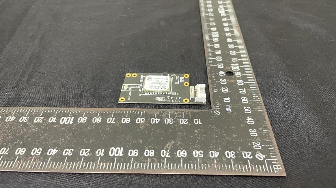
VTV-M7EDEKA
May 13, 2024UHD RFID Module
Equipment Class
DSS - Part 15 Spread Spectrum Transmitter
VTV-RFBHN
Jan 04, 2024Bluetooth module
Equipment Class
DTS - Digital Transmission System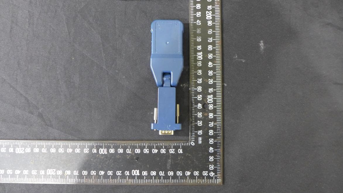
VTV-BA21N
Jan 29, 2023Bluetooth dongle
Equipment Class
DSS - Part 15 Spread Spectrum Transmitter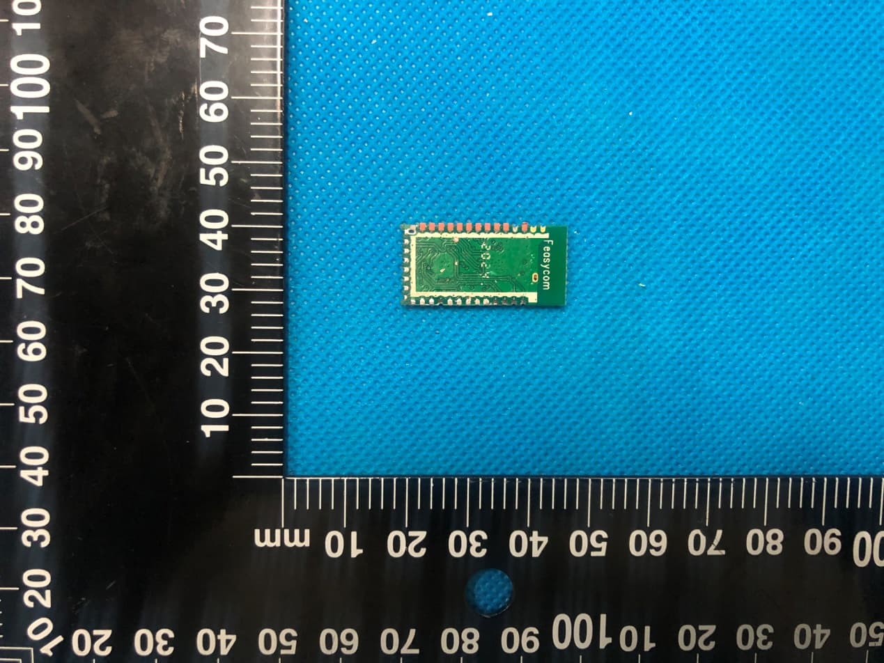
VTV-FSCBT826HC
Dec 24, 2020Bluetooth Module
Equipment Class
DTS - Digital Transmission System