VWZSR300Contactless Reader
SPECTRA Technologies Holdings Co. Ltd.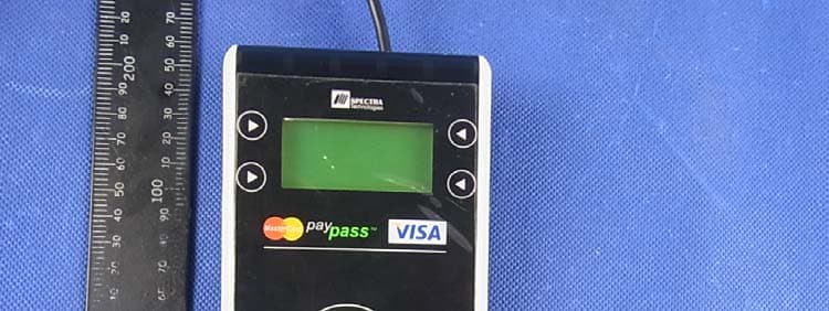
Click to zoom
Application Details
- Equipment Class
- DXX - Part 15 Low Power Communication Device Transmitter
- Date of Grant
- Jul 09, 2013
- Application Purpose
- Original Equipment
- Date of Application
- Jul 09, 2013
- Equipment Note
- Contactless Reader
- Frequency Range
- 13.56000000 - 13.56000000
- Country
- Hong Kong
Documents & Files
Document Text
Text extracted from the exhibit documents filed with the FCC. Open a document above to read the original.
Users Manual
SR300 CONTACTLESS CARD READER Installation Guide Version 1.0 SPECTRA Technologies ISO9001 : 2008 20002812 QM08 SPECTRA Technologies ISO14001 : 2004 20002812 UM SR300 1 Installation Guide SR300 Layout & Function Descriptions of SR300 1 1.1 Main Unit & Accessories Contactless Card Reader Desktop Stand (Optional) All-in-one Connection Cable Screws for Desktop Stand (Optional) Power Adaptor (Optional) - provides 8.5V DC supply 2 1.2 Features at a Glance SR300 LCD Display Capacitive Sensing Button Status Displaying LED Card Reading Area Cable Cover - Unless repairing engineer, please do not open the cover and unplug the cable connector Warning ! Reset Button SAM Card Door Screw Holes for Desktop Stand Installation Guide 3 1.3 Types of All-in-one Connection Cable 2 RS232 Communication Port Power Adaptor - provides 8.5V DC supply SR300 Installation Guide 4 1.4 Installation of SAM Card SR300 1 2 SAM Card - for version equipped with SAM card reader only Installation Guide 5 1.5 Assembling of Desktop Stand SR300 1 3 2 Install Desktop Stand by screwing the screws provided Adjust the required angle Tight fastening the lateral screws to fix the reader Installation Guide 6 How to Operate 2 2.1 Turn On Procedure Power is on whenever plugged. Transaction operation is ready. SR300 Installation Guide 7 Safety & Maintenance 3 3.1 Basic Safety Practice 3.2 Safety Warning While using SR300 and its accessories, please follow the safety instruction to avoid fire, electric shock and personal injury. Read this instruction in detail Disconnect the power and accessories before cleaning, use dry flannelette and soft brush for cleaning Do not place the unit near water Do not spray any liquid onto the unit Put the unit on stable platform to avoid damage by drop Keep the unit away from high temperature and poor ventilation area Ensure electricity supply is safe and stable To avoid electric shock, do not disassemble the unit by yourself. Send it to agency for repairing if necessary Do not use SR300 and its accessories during explosive gas leakage For the following cases, disconnect power, other accessories and send for repairing, ~ Damage on power cable or plug ~ Liquid get into pinpad ~ Pinpad gets wet in raining ~ Still abnormal function after following all the instruction mentioned ~ Pinpad broken ~ Pinpad obvious abnormal Using the provided cable or power adaptor to power the reader SR300 Installation Guide 8 3.3 Location for Installation 3.4 Maintenance Should be safe and convenient for operators and users Should be placed on stable working platform or mounted on wall securely for power and accessories connection Good ventilation and should have 20cm space around the pinpad DO NOT expose PR608 in following environment ~ Near electrical appliance with high frequency EM wave such as air conditioner, electric fan, motor, neon sign etc. ~ Liquid container such as water trough, sink, pond etc. ~ High temperature or humidity place ~ High containing of VOC, salty and dusty area ~ Sunlight or high thermal radiation area ~ Near demagnetizing system and magnetic security system SR300 has been designed to provide stable service for users with less maintenance. In order to ensure best performance, we suggested the followings. Avoid exposing in sunlight, high temperature, high humidity and dusty area Keep in dry, clean and tidy environment Do not keep in extreme hot and cold place Do not disassemble the AC/DC power adaptor Do not shake and thrash the pinpad heavily Cleaning of SR300 Use flannelette to remove dust on pinpad Use mild alcohol to remove stubborn stains If possible, use low pressure blower to blow out dust on keypad Use flannelette or lens cleaning paper to clean the display Send for repairing If it is necessary to send back SR300 for repairing, please contact agency, pack the pinpad properly (use original packing material if possible) to avoid damage during transportation SR300 Installation Guide FCC Caution: Any changes or modifications not expressly approved by the party responsible for compliance could void the user's authority to operate this equipment. This device complies with Part 15 of the FCC Rules. Operation is subject to the following two conditions: (1) This device may not cause harmful interference, and (2) this device must accept any interference received, including interference that may cause undesired operation. NOTE: This equipment has been tested and found to comply with the limits for a Class B digital device, pursuant to Part 15 of the FCC Rules. These limits are designed to provide reasonable protection against harmful interference in a residential installation. This equipment generates, uses and can radiate radio frequency energy and, if not installed and used in accordance with the instructions, may cause harmful interference to radio communications. However, there is no guarantee that interference will not occur in a particular installation. If this equipment does cause harmful interference to radio or television reception, which can be determined by turning the equipment off and on, the user is encouraged to try to correct the interference by one or more of the followingmeasures: -- Reorient or relocate the receiving antenna. -- Increase the separation between the equipment and receiver. -- Connect the equipment into an outlet on a circuit different from that to which the receiver is connected. -- Consult the dealer or an experienced radio/TV technician for help.
Cover Letter(s)
FCC Confidentiality Request To the FCC and FCC TCB handling this application for certification Pursuant to 47 CFR Section 0.459(a) & (b), we, (the applicant / grantee) Company name SPECTRA Technologies Holdings Co. Ltd Addresss Unit 1301-09, 19-20, Tower II, Grand Century Place, 193 Prince Edward Road West,Kowloon City Hong Kong Country CHINA request non-disclosure and confidential treatment for our certification under: Grantee Code Product Number FCC ID: VWZ SR300 of the following materials submitted within this certification application: (please cross what is applicable, or add other documents) x Operational Description x Block Diagrams x Schematics Diagrams Turn up produrce Bill of Materials Above materials contain secrets, proprietary and technical information, which would customarily be guarded from competitors under 47 CFR, section 0.457(d)(2). Disclosure or publication or any portion of this company confidential material to other parties could cause substantial competitive harm and provide unjustified benefits for competitors. We understand that pursuant to 47 CFR section 0.457(d)(1)(ii) disclosure of the applicant and all accompanying documentation will not be made before the date of the grant. Attestation: City and Country: Date: Name: (this must be a person) Function: Signature: (or official company stamp) Hong Kong 2013-5-17 Timothy Wong R & D Director
External Photos
APPENDIX-PHOTOGRAPHS OF EUT CONSTRUCTIONAL DETAILS Photo 1 Photo 2 Photo 3 Photo 4 Photo 5 Photo 6 Photo 7 Photo 8
Internal Photos
Photo 8 Photo 9 Photo 10 Photo 11 Photo 12 Photo 13 Antenna
Test Report
FCC RADIO TEST REPORT FCC ID: VWZSR300 Product: Contactless Reader Trade Name: SPECTRA Model Name: SR300 Serial Model: N/A Report No.: PTS2013050631F Prepared for SPECTRA Technologies Holdings Co. Ltd Unit 1301-09, 19-20, Tower II, Grand Century Place, 193 Prince Edward Road West, Kowloon, Hong Kong Prepared by DongGuan Precise Testing Service Co.,Ltd. F616A Room, 6th Floor, Meixin Business Center, Dongcheng Middle Road, Dongguan, Guangdong, China Tel: 86-769-23368601 Fax: 86-769-23368602 http:// www.pts-testing.com Page 2 of 30 Report No.: PTS2013050631F ` TEST RESULT CERTIFICATION Applicant’s name ................. : SPECTRA Technologies Holdings Co. Ltd Address ................................. : Unit 1301-09, 19-20, Tower II, Grand Century Place, 193 Prince Edward Road West, Kowloon, Hong Kong Manufacture's Name ............ : SPECTRA Technologies Holdings Co. Ltd Address ................................. : Unit 1301-09, 19-20, Tower II, Grand Century Place, 193 Prince Edward Road West, Kowloon, Hong Kong Product description Product name ........................... : Contactless Reader Model and/or type reference : SR300 Serial Model: N/A Standards ............................. : FCC Part15.225 Test procedure ..............................ANSI C63.4-2003 This device described above has been tested by PTS, and the test results show that the equipment under test (EUT) is in compliance with the FCC requirements. And it is applicable only to the tested sample identified in the report. This report shall not be reproduced except in full, without the written approval of PTS, this document may be altered or revised by PTS, personal only, and shall be noted in the revision of the document. Date of Test ............................................ : Date (s) of performance of tests ............. : 01.May2013 ~10.May. 2013 Date of Issue ........................................... : 10.May. 2013 Test Result ............................................... : Pass Testing Engineer : Assistant Technical Manager : Supervisor Authorized Signatory : Jacky Ou / Manager Page 3 of 30 Report No.: PTS2013050631F ` Table of Contents Page 1 . SUMMARY OF TEST RESULTS 4 1.1 TEST FACILITY 5 1.2 MEASUREMENT UNCERTAINTY 5 2 . GENERAL INFORMATION 6 2.1 GENERAL DESCRIPTION OF EUT 6 2.2 DESCRIPTION OF TEST MODES 7 2.3 BLOCK DIGRAM SHOWING THE CONFIGURATION OF SYSTEM TESTED 8 2.4 DESCRIPTION OF SUPPORT UNITS(CONDUCTED MODE) 9 2.5 EQUIPMENTS LIST FOR ALL TEST ITEMS 10 3 . ANTENNA REQUIREMENT 11 3.1 STANDARD REQUIREMENT 11 3.2 EUT ANTENNA 11 3.3 CONDUCTED EMISSION MEASUREMENT 12 3.3.1 POWER LINE CONDUCTED EMISSION LIMITS 12 3.3.2 TEST PROCEDURE 13 3.3.3 DEVIATION FROM TEST STANDARD 13 3.3.4 TEST SETUP 13 3.2.5 TEST RESULT 14 3.4 RADIATED EMISSION MEASUREMENT 16 3.4.1 RADIATED EMISSION LIMITS 16 3.4.2 TEST PROCEDURE 16 3.4.3 DEVIATION FROM TEST STANDARD 17 3.4.4 TEST SETUP 18 3.4.5 FIELD STRENGTH IN THE 13.553–13.567 MHZ BAND( A) 20 3.4.6 FIELD STRENGTH IN THE 13.410–13.553 MHZ AND 13.567–13.710(B) 21 3.4.7 FIELD STRENGTH IN THE 13.110–13.410 MHZ AND 13.710–14.010MHZ BANDS(C) 22 3.4.8 FIELD STRENGTH OF ANY EMISSIONS APPEARING OUTSIDE OF THE13.110–14.010 MHZ BAND(D) 23 3.4.9 FREQUENCY TOLERANCE OF THE CARRIER SIGNAL 26 3.4.10 . 20 BANDWIDTH TEST 27 3.4.11 DEVIATION FROM STANDARD 27 3.4.12 TEST SETUP 27 3.4.13 TEST RESULTS 28 4 . EUT TEST PHOTO 29 APPENDIX-PHOTOGRAPHS OF EUT CONSTRUCTIONAL DETAILS Page 4 of 30 Report No.: PTS2013050631F ` 1. SUMMARY OF TEST RESULTS Test procedures according to the technical standards: FCC Part15, Subpart C (15.225) Standard Section Test Item Judgment Remark 15.207 Conducted Emission Pass 15.215(c) 20dB Bandwidth Pass 15.203 Antenna Requirement Pass 15.225(a) Field strength in the 13.553–13.567 MHz band Pass 15.225(b) Field strength in the 13.410–13.553 MHz and 13.567–13.710 MHz band Pass 15.225(c) Field strength in the 13.110–13.410 MHz and 13.710–14.010 MHz band Pass 15.225(d) Field strength of any emissions appearing outside of the 13.110–14.010MHz band Pass 15.225(e) Frequency tolerance of the carrier signalPass 15.225(f) Radio frequency powered tags N/A Note(1) NOTE: (1) ” N/A” denotes test is not applicable in this Test Report. Page 5 of 30 Report No.: PTS2013050631F ` 1.1 TEST FACILITY NTEK Testing Technology Co., Ltd Add. : 1/F, Building E, Fenda Science Park, Sanwei Community, Xixiang Street, Bao’an District, Shenzhen P.R. China. FCC FRN Registration No.:238937; IC Registration No.:9270A-1 1.2 MEASUREMENT UNCERTAINTY The reported uncertainty of measurement y ± U,where expended uncertainty U is based on a standard uncertainty multiplied by a coverage factor of k=2,providing a level of confidence of approximately 95 %。 No. Item Uncertainty 1 Conducted Emission Test ±1.38dB 2 RF power,conducted ±0.16dB 3 Spurious emissions,conducted ±0.21dB 4 All emissions,radiated(<1G) ±4.68dB 5 All emissions,radiated(>1G) ±4.89dB 6 Temperature ±0.5°C 7 Humidity ±2% Page 6 of 30 Report No.: PTS2013050631F ` 2. GENERAL INFORMATION 2.1 GENERAL DESCRIPTION OF EUT Equipment Contactless Reader Trade Name N/A Model Name SR300 Serial Model N/A Model Difference N/A Product Description The EUT is a Contactless Reade r Product Type Remote Control Operation Frequency: 13.56MHz Modulation Type: AM Number Of Channel 1CH. Antenna Designation: Printed antenna Antenna Gain(Peak) 1.2 dBi Output Power: 61.9dBuV/m (PK Max.) Based on the application, features, or specification exhibited in User's Manual, the EUT is considered as an ITE/Computing Device. More details of EUT technical specification, please refer to the User's Manual. Channel List N/A Adapter Model: M01203 INPUT: AC100~240V,50/60Hz,0.25A OUTPUT:5.0V/1.0A Battery N/A Note: 1. For a more detailed features description, please refer to the manufacturer’s specifications or the User's Manual. 2. Table for Filed Antenna Ant . Brand Model Name Antenna Type Connector Gain (dBi) NOTE 1 N/A N/A Printed antennaNA 1.2 Antenna Page 7 of 30 Report No.: PTS2013050631F ` 2…
Text truncated - open the document above for the full version.
Test Setup Photos
Page 29 of 30 Report No.: PTS2013050631F ` 4. EUT TEST PHOTO Radiated Measurement Photos Page 30 of 30 Report No.: PTS2013050631F ` Conducted Measurement Photos
Contact Information
Applicant
Terry TAM(Manager, Product Development)
Test Firm
NTEK Testing Technology Co., Ltd.Wetow Huang
Technical Specifications
| # | Rule Parts | Frequency Range | Power Output | Tolerance |
|---|---|---|---|---|
| 1 | 15C | 13.56 MHz - 13.56 MHz | - | 0.0100000000 % |
Other Applications from SPECTRA Technologies Holdings Co. Ltd.
VWZS1
Sep 04, 2024Android POS
Equipment Class
PCB - PCS Licensed Transmitter
VWZTA10Q
Jan 14, 2021Android POS
Equipment Class
DSS - Part 15 Spread Spectrum Transmitter
VWZTA10V
Nov 03, 2020Android POS
Equipment Class
NII - Unlicensed National Information Infrastructure TX
VWZT1000I
May 13, 2015EFTPOS
Equipment Class
DXX - Part 15 Low Power Communication Device Transmitter
VWZT1000
Jul 17, 2012EFTPOS
Equipment Class
PCT - PCS Licensed Transmitter worn on body