VZ9130004Enterprise Access Point
4IPNET, INC.
Click to zoom
Application Details
- Equipment Class
- DTS - Digital Transmission System
- Date of Grant
- Jan 06, 2015
- Application Purpose
- Original Equipment
- Date of Application
- Jan 05, 2015
- Equipment Note
- Enterprise Access Point
- Frequency Range
- 2412.00000000 - 2462.00000000
- Company
- 4IPNET, INC.
- Country
- Taiwan
Documents & Files
Document Text
Text extracted from the exhibit documents filed with the FCC. Open a document above to read the original.
Users Manual
EAP701 V1.00 Enterprise Access Point Quick Installation Guide EAP701 Enterprise Access Point ENGLISH Copyright © 4IPNET, INC. All rights reserved. i Copyright Notice This document is protected by USA copyright laws and other laws. Besides, the document is the property of 4IPNET, INC. You may not copy, reproduce, distribute, publish, display, perform, or modify any part of this publication in any form or by any means without prior written permission from 4IPNET, INC. You may not alter or remove any copyright or other notice from copies of the content. All other brand and product names are claimed or registered marks of their respective companies or organizations. All rights reserved. To download up-to-date version, please visit www.4ipnet.com. Quick Installation Guide EAP701 Enterprise Access Point ENGLISH Copyright © 4IPNET, INC. All rights reserved. ii FCC CAUTION This equipment has been tested and proven to comply with the limits for a class B digital device, pursuant to part 15 of the FCC Rules. These limits are designed to provide reasonable protection against harmful interference in a residential installation. This equipment generates uses and can radiate radio frequency energy and, if not installed and used in accordance with the instructions, may cause harmful interference to radio communications. However, there is no guarantee that interference will not occur in a particular installation. If this equipment does cause harmful interference to radio or television reception, which can be determined by turning the equipment off and on, the user is encouraged to try to correct the interference by one or more of the following measures: ---Reorient or relocate the receiving antenna. ---Increase the separation between the equipment and receiver. ---Connect the equipment into an outlet on a circuit different from that to which the receiver is connected. ---Consult the dealer or an experienced radio/TV technician for help. The device contains a low power transmitter which will send out Radio Frequency (RF) signal when transmitting. This equipment complies with FCC RF radiation exposure limits set forth for an uncontrolled environment. This equipment should be installed and operated with a minimum distance of 20 centimeters between the radiator and your body. This device complies with Part 15 of the FCC Rules. Operation is subject to the following two conditions: (1) This device may not cause harmful interference, and (2) this device must accept any interference received, including interference that may cause undesired operation. Any changes or modifications not expressly approved by the party responsible for compliance could void the user's authority to operate this equipment. This transmitter must not be co-located or operating in conjunction with any other antenna or transmitter. Quick Installation Guide EAP701 Enterprise Access Point ENGLISH Copyright © 4IPNET, INC. All rights reserved. iii CE CAUTION Declaration of Conformity with Regard to the 1999/5/EC (R&TTE Directive) for European Community, Switzerland, Norway, Iceland, and Liechtenstein Model: EAP701 For 2.4 GHz radios, the device has been tested and passed the requirements of the following standards, and hence fulfills the EMC and safety requirements of R&TTE Directive within the CE marking requirement. • Radio: EN 300.328 : • EMC: EN 301.489-1, EN 301.489-17, • EMC: EN 55022 Class B, EN 55024 : + A1 + A2 including the followings: EN 61000-3-2, EN 61000-3-3. EN 61000-4-2, EN 61000-4-3, EN 61000-4-4, EN 61000-4-5, EN 61000-4-6, EN 61000-4-11 • Safety: EN 60950-1 + A11, Caution: This declaration is only valid for configurations (combinations of software, firmware, and hardware) provided and supported by 4ipnet Inc. The use of software or firmware not provided and supported by 4ipnet Inc. may result in the equipment no longer being compliant with the regulatory requirements. European standards dictate maximum radiated transmit power of 100mW EIRP and frequency range 2.400-2.4835 GHz. This equipment is intended to be used in all EU and EFTA countries. Outdoor use may be restricted to certain frequencies and/or may require a license for operation. Contact your local regulatory authority for compliance. Taiwan NCC Statement 根據NCC低功率電波輻射性電機管理辦法 規定: 第十二條 經型式認證合格之低功率射頻電機,非經許可,公司、商號或使用者均不得擅自變更頻率、加大功率或 變更原設計之特性及功能。 第十四條 低功率射頻電機之使用不得影響飛航安全及干擾合法通信;經發現有干擾現象時應立即停用,並改善至 無干擾時方得繼續使用。 前項合法通信,指依電信法規定作業之無線電通信。 低功率射頻電機須忍受合法通信或工業、科學及醫療用電波輻射性電機設備之擾。 Quick Installation Guide EAP701 Enterprise Access Point ENGLISH Copyright © 4IPNET, INC. All rights reserved. 1 Preface Package Contents The 4ipnet EAP701 Wall Jack Access Point is an in/on-the-wall as well as a ceiling-mounted Wi-Fi IEEE 802.11b/g/n 2.4GHz 2 X 2 MIMO access point, designed to blend into a working or a living environment practically and elegantly with its simplistic yet sleek design. The compact EAP701 in a small form factor lays snug in a standard wall outlet box. Its side panel features LED status indicators and two RJ45 ports. It has the interfaces to serve both wireless and wired LAN access. When coupled with the 4ipnet WHG series Controller, the EAP701 supports Tunnel-based AP Management, and comes with all standards demanded by enterprise applications, including business-grade security (802.1X, WPA and WPA2), and multiple ESSIDs with VLAN tags to separate the traffics of different departments. A centralized WLAN management allows enterprises and organizations to support a wide array of value added applications, such as load balancing, bandwidth control, and access control. The patent-pending 4ipWES (Press-n-Connect) technology bridges multiple EAP701s at the touch of a button, which enables a quick and automatic WDS Easy Setup by pressing the WES button on EAP701. Extending wireless network coverage is a breeze, be it across conference rooms or along hallways. EAP701’s high performance, security and optimal invisibility make it a perfect choice of wireless connectivity for your busin…
Text truncated - open the document above for the full version.
External Photos
Page 1 CONSTRUCTION PHOTOS OF EUT Page 2
Internal Photos
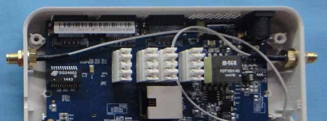
Page 3 Page 4 Page 5 Page 6 Page 7 Page 8
RF Exposure Info
Report No.: SA131105E06 1 of 6 Report Format Version 5.0.0 RF EXPOSURE REPORT REPORT NO.: SA131105E06 MODEL NO.: EAP701 FCC ID: VZ9130004 RECEIVED: Nov. 5, 2013 TESTED: Nov. 19 ~ 25, 2013 ISSUED: Dec. 16, 2013 APPLICANT: 4IPNET, INC. ADDRESS: 3F-3, No. 369, Fusing N. Rd., Taipei 105, Taiwan,R.O.C. ISSUED BY: Bureau Veritas Consumer Products Services (H.K.) Ltd., Taoyuan Branch LAB ADDRESS: No. 47, 14th Ling, Chia Pau Vil., Lin Kou Dist., New Taipei City, Taiwan, R.O.C. This report is for your exclusive use. Any copying or replication of this report to or for any other person or entity, or use of our name or trademark, is permitted only with our prior written permission. This report sets forth our findings solely with respect to the test samples identified herein. The results set forth in this report are not indicative or representative of the quality or characteristics of the lot from which a test sample was taken or any similar or identical product unless specifically and expressly noted. Our report includes all of the tests requested by you and the results thereof based upon the information that you provided to us. You have 60 days from date of issuance of this report to notify us of any material error or omission caused by our negligence, provided, however, that such notice shall be in writing and shall specifically address the issue you wish to raise. A failure to raise such issue within the prescribed time shall constitute your unqualified acceptance of the completeness of this report, the tests conducted and the correctness of the report contents. Unless specific mention, the uncertainty of measurement has been explicitly taken into account to declare the compliance or non-compliance to the specification. Report No.: SA131105E06 2 of 6 Report Format Version 5.0.0 TABLE OF CONTENTS RELEASE CONTROL RECORD ................................................................................ 3 1. CERTIFICATION ........................................................................................... 4 2. RF EXPOSURE LIMIT .................................................................................. 5 3. MPE CALCULATION FORMULA .................................................................. 5 4. CLASSIFICATION ......................................................................................... 5 5. CALCULATION RESULT OF MAXIMUM CONDUCTED POWER ............... 6 Report No.: SA131105E06 3 of 6 Report Format Version 5.0.0 RELEASE CONTROL RECORD ISSUE NO. REASON FOR CHANGE DATE ISSUED SA131105E06 Original release Dec. 16, 2013 Report No.: SA131105E06 4 of 6 Report Format Version 5.0.0 1. CERTIFICATION PRODUCT: Enterprise Access Point MODEL NO.: EAP701 BRAND: 4ipnet APPLICANT: 4IPNET, INC. TESTED: Nov. 19 ~ 25, 2013 TEST SAMPLE: ENGINEERING SAMPLE STANDARDS: FCC Part 2 (Section 2.1091) FCC OET Bulletin 65, Supplement C (01-01) IEEE C95.1 The above equipment has been tested by Bureau Veritas Consumer Products Services (H.K.) Ltd., Taoyuan Branch, and found compliance with the requirement of the above standards. The test record, data evaluation & Equipment Under Test (EUT) configurations represented herein are true and accurate accounts of the measurements of the sample’s EMC characteristics under the conditions specified in this report. PREPARED BY : , DATE:Dec. 16, 2013 ( Annie Chang / Supervisor ) APPROVED BY : , DATE:Dec. 16, 2013 ( Rex Lai / Assistant Manager ) Report No.: SA131105E06 5 of 6 Report Format Version 5.0.0 2. RF EXPOSURE LIMIT LIMITS FOR MAXIMUM PERMISSIBLE EXPOSURE (MPE) FREQUENCY RANGE (MHz) ELECTRIC FIELD STRENGTH (V/m) MAGNETIC FIELD STRENGTH (A/m) POWER DENSITY (mW/cm 2 ) AVERAGE TIME (minutes) LIMITS FOR GENERAL POPULATION / UNCONTROLLED EXPOSURE 300-1500 ... ... F/1500 30 1500-100,000 ... ... 1.0 30 F = Frequency in MHz 3. MPE CALCULATION FORMULA Pd = (Pout*G) / (4*pi*r2) where Pd = power density in mW/cm2 Pout = output power to antenna in mW G = gain of antenna in linear scale Pi = 3.1416 R = distance between observation point and center of the radiator in cm 4. CLASSIFICATION The antenna of this product, under normal use condition, is at least 20cm away from the body of the user. So, this device is classified as Mobile Device. Report No.: SA131105E06 6 of 6 Report Format Version 5.0.0 5. CALCULATION RESULT OF MAXIMUM CONDUCTED POWER FREQUENCY BAND (MHz) MAX POWER (dBm) ANTENNA GAIN (dBi) DISTANCE (cm) POWER DENSITY (mW/cm 2 ) LIMIT (mW/cm 2 ) 2.412 ~ 2.462 25.62 2 20 0.115 1.00 --- END ---
Test Report
Report No.: RF131105E06 1 of 58 Report Format Version 5.2.0 FCC TEST REPORT (WLAN 15.247) REPORT NO.: RF131105E06 MODEL NO.: EAP701 FCC ID: VZ9130004 RECEIVED: Nov. 5, 2013 TESTED: Nov. 19 ~ 25, 2013 ISSUED: Dec. 16, 2013 APPLICANT: 4IPNET, INC. ADDRESS: 3F-3, No. 369, Fusing N. Rd., Taipei 105, Taiwan,R.O.C. ISSUED BY: Bureau Veritas Consumer Products Services (H.K.) Ltd., Taoyuan Branch LAB ADDRESS: No. 47, 14th Ling, Chia Pau Vil., Lin Kou Dist., New Taipei City, Taiwan This report is for your exclusive use. Any copying or replication of this report to or for any other person or entity, or use of our name or trademark, is permitted only with our prior written permission. This report sets forth our findings solely with respect to the test samples identified herein. The results set forth in this report are not indicative or representative of the quality or characteristics of the lot from which a test sample was taken or any similar or identical product unless specifically and expressly noted. Our report includes all of the tests requested by you and the results thereof based upon the information that you provided to us. You have 60 days from date of issuance of this report to notify us of any material error or omission caused by our negligence, provided, however, that such notice shall be in writing and shall specifically address the issue you wish to raise. A failure to raise such issue within the prescribed time shall constitute your unqualified acceptance of the completeness of this report, the tests conducted and the correctness of the report contents. Unless specific mention, the uncertainty of measurement has been explicitly taken into account to declare the com pliance or non-compliance to the specification. This report should not be used by the client to claim product certification, approval, or endorsement by TAF or any government agencies. Report No.: RF131105E06 2 of 58 Report Format Version 5.2.0 TABLE OF CONTENTS RELEASE CONTROL RECORD ................................................................................ 4 1. CERTIFICATION .............................................................................................. 5 2. SUMMARY OF TEST RESULTS ..................................................................... 6 2.1 MEASUREMENT UNCERTAINTY ................................................................... 6 3. GENERAL INFORMATION .............................................................................. 7 3.1 GENERAL DESCRIPTION OF EUT ................................................................ 7 3.2 DESCRIPTION OF TEST MODES .................................................................. 8 3.2.1 TEST MODE APPLICABILITY AND TESTED CHANNEL DETAIL ................... 9 3.3 DUTY CYCLE OF TEST SIGNAL .................................................................. 11 3.4 DESCRIPTION OF SUPPORT UNITS .......................................................... 12 3.4.1 CONFIGURATION OF SYSTEM UNDER TEST ............................................ 12 3.5 GENERAL DESCRIPTION OF APPLIED STANDARDS ................................ 14 4. TEST TYPES AND RESULTS ....................................................................... 15 4.1 RADIATED EMISSION AND BANDEDGE MEASUREMENT ........................ 15 4.1.1 LIMITS OF RADIATED EMISSION AND BANDEDGE MEASUREMENT ...... 15 4.1.2 TEST INSTRUMENTS ................................................................................... 16 4.1.3 TEST PROCEDURES ................................................................................... 17 4.1.4 DEVIATION FROM TEST STANDARD .......................................................... 17 4.1.5 TEST SETUP ................................................................................................. 18 4.1.6 EUT OPERATING CONDITIONS .................................................................. 19 4.1.7 TEST RESULTS ............................................................................................ 20 4.2 CONDUCTED EMISSION MEASUREMENT ................................................. 34 4.2.1 LIMITS OF CONDUCTED EMISSION MEASUREMENT .............................. 34 4.2.2 TEST INSTRUMENTS ................................................................................... 34 4.2.3 TEST PROCEDURES ................................................................................... 35 4.2.4 DEVIATION FROM TEST STANDARD .......................................................... 35 4.2.5 TEST SETUP ................................................................................................. 35 4.2.6 EUT OPERATING CONDITIONS .................................................................. 35 4.2.7 TEST RESULTS ............................................................................................ 36 4.3 6dB BANDWIDTH MEASUREMENT ............................................................. 38 4.3.1 LIMITS OF 6dB BANDWIDTH MEASUREMENT .......................................... 38 4.3.2 TEST SETUP ................................................................................................. 38 4.3.3 TEST INSTRUMENTS ................................................................................... 38 4.3.4 TEST PROCEDURE ...................................................................................... 38 4.3.5 DEVIATION FROM TEST STANDARD .......................................................... 38 4.3.6 EUT OPERATING CONDITIONS .................................................................. 38 Report No.: RF131105E06 3 of 58 Report Format Version 5.2.0 4.3.7 TEST RESULTS ............................................................................................ 39 4.4 CONDUCTED OUTPUT POWER .................................................................. 41 4.4.1 LIMITS OF CONDUCTED OUTPUT POWER MEASUREMENT ................... 41 4.4.2 TEST SETUP .................................................................................…
Text truncated - open the document above for the full version.
Test Setup Photos
1 of 3 PHOTOGRAPHS OF THE TEST CONFIGURATION CONDUCTED EMISSION TEST (Mode A) 2 of 3 RADIATED EMISSION TEST (Mode A) 3 of 3 RADIATED EMISSION TEST (Mode B)
Contact Information
Applicant
Teng Tai Hsu(President)
Test Firm
Bureau Veritas CPS (H.K.) Ltd., Taoyuan BranchRichard Chen
Technical Specifications
| # | Rule Parts | Frequency Range | Power Output |
|---|---|---|---|
| 1 | 15C | 2.41 GHz - 2.46 GHz | 364.00 mW |
Other Applications from 4IPNET, INC.
VZ9150001
Jun 03, 2015Enterprise Access Point/ Wireless Hotspot Gateway/ Cluster Access Point
Equipment Class
NII - Unlicensed National Information Infrastructure TX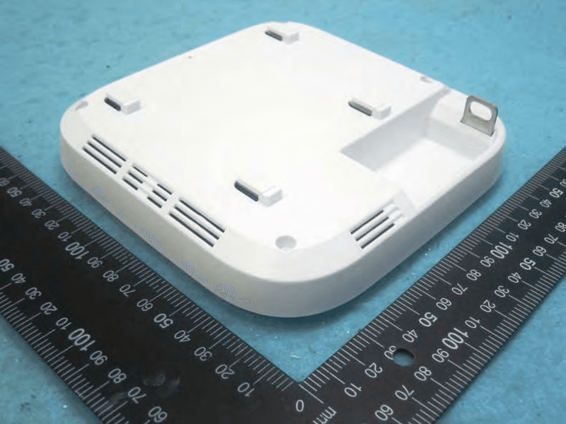
VZ9140003
Oct 15, 2014Enterprise Access Point
Equipment Class
NII - Unlicensed National Information Infrastructure TX
VZ9130002
Aug 20, 2014Enterprise Access Point
Equipment Class
DTS - Digital Transmission System
VZ9140001
May 26, 2014ENTERPRISE ACCESS POINT
Equipment Class
DTS - Digital Transmission System
VZ9120002
Feb 12, 2014802.11a/b/g/n Wireless Module
Equipment Class
NII - Unlicensed National Information Infrastructure TX