VZKST4Guard RFID WiFi staff/employee tag
Guard RFID Solutions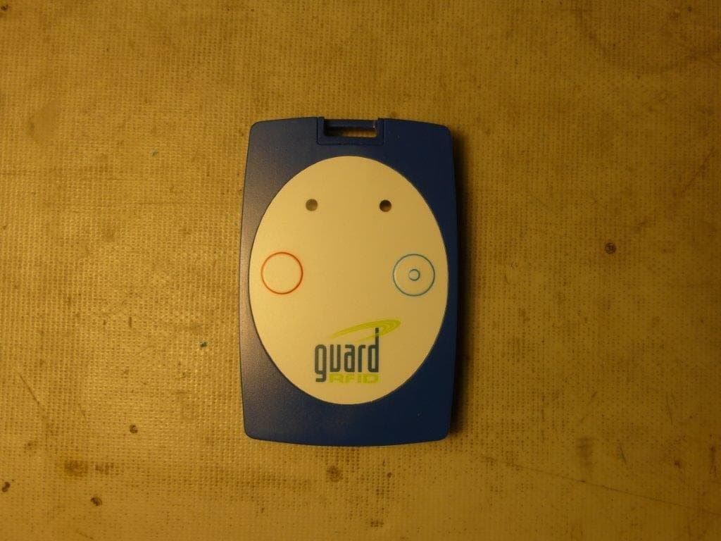
Click to zoom
Application Details
- Equipment Class
- DTS - Digital Transmission System
- Date of Grant
- Jan 03, 2023
- Application Purpose
- Original Equipment
- Date of Application
- Jan 03, 2023
- Equipment Note
- Guard RFID WiFi staff/employee tag
- Frequency Range
- 2412.00000000 - 2462.00000000
- Company
- Guard RFID Solutions
- Country
- Canada
Documents & Files
Document Text
Text extracted from the exhibit documents filed with the FCC. Open a document above to read the original.
Users Manual
Guard RFID Solutions Inc. [email protected] • 866.785.7343 Specifications Subject to Change Without Notice. ©2020-2022 Guard RFID Solutions, Inc. All rights reserved. GuardRFID and AllGuard are registered trademarks of Guard RFID Solutions Inc. TM 02-00157-132 Wi-Fi Staff Tag ST-4-WIFI DESCRIPTION: The ST-4-WIFI is a tag that is designed for locating, communicating and providing security to personnel. These tags leverage existing Wi-Fi networks to work with GuardRFID ® exciters and AllGuard ® software to determine the tag location in real-time. Each Wi-Fi Staff Tag has two configurable buttons and a built-in pull duress function that allows users to send alerts to the AllGuard system to help manage potentially hazardous situations. The tag can also receive alerts or acknowledgements f rom the AllGuard system and shows the notification through the indicator lights and/or sound on the tag. The Wi-Fi Staff Tag is powered by an internal, wireless rechargeable battery. To help extend battery life, the tag includes an internal motion detector to automatically adjust the beacon rate and manage power consumption. When you receive the tags, a tag activator may be needed to prompt each new tag to request configuration settings f rom the AllGuard server. Subsequent configurations and firmware updates occur over-the-air using the Wi-Fi network. Product ST-4-WIFI Part Number61-10402 Software CompatibilityAllGuard Server 6.5.0+ User Interfaces 2 x buttons (configurable), 2 x visual indicators, audio transducer, pull duress alarm trigger SensorsMotion Detection, LF Receiver, Accelerometer Operating Modes SAP: Standalone Access Point mode works with most Wi-Fi access points. *contact GuardRFID for a list of compatible access points CCX: Cisco Compatible Extension mode requires Cisco access points and supplementary equipment. Wi-Fi SecurityWPA2-PSK Range30 m (100 ft) max. in a typical indoor healthcare environment Transmit Frequency2.4GHz (802.11 b compliant) Receive Frequency2.4GHz (802.11 b compliant), 125kHz Battery Life Wireless recharging (6 hours for full charge) (Battery life is dependent on use case and configuration. The estimates below are based on typical usage for a Staff Duress solution.) •SAP mode — typical 1 month before recharge •CCX mode — typical 3 months before recharge Beacon Interval Active / inside exciter field: 12 seconds, configurable Static: configurable. Dimensions80 mm x 53 x 12 (3.1 in x 2.1 x 0.5) Weight46 g (1.6 oz) WaterproofSplashproof (designed to IP68) Operating Temperature-20°C to 50°C (-4° F to 122°F) Humidity0 – 100% RH RegulatoryFCC, IC Warranty12 months FEATURES: •Leverages Wi-Fi networks to provide real-time location information. •2 x configurable buttons •Built-in pull-duress alarm •Audio/visual indicators for motion and battery charging status •Includes wireless rechargeable battery •Over-the-air upgrades •Uses WPA2 to encrypt communication with system SPECIFICATIONS: Guard RFID Solutions Inc. [email protected] • 866.785.7343 Specifications Subject to Change Without Notice. ©2020-2022 Guard RFID Solutions, Inc. All rights reserved. GuardRFID and AllGuard are registered trademarks of Guard RFID Solutions Inc. TM 02-00157-132 Accessories ST-4-WIFI WI-FI TAG CHARGER: Part Number: 61-14024 •For ST-4-WIFI tags •Can charge up to 10 tags at a time •Charge all tags within 6 hours •190.5 mm x 295.91 mm x 25 mm (7.50” x 11.65” x 0.98”) TAG ACTIVATOR: Part Number: 61-20028 •For configuring the Wi-Fi tags •Required for activating new Wi-Fi tags in a system REQUIRED WI-FI RTLS LICENSES: Part Number: 62-50033 •1-year Wi-Fi integration license for AllGuard software (annual) Part Number: 62-40054 •1-year Wi-Fi tag support license per tag (annual) This device complies with part 15 of the FCC Rules and with Industry Canada license‐exempt RSS standard(s). Operation is subject to the following two conditions: (1) This device may not cause harmful interference, and (2) this device must accept any interference received, including interference that may cause undesired operation. Cet appareil est conforme à la spécification RSS-247 d’Industry Canada. Son fonctionnement est soumis aux deux conditions suivantes: (1) cet appareil ne peut engendrer aucune interférence et (2) il doit accepter toute interférence qu’il reçoit, y compris celles qui peuvent altérer son fonctionnement NOTE: THE MANUFACTURER IS NOT RESPONSIBLE FOR ANY RADIO OR TV INTERFERENCE CAUSED BY UNAUTHORIZED MODIFICATIONS TO THIS EQUIPMENT SUCH MODIFICATIONS COULD VOID THE USER’S AUTHORITY TO OPERATE THE EQUIPMENT.
Cover Letter(s)
#140 – 760 Cliveden Place Delta, BC Canada V3M 6C7 T: 604.998.4018 F: 604.524.4018 www.guardrfid.com Oct 27, 2022 Guard RFID Solutions Inc. #140-766 Cliveden Place Delta, BC V3M 6C7 SUBJECT: FCCID: VZKST4 To Whom It May Concern: We, the undersigned, hereby authorize Zahra Vali at LabTest Certification Inc, Delta, BC, Canada on our behalf, to apply to the Federal Communications Commission on our equipment. Any and all acts carried out by Zahra Vali on our behalf shall have the same effect as acts of our own. This is to advise that we are in full compliance with the Anti-Drug Abuse Act. We, the applicant, are not subject to a denial of federal benefits pursuant to Section 5301 of the Anti-Drug Act of 1988, 21 USC853a, and no party to the application is subject to a denial of federal benefits pursuant to that section. Regards, Dalibor Pokrajac CTO and VP of Engineering Guard RFID Solutions 604-282-7584
Cover Letter(s)
#140 – 760 Cliveden Place Delta, BC Canada V3M 6C7 T: 604.998.4018 F: 604.524.4018 www.guardrfid.com Oct 21, 2022 Federal Communications Commission Authorization and Evaluation Division Confidentiality Request regarding application for certification of FCC ID: VZKST4 Pursuant to Sections 0.457 and 0.459 of the Commission’s Rules, we hereby request confidential treatment of information accompanying this application as outlined below: Exhibit Type File Name Schematic Theory of Operation Block Diagram 11-00040-200 (ST-4 SCH).pdf 03-00073-100 (ST-4 Theory Of Operation).pdf 03-00074-100 (ST-4 Block Diagram).pdf The above materials contain trade secrets and proprietary information not customarily released to the public. The public disclosure of these materials may be harmful to the applicant and provide unjustified benefits to its competitors. The applicant understands that pursuant to Section 0.457 of the Rules, disclosure of this application and all accompanying documentation will not be made before the date of the Grant for this application. Sincerely, Dalibor Pokrajac CTO and VP of Engineering Guard RFID Solutions Inc. 604-282-7584
ID Label/Location Info
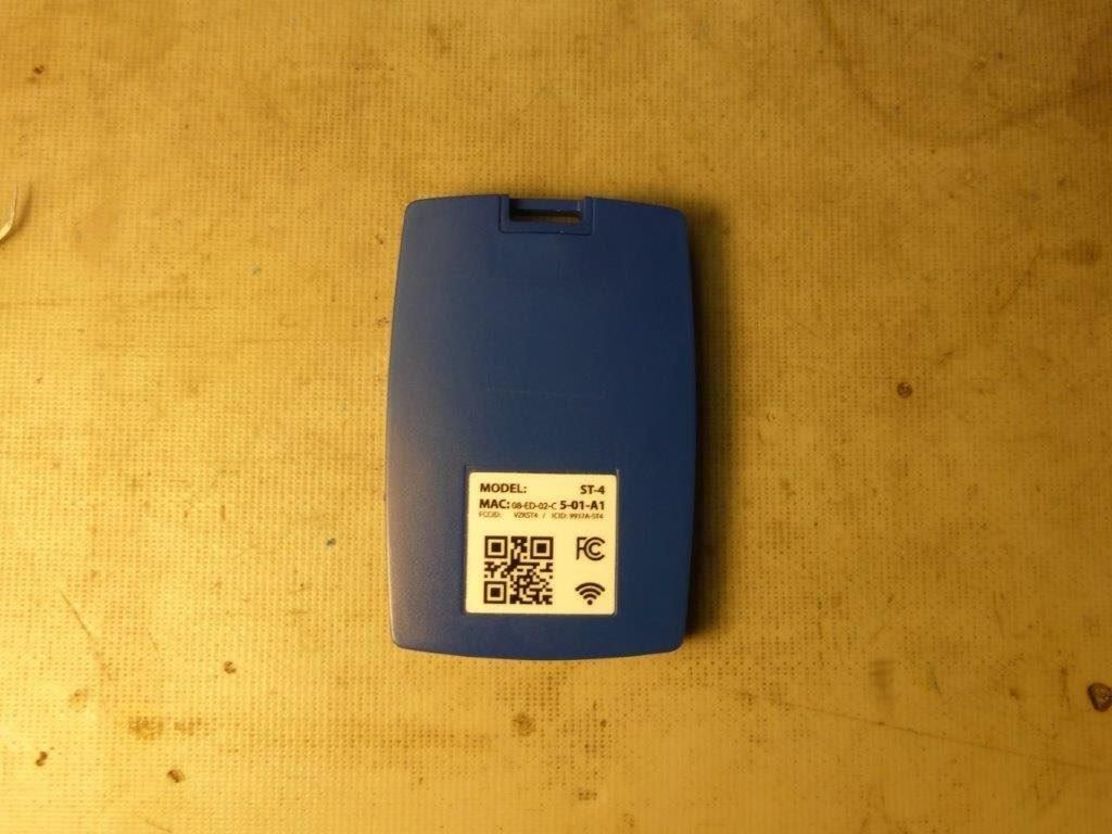
LABEL LAYOUT (top view) 25.00 24.00 R0.5 (4X) MODEL: ST-4 MAC : 08-ED-02-C5-00-20 FCC ID: VZKST4 / IC ID: 9937A-ST4 MODEL: ST-4 MAC : 08-ED-02-C5-00-20 FCC ID: VZKST4 / IC ID: 9937A-ST4 MODEL: ST-4 MAC : 08-ED-02-C5-00-30 FCC ID: VZKST4 / IC ID: 9937A-ST4 MODEL: ST-4 MAC : 08-ED-02-C5-00-21 FCC ID: VZKST4 / IC ID: 9937A-ST4 MODEL: ST-4 MAC : 08-ED-02-C5-00-22 FCC ID: VZKST4 / IC ID: 9937A-ST4 . . . . .
Internal Photos
2.4GHz antenna
RF Exposure Info
RF Exposure Evaluation REPORT For Guard RFID Solutions Inc. #140 – 766 Cliveden Place Delta, British Columbia V3M 6C7, Canada Date: 04 October 2022 Project No.: 21145 FCC ID: VZKST4 IC ID.: 9937A-ST4 Equipment: WiFi Staff Tag Model No.: ST-4 Labtest Certification ONE STOP GLOBAL CERTIFICATION SOLUTIONS ISO 17020 Accredited ISO 17025 accredited ISO 17065 Accredited Unit 205 – 8291 92 ST., Delta, BC V4G 0A4, Canada Phone: 604-247-0444 Fax: 604-247-0442 www.labtestcert.com Page 2 of 2 This document shall not be reproduced or utilized in any form or by any means, electronic or mechanical, including photocopying and microfilm, without permission in writing from LabTest Certification Inc. KDB 447498 D01 General RF Exposure Guidance v06, section 4.3.1 (a) For 100 MHz to 6 GHz and test separation distances ≤ 50 mm, the 1-g and 10-g SAR test exclusion thresholds are determined by the following: [(max. power of channel, including tune-up tolerance, mW) / (min. test separation distance, mm)] · [√f(GHz)] ≤ 3.0 for 1-g SAR, and ≤ 7.5 for 10-g extremity SAR, where • f(GHz) is the RF channel transmit frequency in GHz • Power and distance are rounded to the nearest mW and mm before calculation • The result is rounded to one decimal place for comparison Calculation: Information of the EUT is added in the below table. Frequency (GHz) Conducted Output Peak Power (dBm) Conducted Output Peak Power (mW) Min Test Separation Distance (mm) 2.412-2.462 5.969 3.95 5 [(max. power of channel, including tune-up tolerance, mW) / (min. test separation distance, mm)] · [√f(GHz)] = 1.24 ≤ 3 Conclusions The SAR test exclusion thresholds are met.
Test Report
ONE STOP GLOBAL CERTIFICATION SOLUTIONS ISO 17025 ACCREDITED ISO 17020 ACCREDITED ISO 17065 ACCREDITED 205 – 8291 92 Street, Delta, BC V4G 0A4, Canada Phone: 604-247-0444 Fax: 604-247-0442 www.labtestcert.com REPORT For Guard RFID Solutions Inc #140 – 766 Cliveden Place Delta, British Columbia V3M 6C7, Canada Date of Issue: 4 October 2022 Report No.: 20.01.21145 - 2_Rev0_GaurdRFID Project No.: 21145 Equipment: WiFi Staff Tag Model No.: ST-4 Prepared by: LabTest Certification Inc. Client: Guard RFID Solutions Inc Page 2 of 42 This document shall not be reproduced or utilized in any form or by any means, electronic or mechanical, including photocopying and microfilm, without permission in writing from LabTest Certification Inc. DCN: 1036, Rev 3 RA TABLE OF CONTENTS TEST REPORT_ FCC Part 15C/ ISED RSS-247 ......................................................................................... 3 Revision History ............................................................................................................................................. 4 Result Summary ............................................................................................................................................ 5 Description of Equipment Under Test and Variant Models ........................................................................... 6 Radio Device Under Test Description ........................................................................................................... 6 EUT Internal Operating Frequencies............................................................................................................. 7 Client Equipment Used During Test .............................................................................................................. 7 Software and Firmware ................................................................................................................................. 7 Input/Output Ports ......................................................................................................................................... 8 Power Interface ............................................................................................................................................. 8 EUT Operation Modes ................................................................................................................................... 8 EUT Configuration Modes ............................................................................................................................. 8 Measurement Uncertainty ............................................................................................................................. 9 1- 6-dB Occupied Bandwidth .............................................................................................................. 10 Test Setup ................................................................................................................................................ 10 Test Results ............................................................................................................................................. 11 2- Power Spectral Density .................................................................................................................. 13 Test Method ............................................................................................................................................. 13 Test Setup ................................................................................................................................................ 14 Test Results ............................................................................................................................................. 14 3- RF Conducted Peak Output Power ................................................................................................ 16 Test Method ............................................................................................................................................. 17 Test Setup ................................................................................................................................................ 17 Test Results ............................................................................................................................................. 17 4- Conducted Spurious Emissions ..................................................................................................... 19 Test Method ............................................................................................................................................. 20 Test Setup ................................................................................................................................................ 20 Test Results ............................................................................................................................................. 21 5- Frequency Stability (Temperature/Voltage Variation) .................................................................... 22 Test Method ............................................................................................................................................. 22 Test Setup ................................................................................................................................................ 23 Test Results ............................................................................................................................................. 24 6- 99% Occupied Bandwidth .............................................................................................................. 25 Test Method ............................................................................................................................................. 25 Test Setup ....................................................................…
Text truncated - open the document above for the full version.
Test Report
3216mm (1206inch) Monopole Antenna TSA5NA2K2G45NS001T (AH 316M245001-T) D/NPG20210927-A03 for 2.4GHz
Test Setup Photos
Test Set-up Photos For Guard RFID Solutions Inc #140 – 766 Cliveden Place Delta, British Columbia V3M 6C7, Canada Date: 4 October 2022 Report No.: 20.01.21145 - 2_Rev0_GaurdRFID Revision No.: 0 Project No.: 21145 Equipment: WiFi Staff Tag Model No.: ST-4 FCC ID: VZKST4 IC ID: 9937A-ST4 ONE STOP GLOBAL CERTIFICATION SOLUTIONS ISO 17025 ACCREDITED ISO 17065 ACCREDITED ISO ISO 17020 ACCREDITED Unit 205 – 8291 92 ST., Delta, BC V4G 0A4, Canada Phone: 604-247-0444 Fax: 604-247-0442 www.labtestcert.com Prepared by: LabTest Certification Inc. Client: Guard RFID Solutions Inc Date Issued: 2 Feb 2022 Report No.:20.01.20665-2 Project No.: 20665 Revision No.:0 Page 2 of 4 This document shall not be reproduced or utilized in any form or by any means, electronic or mechanical, including photocopying and microfilm, without permission in writing from LabTest Certification Inc. DCN: 1036, Rev 2 Frequency Stability (Temperature/Variation) Radiated Emission below 30 MHz, with AL-130 Prepared by: LabTest Certification Inc. Client: Guard RFID Solutions Inc Date Issued: 2 Feb 2022 Report No.:20.01.20665-2 Project No.: 20665 Revision No.:0 Page 3 of 4 This document shall not be reproduced or utilized in any form or by any means, electronic or mechanical, including photocopying and microfilm, without permission in writing from LabTest Certification Inc. DCN: 1036, Rev 2 Radiated Emission 30 to 1,000 MHz, with JB-1 antenna Radiated Emission 1 to 18 GHz, with SAS-571 Prepared by: LabTest Certification Inc. Client: Guard RFID Solutions Inc Date Issued: 2 Feb 2022 Report No.:20.01.20665-2 Project No.: 20665 Revision No.:0 Page 4 of 4 This document shall not be reproduced or utilized in any form or by any means, electronic or mechanical, including photocopying and microfilm, without permission in writing from LabTest Certification Inc. DCN: 1036, Rev 2 Radiated Emission 18 to 26 GHz, with SAS-572 Antenna
Contact Information
Applicant
Dalibor Pokrajac(VP of Engineering)
Test Firm
LabTest Certification, Inc.Kavinder Dhillon
Technical Specifications
| # | Rule Parts | Frequency Range | Power Output |
|---|---|---|---|
| 1 | 15C | 2.41 GHz - 2.46 GHz | 4.00 mW |
Other Applications from Guard RFID Solutions
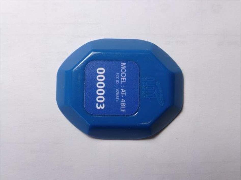
VZKAT4
Dec 08, 2013ACTIVE RFID TAG USED FOR PROTECTION OF ASSETS
Equipment Class
DSR - Part 15 Remote Control/Security Device Transceiver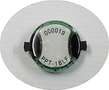
VZKPPT
Oct 24, 2012ACTIVE RFID TAG USED FOR LOCATION AND PERIMETER PROTECTION OF PEOPLE
Equipment Class
DSR - Part 15 Remote Control/Security Device Transceiver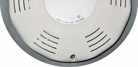
VZKTE
Aug 12, 2012GENERATOR OF LOW FREQUENCY FILED USED FOR DETECTION OF ACTIVE TAGS AT THE PORTAL
Equipment Class
DCD - Part 15 Low Power Transmitter Below 1705 kHz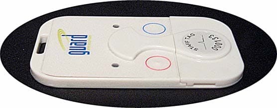
VZKST
Jan 26, 2012ACTIVE RFID TAG USED FOR LOCATION AND PERIMETER PROTECTION OF PEOPLE AND ASSETS
Equipment Class
DSR - Part 15 Remote Control/Security Device Transceiver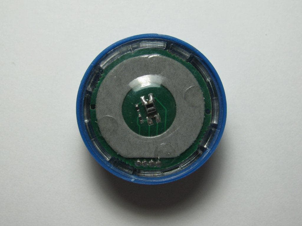
VZKAT
Oct 23, 2011ACTIVE RFID TAG USED FOR LOCATION AND PERIMETER PROTECTION OF ASSETS
Equipment Class
DSR - Part 15 Remote Control/Security Device Transceiver