VZKTEGENERATOR OF LOW FREQUENCY FILED USED FOR DETECTION OF ACTIVE TAGS AT THE PORTAL
Guard RFID Solutions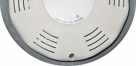
Click to zoom
Application Details
- Equipment Class
- DCD - Part 15 Low Power Transmitter Below 1705 kHz
- Date of Grant
- Aug 12, 2012
- Application Purpose
- Original Equipment
- Date of Application
- Aug 12, 2012
- Equipment Note
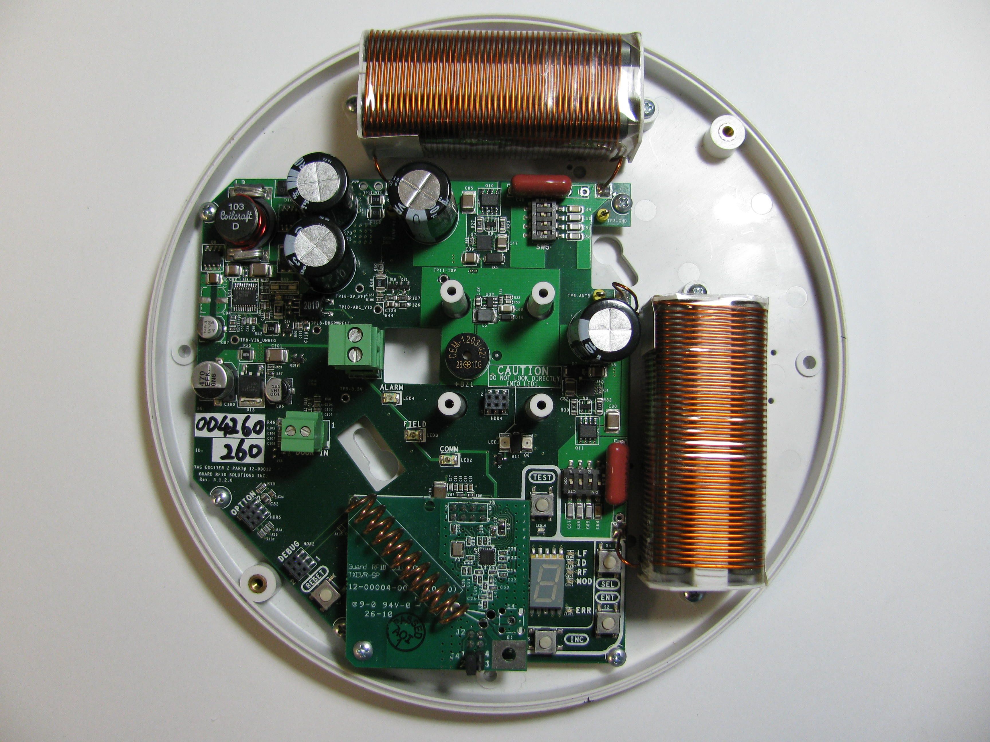
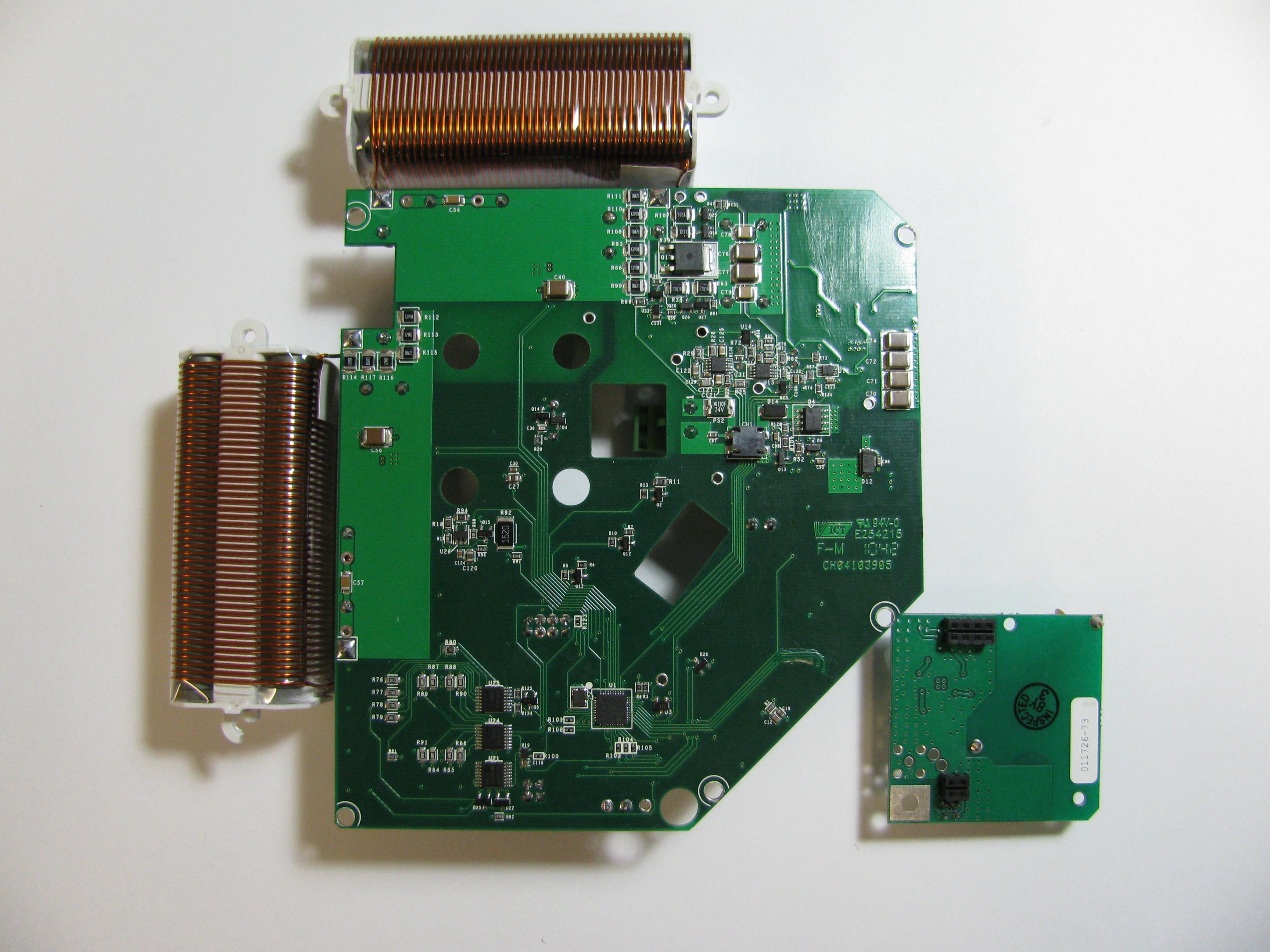
- GENERATOR OF LOW FREQUENCY FILED USED FOR DETECTION OF ACTIVE TAGS AT THE PORTAL
- Frequency Range
- 0.12500000 - 0.12500000
- Company
- Guard RFID Solutions
- Country
- Canada
Documents & Files
Document Text
Text extracted from the exhibit documents filed with the FCC. Open a document above to read the original.
Users Manual
Tag Exciter Installation Manual 07‐00051‐110 © 2010 GuardRFID Proprietary and Confidential Tag Exciter Installation Manual Patient Protection Infant Security Asset Management Tag Exciter Installation Manual 07‐00051‐110 © 2010 GuardRFID Proprietary and Confidential Copyrights and Trademarks ©2009 Guard RFID™ Solutions Inc. All Rights Reserved This manual is subject to copyright protection and all rights are reserved. Under copyright laws, the manual many not be copied or translated, in whole or in part, in any manner or format, without the written permission of Guard RFID™ Solutions Inc. All software in which Guard RFID™ Solutions Inc. or its affiliates hold a proprietary interest is also subject to copyright protection and all rights are reserved. No party may use or copy such software, in any manner or format, except to the extent that Guard RFID™ Solutions Inc., or an affiliate of Guard RFID™ Solutions Inc., grants them a license to do so. Trademarks Guard RFID is a registered trademark of Guard RFID™ Solutions, Inc. MySQL is a registered trademark of Oracle Corporation Windows is a registered trademark of Microsoft Revisions Specification subject to change without notice. Contact Information Guard RFID Solutions, Inc. #140 – 766 Cliveden Pl Delta, BC Canada V3M 6C7 Tele: 604.998.4018 Fax: 604.524.4018 www.guardrfid.com THIS DEVICE COMPLIES WITH PART 15 OF THE FCC RULES. OPERATION IS SUBJECT TO THE FOLLOWING TWO CONDITIONS: (1) THIS DEVICE MAY NOT CAUSE HARMFUL INTERFERENCE, AND (2) THIS DEVICE MUST ACCEPT ANY INTERFERENCE RECEIVED, INCLUDING INTERFERENCE THAT MAY CAUSE UNDESIRED OPERATION. NOTE: THE GRANTEE IS NOT RESPONSIBLE FOR ANY CHANGES OR MODIFICATIONS NOT EXPRESSLY APPROVED BY THE PARTY RESPONSIBLE FOR COMPLIANCE. SUCH MODIFICATIONS COULD VOID THE USER’S AUTHORITY TO OPERATE THE EQUIPMENT. Tag Exciter Installation Manual 07‐00051‐110 © 2010 GuardRFID Proprietary and Confidential Tag Exciter Installation Manual 07‐00051‐110 © 2010 GuardRFID Proprietary and Confidential Contents Installing the Tag Exciter...........................................................................................................................1 Determine Best Location ......................................................................................................................1 Using Tag Exciters to Determine Direction of Travel and Room Discrimination ..................................5 Connecting the Tag Exciter .......................................................................................................................8 Tag Exciter Inputs, Outputs, Indicators.................................................................................................8 Tag Exciter Power Connections.............................................................................................................9 Ensuring Compliance with RFI Rules and Regulations ..........................................................................9 Using the TE Disable (Door In) ............................................................................................................10 Tuning the Tag Exciter.............................................................................................................................11 User Interface .....................................................................................................................................11 User Interface Menu Navigation.........................................................................................................12 Setting the Proper TE Field Size ..........................................................................................................14 Setting the Tag Exciter ID....................................................................................................................15 Setting the RF Sensitivity ....................................................................................................................16 Setting the Modes...............................................................................................................................16 Reading the Error Codes .....................................................................................................................17 Tag Exciter Installation Manual 07‐00051‐110 © 2010 GuardRFID Proprietary and Confidential Tag Exciter Installation Manual 07‐00051‐110 © 2010 GuardRFID Proprietary and Confidential Installing the Tag Exciter Tag Exciters have three main functions. They are used to trigger an alarm at an egress point, pin point a tag’s location, and/or provide a reference point for when the tag changes floors via a stairwell or elevator. The Tag Exciter transmits a 125 KHz low frequency signal (field) that is detected by the RFID tag. Detection range of the Tag Exciter is adjustable from two to 18 feet. This section describes the two steps to installing the Tag Exciter: Determine the best location Install device. Determine Best Location The location of the Tag Exciter is critical to the proper operation of the system. An incorrectly placed tag exciter may cause nuisance alarms from nearby areas where tags are normally present, or fail to detect a tag when exiting through a doorway. NOTE: Only 2 TEs may be associated with a TRC in the Argus software or with an AtGuard Controller when configuring a gate. The Tag Exciter field can be visualized as a large sphere with the tag exciter in the centre of the sphere. As the Tag Exciter level is increased, so does the size of the sphere. The sphere ranges from 2 to 19 feet in diameter according to the setting. When a tag enters the exciter field, the Tag Exciter field is detected by the tag and events are generated by this action. An event may be an exit warning or alarm. For networked applications a Tag Exciter may be used for transitioning a tag from the previous floorplan to the present floorplan when moving vertically through a building, or trigger a c…
Text truncated - open the document above for the full version.
Cover Letter(s)
#140 – 760 Cliveden Place Delta, BC Canada V3M 6C7 T: 604.998.4018 F: 604.524.4018 www.guardrfid.com Aug 20, 2012 Federal Communications Commission Authorization and Evaluation Division Confidentiality Request regarding application for certification of FCC ID: (VZKTE). Pursuant to Sections 0.457 and 0.459 of the Commission’s Rules, we hereby request confidential treatment of information accompanying this application as outlined below: Exhibit Type File Name Schematic Data Modulation Block Diagram VZKTE_Schem.pdf VZKTE_OpDes.pdf VZKTE_BlockDia.pdf The above materials contain trade secrets and proprietary information not customarily released to the public. The public disclosure of these materials may be harmful to the applicant and provide unjustified benefits to its competitors. The applicant understands that pursuant to Section 0.457 of the Rules, disclosure of this application and all accompanying documentation will not be made before the date of the Grant for this application. Sincerely, Dalibor Pokrajac VP of Engineering Guard RFID Solutions Inc. 604-282-7584
External Photos
Prepared by: LabTest Certification Inc. Client: Guard RFID Solutions Inc. Date Issued: July 13, 2012 Report No.:10580-1E Project No: 10580 Revision No.: 0 Page 27 of 35 This document shall not be reproduced or utilized in any form or by any means, except in full, without the written approval of LabTest Certification Inc. DCN: 1034, Rev 4 APPENDIX B: EUT photos - EUT: Top View - EUT: Bottom View - EUT: Side View
ID Label/Location Info
Label Location of VZKTE
ID Label/Location Info
DESCRIPTION: FILE NAME: SIZE OF SCALE: DRAWN: CHECKED: DATE: REV SHEET REVISION DESCRIPTION ECR No. ANGULAR: DECIMAL: TOLERANCES UNLESS NOTED OTHERWISE 1:1 11 - BAZLUL KARIM 13-20020-220 (TAG EXCITER 2 FCC SN LABEL).pdf 2-20 - Changed FCC ID from VZKSP1 to VZKTE A DO NOT SCALE DRAWING 13-20020-220 PART NO. UNITS: July 09, 2012 INCHES FINISH: MATERIAL: TAG EXCITER 2 FCC SN LABEL - SEE ABOBE NOTES THIRD ANGLE PROJECTION #140-766 CLIVEDEN PLACE DELTA, BC, CANADA V3M 6C7 TEL: (604)-998-4018 fax: (604)-524-4018 www.guardrfid.com GUARD RFID SOLUTIONS INC. .XX± 0.10 .XXX± 0.005 .XXXX± 0.0005 ±0°-15° THIS DOCUMENT CONTAINS CONFIDENTIAL AND PROPRIETARY INFORMATION. THE REPRODUCTION, USE, OR DISCLOSURE IN ANY FORM WITHOUT AUTHORIZATION FROM GUARD RFID SOLUTIONS INC. TO ANY PARTY OTHER THAN THE INTENDED RECIPIENT IS STRICTLY PROHIBITED. NOTES: 1.) PRODUCT TO BE APPROVED BY GUARD RFID SOLUTIONS INC PRIOR TO PRODUCTION. 2.) OVERALL DIMENSIONS: 2.50" x 1.50" (L xW) 3.) COLOR: WHITE TEXT ON BLACK 4.) MATERIAL: TZ-261 TAPE FROM BROTHER INDUSTRIES LTD FOR P-TOUCH PRINTER © 2012 GuardRFID Proprietary and Con dential
Test Report
TEST REPORT For Guard RFID Solutions Inc. #140 – 766 Cliveden Place Delta, British Columbia V3M 6C7, Canada Date: __Aug. 10, 2012____ Report No.: __10580-1E_______ Revision No.: __1______________ Project No.: __10580__________ Equipment: __RFID Tag Exiter__ FCC ID: __VZKTE_________ ONE STOP GLOBAL CERTIFICATION SOLUTIONS 3133-20800 Westminster Hwy, Richmond, BC V6V 2W3, Canada Phone: 604-247-0444 Fax: 604-247-0442 www.labtestcert.com Prepared by: LabTest Certification Inc. Client: Guard RFID Solutions Inc. Date Issued: Aug. 10, 2012 Report No.:10580-1E Project No: 10580 Revision No.: 1 Page 2 of 41 This document shall not be reproduced or utilized in any form or by any means, except in full, without the written approval of LabTest Certification Inc. DCN: 1034, Rev 4 TABLE OF CONTENTS TEST REPORT ................................................................................................................................................ 3 General product information: ............................................................................................................................ 5 Frequencies...................................................................................................................................................... 5 List of ancillary and/or support equipment provided by the applicant .............................................................. 5 Description of Interface Cables for Testing ...................................................................................................... 5 Software and Firmware .................................................................................................................................... 6 Worst-case configuration and mode of operation during testing...................................................................... 6 Modifications Required for Compliance............................................................................................................ 6 Test Equipment Verified for function ................................................................................................................ 6 Measurement Uncertainty ................................................................................................................................ 6 Markings ........................................................................................................................................................... 7 Test Summary .................................................................................................................................................. 8 Antenna Requirement ...................................................................................................................................... 9 Test Limits..................................................................................................................................................... 9 Test Results: ................................................................................................................................................. 9 AC Power line Conducted Emission............................................................................................................... 10 Test Limits................................................................................................................................................... 10 Test Setup................................................................................................................................................... 10 Setup Block Diagram .................................................................................................................................. 11 Test Result.................................................................................................................................................. 11 Field Strength of Fundamental ....................................................................................................................... 16 Test Limits................................................................................................................................................... 16 Test Setup................................................................................................................................................... 17 Setup Block Diagram .................................................................................................................................. 17 Test Setup in Chamber ............................................................................................................................... 18 Test Result.................................................................................................................................................. 18 Radiated Emissions........................................................................................................................................ 20 Test Limits................................................................................................................................................... 20 Test Setup................................................................................................................................................... 21 Setup Block Diagram .................................................................................................................................. 22 Test Setup................................................................................................................................................... 22 Test Result.................................................................................................................................................. 22 20dB Bandwidth ............................................................................................................................................. 28 Test Limits.............................…
Text truncated - open the document above for the full version.
Test Report
TEST REPORT For Guard RFID Solutions Inc. #140 – 766 Cliveden Place Delta, British Columbia V3M 6C7, Canada Date: June 04, 2014 Report No.: 10580-1E Revision No.: 3 Project No.: 105802 Equipment: RFID Tag Exiter FCC ID: VZKTE IC ID: 9937A-TE ONE STOP GLOBAL CERTIFICATION SOLUTIONS 3133-20800 Westminster Hwy, Richmond, BC V6V 2W3, Canada Phone: 604-247-0444 Fax: 604-247-0442 www.labtestcert.com Prepared by: LabTest Certification Inc. Client: Guard RFID Solutions Inc. Date Issued: June 04, 2014 Report No.: 10580-1E Project No: 10580 Revision No.: 3 Page 2 of 41 This document shall not be reproduced or utilized in any form or by any means, except in full, without the written approval of LabTest Certification Inc. DCN: 1034, Rev 4 TABLE OF CONTENTS TEST REPORT ................................................................................................................................................ 3 General product information: ............................................................................................................................ 5 Frequencies ...................................................................................................................................................... 5 List of ancillary and/or support equipment provided by the applicant .............................................................. 5 Description of Interface Cables for Testing ...................................................................................................... 5 Software and Firmware .................................................................................................................................... 6 Worst-case configuration and mode of operation during testing ...................................................................... 6 Modifications Required for Compliance............................................................................................................ 6 Test Equipment Verified for function ................................................................................................................ 6 Measurement Uncertainty ................................................................................................................................ 6 Markings ........................................................................................................................................................... 7 Test Summary .................................................................................................................................................. 8 Antenna Requirement ...................................................................................................................................... 9 Test Limits ..................................................................................................................................................... 9 Test Results: ................................................................................................................................................. 9 AC Power line Conducted Emission ............................................................................................................... 10 Test Limits ................................................................................................................................................... 10 Test Setup ................................................................................................................................................... 10 Setup Block Diagram .................................................................................................................................. 11 Test Result .................................................................................................................................................. 11 Field Strength of Fundamental ....................................................................................................................... 16 Test Limits ................................................................................................................................................... 16 Test Setup ................................................................................................................................................... 17 Setup Block Diagram .................................................................................................................................. 17 Test Setup in Chamber ............................................................................................................................... 18 Test Result .................................................................................................................................................. 18 Radiated Emissions ........................................................................................................................................ 20 Test Limits ................................................................................................................................................... 20 Test Setup ................................................................................................................................................... 21 Setup Block Diagram .................................................................................................................................. 22 Test Setup ................................................................................................................................................... 22 Test Result .................................................................................................................................................. 22 20dB Bandwidth ............................................................................................................................................. 28 Test Limits .....................................................…
Text truncated - open the document above for the full version.
Test Setup Photos
Prepared by: LabTest Certification Inc. Client: Guard RFID Solutions Inc. Date Issued: Aug. 10, 2012 Report No.:10580-1E Project No: 10580 Revision No.: 1 Page 34 of 41 This document shall not be reproduced or utilized in any form or by any means, except in full, without the written approval of LabTest Certification Inc. DCN: 1034, Rev 4 APPENDIX C: Test setup photos - Test configuration for AC Power Line conducted emission Prepared by: LabTest Certification Inc. Client: Guard RFID Solutions Inc. Date Issued: Aug. 10, 2012 Report No.:10580-1E Project No: 10580 Revision No.: 1 Page 35 of 41 This document shall not be reproduced or utilized in any form or by any means, except in full, without the written approval of LabTest Certification Inc. DCN: 1034, Rev 4 - Test configuration for LF Testing, 125kHz to 30MHz Prepared by: LabTest Certification Inc. Client: Guard RFID Solutions Inc. Date Issued: Aug. 10, 2012 Report No.:10580-1E Project No: 10580 Revision No.: 1 Page 36 of 41 This document shall not be reproduced or utilized in any form or by any means, except in full, without the written approval of LabTest Certification Inc. DCN: 1034, Rev 4 - Test configuration for Radiated Emission, 30 MHz to 1GHz Prepared by: LabTest Certification Inc. Client: Guard RFID Solutions Inc. Date Issued: Aug. 10, 2012 Report No.:10580-1E Project No: 10580 Revision No.: 1 Page 37 of 41 This document shall not be reproduced or utilized in any form or by any means, except in full, without the written approval of LabTest Certification Inc. DCN: 1034, Rev 4 - Test setup on Table
Contact Information
Applicant
Dalibor Pokrajac(VP of Engineering)
Test Firm
LabTest Certification Inc.Kavinder Dhillon
Technical Specifications
| # | Rule Parts | Frequency Range | Power Output |
|---|---|---|---|
| 1 | 15C | 0.125 MHz - 0.125 MHz | - |
Other Applications from Guard RFID Solutions
VZKST4
Jan 03, 2023Guard RFID WiFi staff/employee tag
Equipment Class
DTS - Digital Transmission System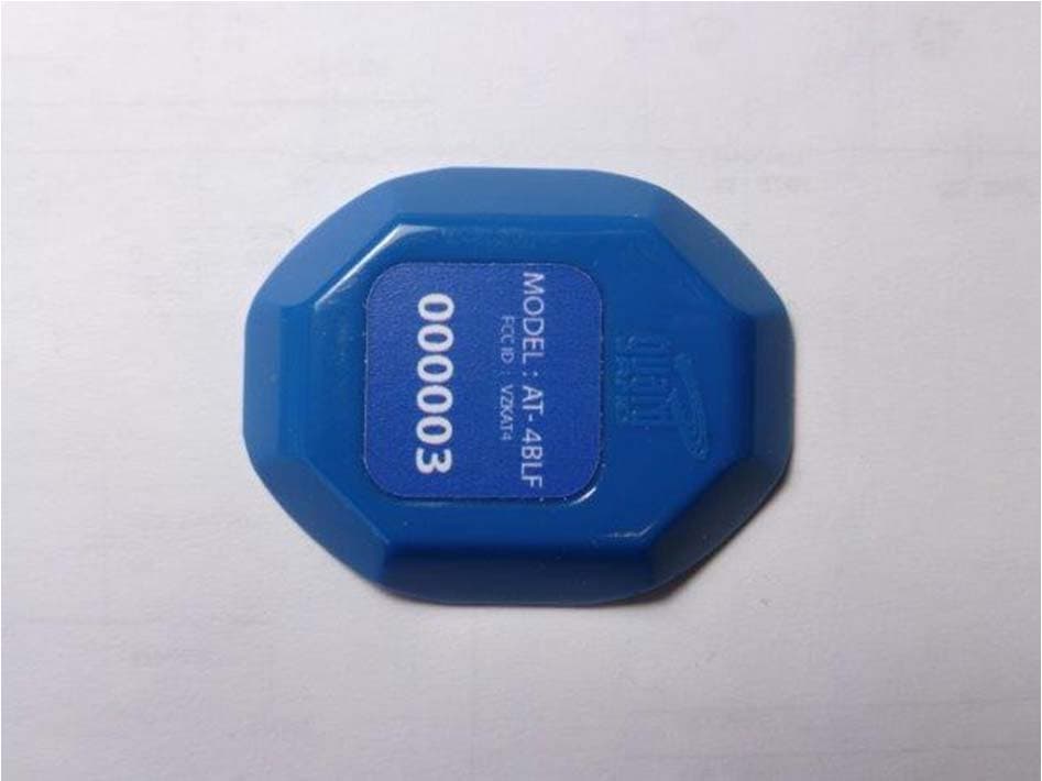
VZKAT4
Dec 08, 2013ACTIVE RFID TAG USED FOR PROTECTION OF ASSETS
Equipment Class
DSR - Part 15 Remote Control/Security Device Transceiver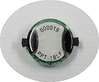
VZKPPT
Oct 24, 2012ACTIVE RFID TAG USED FOR LOCATION AND PERIMETER PROTECTION OF PEOPLE
Equipment Class
DSR - Part 15 Remote Control/Security Device Transceiver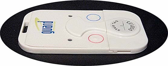
VZKST
Jan 26, 2012ACTIVE RFID TAG USED FOR LOCATION AND PERIMETER PROTECTION OF PEOPLE AND ASSETS
Equipment Class
DSR - Part 15 Remote Control/Security Device Transceiver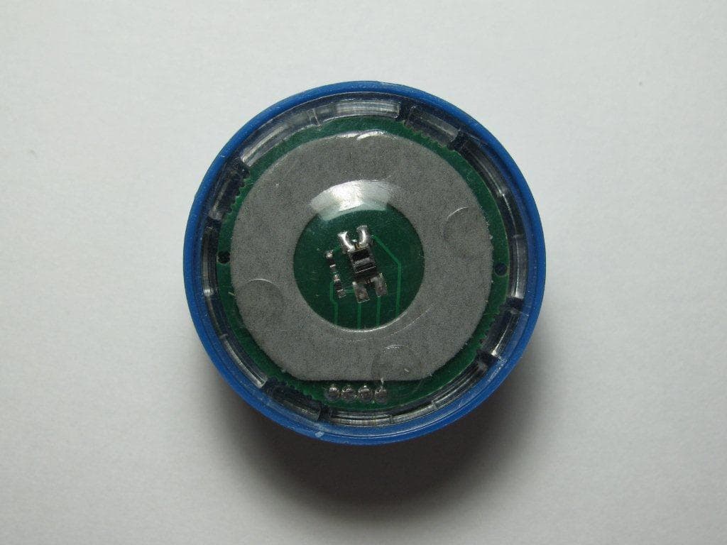
VZKAT
Oct 23, 2011ACTIVE RFID TAG USED FOR LOCATION AND PERIMETER PROTECTION OF ASSETS
Equipment Class
DSR - Part 15 Remote Control/Security Device Transceiver