W59PWFC2PRO-WAV Wi-Fi Range Extender System
Legrand AV Inc.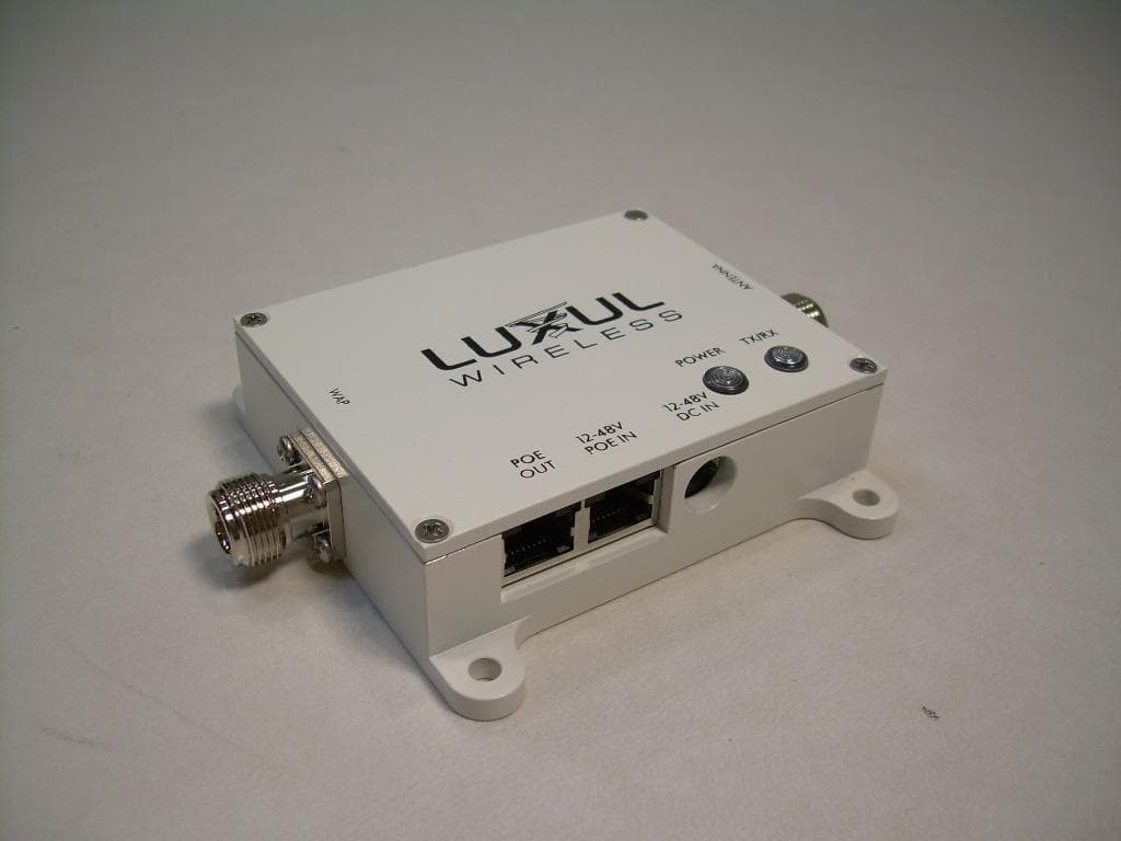
Click to zoom
Application Details
- Equipment Class
- DTS - Digital Transmission System
- Date of Grant
- Aug 16, 2010
- Application Purpose
- Original Equipment
- Date of Application
- Aug 16, 2010
- Equipment Note
- PRO-WAV Wi-Fi Range Extender System
- Frequency Range
- 2412.00000000 - 2462.00000000
- Company
- Legrand AV Inc.
- Country
- United States
Documents & Files
Document Text
Text extracted from the exhibit documents filed with the FCC. Open a document above to read the original.
Users Manual
USER GUidE PRo-WAV™ Wi-Fi RAnGE ExtEndER SYStEM FoR USE With thE nEtGEAR WG103 PRoSAFE® 802.11G WiRElESS AccESS Point ModEl nUMbER: PW-Fc2 - SinGlE AntEnnA PW-Fc2 - dUAl AntEnnA Pro-WAV Wi-Fi rAnge extender SyStem model number: PW-FC2 inStAllAtion guide © 2010 by Luxul Wireless, Inc. All rights reserved. No part of this publication may be modified or adapted in any way, for any purposes without permission in writing from Luxul Wireless, Inc. (Luxul). The material in this manual is subject to change without notice. Luxul reserves the right to make changes to any product to improve reliability, function, or design. No license is granted, either expressly or by implication or otherwise under any Luxul Wireless, Inc., intellectual property rights. An implied license only exists for equipment, circuits and subsystems contained in Luxul products. Antenna for broadband wireless communications This product is covered by one or more U.S. and foreign patents. Patents: 7,379,717 6,606,075, 6,373,448, other patents pending Pro-WAV Wi-Fi rAnge extender SyStem model number: PW-FC2 FCC ID: W59PWFC2 IC: 8584A-PWFC2 netgeAr WireleSS ACCeSS Point model number: Wg103 FCC ID: PY308400097 IC: 4054A-08400097 Luxul Wireless, Inc. 357 South 670 West, Suite 160 Lindon, UT 84042 www.luxulwireless.com ShocK-WAV SiGnAl booStER USER GUidE 1 ContentS 1 - introduCtion . . . . . . . . . . . . . . . . . . . . . . . . . . . . . . . . . . . . . . . . . . . . . . . . . . . . . . . . . . . . 2 1.1 Document Conventions ................................................................2 1.2 Warnings..............................................................................2 1.3 Site Preparation .......................................................................3 1.4 Professional Installation Considerations.................................................3 2 - SPeCiFiCAtionS............................................................4 2.1 SHOCK-WAV™ WI-FI SIGNAL BOOSTER SPECIFICATIONS.................................4 2.2 X-WAV™ FLAT PANEL ANTENNA SPECIFICATIONS .......................................4 3 - getting StArted..........................................................5 3.1 Precautions ...........................................................................5 3.2 Package Contents .....................................................................5 3.3 Additional Items Required .............................................................6 4 - inStAllAtion ProCedureS................................................6 4.1 Removing the Stock Antenna from the Netgear WG103 ..................................6 4.1 Connecting the PW-FC2 - Single Antenna to the Netgear WG103 .........................7 4.2 Connecting the PW-FC2 - DUAL Antenna to the Netgear WG103.........................7 4.3 Connecting Direct Power and Data Source cables .......................................8 4.4 Connecting POE Power and Data Source cables .........................................8 4.5 Optional POE Injector.................................................................9 5 - AntennA PlACement .....................................................9 5.1 Antenna Deployment..................................................................9 6 - regulAtory ComPliAnCe ................................................11 6.1 Health and Safety Recommendations..................................................11 6.2 RF Exposure Guidelines...............................................................11 6.3 Radio Frequency Interference Requirements—FCC .....................................12 6.4 Radio Transmitters (Part 15) ...........................................................13 6.5 Industry Canada ( RSS-Gen Issue 2)....................................................13 7 - SAleS And SuPPort ContACtS............................................13 2 1 - introduCtion The Luxul Wireless Pro-WAV Wi-Fi Range Extender System is designed to complement and enhance the performance of the Netgear WG103 Wireless Access Point (WAP). When com- bined with the WG103 and X-WAV XW-24-FP7 Flat Panel Antenna, it delivers up to the maximum approved transmit power, resulting in a farther reaching and higher performing network. Luxul Wireless Pro-WAV Wi-Fi Range Extender System feature patented RF technology that dynamically optimizes output strength and provides the cleanest, most consistent signal amplification available for Wi-Fi networks. Designed for bidirectional signal amplification, Shock-WAV Wi-Fi Signal Boosters utilize patented Digital Automatic Gain Control (D-AGC) tech- nology that actively monitors the incoming signal from each packet and makes adjustments so that the output signal maintains constant power levels, ensuring the cleanest and most consistent RF signal possible. 1.1 doCument ConVentionS The following graphical alerts are used in this document to indicate notable situations: NOTE: Tips, hints, or special requirements that you should take note of. CAUTION: Care is required. Disregarding a caution can result in data loss or equipment malfunction. WARNING!: Indicates a condition or procedure that could result in personal injury or equipment damage. 1.2 WArningS • Read all installation instructions and site survey reports, and verify correct equipment installation before connecting the Shock-WAV Wi-Fi Signal Booster or WG103 to its power source. • Remove jewelry and watches before installing this equipment. • Verify that the unit is grounded before connecting it to the power source. • Verify that any device connected to this unit is properly wired and grounded. • Connect all power cords to a properly wired and grounded electrical circuit. • Verify that the electrical circuits have appropriate overload protection. • Attach only approved power cords to the device. ShocK-WAV SiGnAl booStER USER GUidE 3 • Verify that the power connector and socket are accessible at all times during the operation of the equipment. • Do not work with power circuit…
Text truncated - open the document above for the full version.
External Photos
Front Side View of the EUT Back Side View of the EUT
Internal Photos
Internal View of the EUT Internal View of the EUT with RF Shield Removed View of the Trace Side of the EUT PCB
RF Exposure Info
RF Exposure Evaluation Declaration Product Name: Shock-Wav TM Indoor Wi-Fi Signal Booster Model Number: PW-FC2 FCC ID: W59PWFC2 Applicant: Luxul Wireless Address: 357 S 670 W Suite 160 Lindon UT 84042 USA Date of Declaration: 30 July 2010 The declaration results relate only to the samples calculated. RF Exposure Evaluation Limits Per FCC 1.1310 Table 1B, the maximum permissible RF exposure for an uncontrolled environment is 1 mW/cm 2 for the frequencies used in this device. The worst-case power for the antenna at the center frequency of the band of operation is used for the calculation below. The power density at a 20 cm distance is shown for each of the antenna options. As shown, the calculated power density is below the FCC’s limit for Class B exposure of 1mW/cm 2 . The actual power density for the EUT calculated as shown below. Pd=(Pout*G)/(4*pi*r 2 ) Where Pd = power density in mW/cm 2 Pout = output power to antenna in mW G = gain of antenna in linear scale Pi = 3.1416 R = distance between observation point and the center of the radiator in cm NOTICE: Radiation Exposure Statement This equipment shall only be installed and operated with the antenna types shown above and installed with a minimum of 20 cm of separation distance between the antenna and all persons during normal operation. Frequency A ntennaModulationA ntennaNumericPowerSeparationPower Density MHzTypeType Max Linear Gain (dBi)Ga in( mW )Dis t a n c e ( c m) (mw/cm 2 ) 2437Patch11b4.02.5676.10200.3379 2437Patch11g4.02.5537.00200.2684 2437Omni11b5.03.2676.10200.4253 2437Omni11g5.03.2537.00200.3378 2437 Dual Patch11b7.05.0676.10200.6757 2437Dual Patch11g7.05.0537.00200.5367
Test Report
Nemko-CCL, Inc. 1940 West Alexander Street Salt Lake City, UT 84119 801-972-6146 Test Report Certification Test Of: PW-FC2 FCC ID: W59PWFC2 Test Specifications: FCC PART 15, Subpart C Test Report Serial No: 154305-2.1 Applicant: Luxul Wireless 357 South 670 West, Suite 160 Lindon, UT 84042 Date of Test: June 24, 2010 and July 6, 2010 Issue Date: July 28, 2010 Accredited Testing Laboratory By: NVLAP Lab Code 100272-0 Nemko-CCL, Inc. TEST REPORT: 154305-2.1 FCC ID#: W59PWFC2 Page 2 of 72 2 CERTIFICATION OF ENGINEERING REPORT This report has been prepared by Nemko-CCL, Inc. to document compliance of the device described below with the requirements of Federal Communications Commission (FCC) Part 15, Subpart C. This report may be reproduced in full, partial reproduction may only be made with the written consent of the laboratory. The results in this report apply only to the sample tested. - Applicant: Luxul Wireless - Manufacturer: Luxul Wireless - Brand Name: Luxul - Model Number: PW-FC2 - FCC ID Number: W59PWFC2 On this 28 th day of July 2010, I, individually, and for Nemko-CCL, Inc., certify that the statements made in this engineering report are true, complete, and correct to the best of my knowledge, and are made in good faith. Although NVLAP has recognized that the Nemko-CCL, Inc. EMC testing facilities are in good standing, this report must not be used to claim product certification, approval, or endorsement by NVLAP, NIST, or any agency of the federal government. Nemko-CCL, Inc. Tested by: Norman P. Hansen EMC Technician Nemko-CCL, Inc. TEST REPORT: 154305-2.1 FCC ID#: W59PWFC2 Page 3 of 72 3 TABLE OF CONTENTS PAGE SECTION 1.0 CLIENT INFORMATION .................................................................................4 SECTION 2.0 EQUIPMENT UNDER TEST (EUT) .................................................................5 SECTION 3.0 TEST SPECIFICATION, METHODS & PROCEDURES .............................8 SECTION 4.0 OPERATION OF EUT DURING TESTING ..................................................14 SECTION 5.0 SUMMARY OF TEST RESULTS ...................................................................15 SECTION 6.0 MEASUREMENTS, EXAMINATIONS AND DERIVED RESULTS ..........16 APPENDIX 1 TEST PROCEDURES AND TEST EQUIPMENT ..........................................52 APPENDIX 2 PHOTOGRAPHS ................................................................................................60 Nemko-CCL, Inc. TEST REPORT: 154305-2.1 FCC ID#: W59PWFC2 Page 4 of 72 4 SECTION 1.0 CLIENT INFORMATION 1.1 Applicant: Company Name: Luxul Wireless 357 South 670 West, Suite 160 Lindon, UT 84042 Contact Name: Vaughn Staheli Title: V.P. Engineering 1.2 Manufacturer: Company Name: Luxul Wireless 105 South 1380 West, Unit 1 Lindon, UT 84042 Contact Name: Vaughn Staheli Title: V.P. Engineering Nemko-CCL, Inc. TEST REPORT: 154305-2.1 FCC ID#: W59PWFC2 Page 5 of 72 5 SECTION 2.0 EQUIPMENT UNDER TEST (EUT) 2.1 Identification of EUT: Brand Name: Luxul Model Number: PW-FC2 Serial Number: SW1015820 2.2 Description of EUT: The PW-FC2 is a WiFi Signal Booster for use with the Netgear WG103 Access Point. The PW-FC2 provides N connectors for RF input and output. Power is provided to the PW-FC2 by a Shenzhen Flypower Technology Co. Ltd. PS48IEIAY1000S power supply thru an Engenius EBU-101-01 POE injector. The PW-FC2 was tested using 3 antenna configurations; a Luxul 5dBi omni directional antenna, aLuxul XW-24-FP7 antenna or dual Luxul XW-24-FP7 antennas. The Luxul XW-24-FP7 antenna is a 4 dBi antenna. The Netgear WG103 can transmit using either 802.11b or 802.11g protocol. The Netgear WG103 uses 11 channels in the 2400 to 2483.5 MHz frequency range. See the table below. Channel Frequency (MHz) Channel Frequency (MHz) Channel Frequency (MHz) 1 2412 5 2432 9 2452 2 2417 6 2437 10 2457 3 2422 7 2442 11 2462 4 2427 8 2447 The PW-FC2 is designed to be used only with the Netgear WG103 Access Point. The PW-FC2 uses the Engenius EBU-101-01 POE injector and Shenzhen Flypower Technology Co. Ltd. PS48IEIAY1000S power supply. These devices are sold with the PW-FC2 as a system. Testing was performed at the upper, middle, and lower channels using both “B” and “G” protocols and using each of the 3 antenna configurations. This report covers the circuitry of the devices subject to FCC Part 15, Subpart C. The circuitry of the device subject to FCC Subpart B is covered in Nemko-CCL, Inc. report #154305- 1.1. 2.3 EUT and Support Equipment: The FCC ID numbers for all the EUT and support equipment used during the test are listed below: Nemko-CCL, Inc. TEST REPORT: 154305-2.1 FCC ID#: W59PWFC2 Page 6 of 72 6 Brand Name Model Number Serial Number FCC ID Number or Compliance Description Name of Interface Ports / Interface Cables BN: Luxul MN: PW-FC2 (Note 1) SN: SW1015820 W59PWFC2 WiFi Signal Booster See Section 2.4 BN: Netgear MN: WG103 SN: 20B103540015A PY308400097 Access Point Ethernet/Cat 5 cable w/RJ45 connectors (Note 2) RF/Coax cable (Note 2) BN: Engenius MN: EBU-101-01 SN: None DoC POE Injector Ethernet with Power/Cat 5 cable w/RJ45 connectors (Note 2) Ethernet/Cat 5 cable w/RJ45 connectors BN: TRENDnet MN: TEG-S50TXE SN: None DoC 5 port LAN switch Ethernet/Cat 5 cable w/RJ45 connectors BN: Toshiba MN: Satelite SN: None DoC Laptop Computer Ethernet/Cat 5 cable w/RJ45 connectors Note: (1) EUT (2) Interface port connected to EUT (See Section 2.4) The support equipment listed above was not modified in order to achieve compliance with this standard. Nemko-CCL, Inc. TEST REPORT: 154305-2.1 FCC ID#: W59PWFC2 Page 7 of 72 7 2.4 Interface Ports on EUT: Name of Ports No. of Ports Fitted to EUT Cable Descriptions/Length WAP 1 N to RP-SMA coax/10 inches POE Out 1 Cat5e with RJ45 connectors/12 inches 12-48V POE In 1 Cat 5e with RJ45 connectors/1 meter 2.5 Modification Incorporated/Special Accessories on EUT: The following modifications were made to the Shenzhen Flypower Technology Co. Ltd. PS48IEIAY1000S power supply cord at the POE injecto…
Text truncated - open the document above for the full version.
Test Setup Photos
Front View Radiated Emissions Configuration Using POE Power and 5 dBi Omni Antenna Back View Radiated Emissions Configuration Using POE Power and 5 dBi Omni Antenna Front View Radiated Emissions Configuration Using POE Power and Single FP7 Antenna Front View Radiated Emissions Configuration Using POE Power and Dual FP7 Antennas Front View Radiated Emissions Configuration Using External Power to the Access Point and 5 dBi Omni Antenna Back View Radiated Emissions Configuration Using External Power to the Access Point and 5 dBi Omni Antenna Front View of Worst-Case Conducted Emission Configuration Back View of Worst-Case Conducted Emission Configuration
Contact Information
Applicant
Vaughn Staheli(Senior Director, Engineering)
Test Firm
Nemko-CCL, Inc.Thomas Jackson
Technical Specifications
| # | Rule Parts | Frequency Range | Power Output |
|---|---|---|---|
| 1 | 15C | 2.41 GHz - 2.46 GHz | 676.10 mW |
Other Applications from Legrand AV Inc.
W59VAD50909
Sep 04, 2024Venture VideoBAR
Equipment Class
DTS - Digital Transmission System
W59AP3025
Jan 08, 2023AC1300 Dual-Band Outdoor Wireless Access Point
Equipment Class
DTS - Digital Transmission System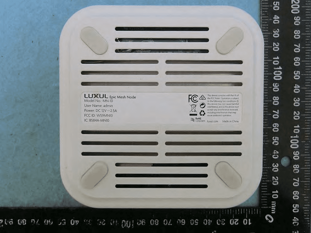
W59MN10
Mar 05, 2020Epic Mesh Node
Equipment Class
DSS - Part 15 Spread Spectrum Transmitter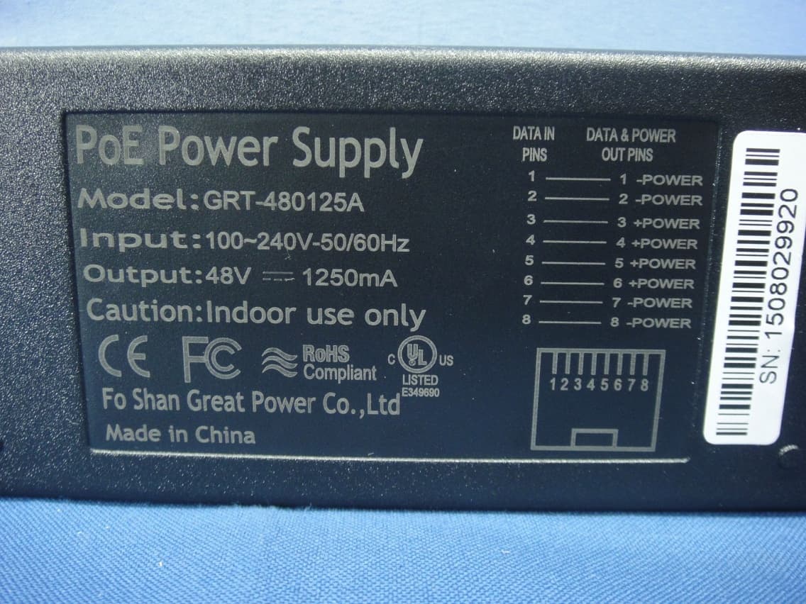
W59XAP1510
Sep 24, 2015High Power AC1900 Dual-Band Wireless AP
Equipment Class
NII - Unlicensed National Information Infrastructure TX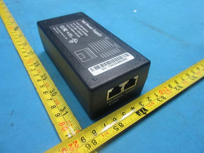
W59XAP1240
Aug 20, 2015High Power Wireless 300N Outdoor AP
Equipment Class
DTS - Digital Transmission System