W59XWR1750Dual Band Wireless AC1750 Gigabit Router
Legrand AV Inc.
Click to zoom
Application Details
- Equipment Class
- NII - Unlicensed National Information Infrastructure TX
- Date of Grant
- Jan 01, 2014
- Application Purpose
- Original Equipment
- Date of Application
- Dec 24, 2013
- Equipment Note
- Dual Band Wireless AC1750 Gigabit Router
- Frequency Range
- 5180.00000000 - 5240.00000000
- Company
- Legrand AV Inc.
- Country
- United States
Documents & Files
Document Text
Text extracted from the exhibit documents filed with the FCC. Open a document above to read the original.
Users Manual
Simply Connected Quick Install Guide XWR-1750 Dual Band Wireless AC1750 Gigabit Router Use the XWR-1750 to: Deliver Next Generation 802.11ac Gigabit Wi-Fi with Speeds up to 1750Mbps Maximize Data Rates with Concurrent Dual-Band (2.4GHz and 5GHz) Technology Optimize VoIP, Streaming Media and Other Demanding Applications Create a Secure Guest Network Provide an Affordable High Performance Network AC1750 Gigabit RouterAC1750 Gigabit Router Use the XWR-1750 to: Quick Install Guide XWR-1750 14203 Minuteman Drive, Suite 201, Draper, UT 84020-1685 luxul.com | 801-822-5450 2 DUAL BAND WIRELESS AC1750 GIGABIT ROUTER Model Number: XWR-1750 FCC ID: W59XWR1750 Quick Install Guide © 2013 Luxul. All Rights Reserved. No part of this publication may be modified or adapted in any way, for any purposes without permission in writing from Luxul. The material in this manual is subject to change without notice. Luxul reserves the right to make changes to any product to improve reliability, function, or design. No license is granted, either ex- pressly or by implication or otherwise under any Luxul intellectual property rights. An implied license only exists for equipment, circuits and subsystems contained in this or any Luxul product. DOCUMENT CONVENTIONS These graphical alerts are used in this document to indicate notable situations: NOTE: Tips, hints, or special requirements that you should take note of. CAUTION: Care is required. Disregarding a caution can result in data loss or equipment malfunction. WARNING!: Indicates a condition or procedure that could result in personal injury or equipment damage. FCC COMPLIANCE This device complies with Part 15 of the FCC Rules. Operation is subject to the following two conditions: (1) this device may not cause harmful interference, and (2) this device must accept any interference received, including interference that may cause undesired operation. CONTACT LUXUL Sales P: (801) 822-5450 E: [email protected] Technical Support P: (801) 822-5450 E: [email protected] Simply Connected © 2013 Luxul. All Rights Reserved. Other trademarks and registered trademarks are the property of their respective owners 3 PACKAGE CONTENTS The following items should be included in the box: XWR-1750 Dual Band Wireless AC1750 Gigabit Router 3 Dual Band RPSMA Male Antennas Ethernet Cable Power Adaptor Quick Installation Guide NOTE: If any of the listed items are missing or damaged, please contact the reseller from whom you purchased for return/replacement. HARDWARE DESCRIPTION XWR-1750 LED Indicators IndicatorNameStatusFunction WPS LED ONIndicates the XWR-1750 is ready for WPS pairing. 5GHzONIndicates a 5GHz wireless network is broadcasting. 2.4GHzONIndicates a 2.4GHz network is broadcasting. 1-4 LEDONIndicates a device is connected to the Ethernet port number. FLASHINGindicates data packets are being transmitted to the connected device. Internet LED ONIndicates the XWR-1750 is connected to the ISP. FLASHINGIndicates data packets are being transmitted USB LED ONIndicates a USB enabled device is connected and configured. System LED ONIndicates the XWR-1750 is booting. FLASHINGIndicates the XWR-1750 is operating normally. OFFIndicates the XWR-1750 will not boot Power LED ONON indicates power is applied to the XWR-1750. OFFIndicates power is not applied to the XWR-1750. For future feature additions Quick Install Guide XWR-1750 14203 Minuteman Drive, Suite 201, Draper, UT 84020-1685 luxul.com | 801-822-5450 4 Rear Panel XWR-1750 Rear Panel View Antenna Ports: 3 RPSMA female antenna ports to connect the included antennas Power Input: Power adapter included NOTE: To hard reboot the router, remove the power adapter. Wait 10 seconds and re-apply power. USB 1 -2 Ports: 2 USB 2.0 ports for connecting USB based printers and hard drives WAN Port: 1 Black RJ-45 Ethernet Port for Internet connection LAN 1 - 4 Ports: 4 Green RJ-45 Ethernet Ports for connecting to the local network NOTE: It is recommended that a Luxul switch be used in conjunction with the XWR-1750 to increase number of local ports available. WPS/Reset Button: Used to confi gure WPS or restore factory default settings CAUTION: Holding the WPS button longer than 10 seconds will result in a factory reset Simply Connected © 2013 Luxul. All Rights Reserved. Other trademarks and registered trademarks are the property of their respective owners 5 PREPARING FOR INSTALLATION System Requirements Computer supporting TCP/IP and equipped with a Web browser. Supported Web browser versions include I.E. 9.0, Firefox 3.6, Safari 5.0, Chrome 6.0, Opera 10.6 and up. The Web browser is used to confi gure the XWR-1750. Power must be AC 100-240V~ 1.0A 50/60Hz. XWR-1750 INSTALLATION Desktop Installation For use as a desktop device, position the XWR-1750 on a desk or other horizontal surface with adequate room around the XWR-1750 for ventilation. Wall Installation The XWR-1750 Is keyholed to allow installation on a wall or ceiling. Use the Mounting Pattern (Page 8-9) for keyhole alignment. Hardware Setup Attach Antennas: Connect the included Dual Band Antennas to all three antenna ports. NOTE: All three antennas should be installed prior to powering up the XWR-1750 and are required for optimal performance. WAN Connection: Connect the Ethernet cable from the modem/router equipment provided by your Internet Service Provider (ISP) to the black WAN port of the XWR-1750. AC Power: Connect the included AC Adapter to the XWR-1750 fi rst and then to the AC outlet. Quick Install Guide XWR-1750 14203 Minuteman Drive, Suite 201, Draper, UT 84020-1685 luxul.com | 801-822-5450 6 CONFIGURATION Default IP Address The XWR-1750 default IP address is 192.168.0.1. This address can be changed. However, for hassle free installation of other XenConnect™ plug and play Luxul devices, it is recommended that the default IP value be maintained. Parameter:Default Value Default IP address:192.168.0.1 Default user name: admin Default password:admin Conne…
Text truncated - open the document above for the full version.
Cover Letter(s)
CERTIFICATE OF COMPLIANCE Authorized under Declaration of Conformity according to 47 CFR, Part 2 and Part 15 of the FCC Rules. The product listed in follows was (were) tested in the Neutron EMC Laboratory to comply with the criteria limits Class B of conducted and radiated emissions of the Technical Standards FCC Part 15, Subpart B, established by the FCC, USA. Date of Issue Dec. 13, 2013 Equipment Dual Band Wireless AC1750 Gigabit Router Model Name XWR-1750 Brand Name Luxul Xen™ Applicant Luxul Wireless Address 14203 Minuteman Drive, Suite 201, Draper, UT USA Standard(s) FCC Part 15, Subpart B: 2012 ANSI C63.4 -2009 Report(s) NEI-FCCE-1-1308C047 The test data, data evaluation, and equipment configuration contained in our test report(s) above was(were) obtained utilizing the test procedures, test instruments, test sites that has been accredited by the Authority of TAF according to the ISO-17025 quality assessment standard and technical standard(s). The test data contained in the referenced test report relate only to the EUT sample and item(s) tested. Andy Chiu Authorized Signatory Neutron Engineering Inc. B1, No.37, Lane 365, Yang Guang St., NeiHu District 114., Taipei, Taiwan TEL:+886-2-2657-3299 FAX:+886-2-2657-3331
External Photos
Neutron Engineering Inc. Project No.: 1308C047 Page 2 of 15 Neutron Engineering Inc. Project No.: 1308C047 Page 3 of 15 Neutron Engineering Inc. Project No.: 1308C047 Page 4 of 15 Neutron Engineering Inc. Project No.: 1308C047 Page 5 of 15 Neutron Engineering Inc. Project No.: 1308C047 Page 6 of 15
ID Label/Location Info
Label Location
Internal Photos
Neutron Engineering Inc. Project No.: 1308C047 Page 7 of 15 Neutron Engineering Inc. Project No.: 1308C047 Page 8 of 15 Neutron Engineering Inc. Project No.: 1308C047 Page 9 of 15 Neutron Engineering Inc. Project No.: 1308C047 Page 10 of 15 Neutron Engineering Inc. Project No.: 1308C047 Page 11 of 15 Neutron Engineering Inc. Project No.: 1308C047 Page 12 of 15 Neutron Engineering Inc. Project No.: 1308C047 Page 13 of 15 Neutron Engineering Inc. Project No.: 1308C047 Page 14 of 15 Neutron Engineering Inc. Project No.: 1308C047 Page 15 of 15
RF Exposure Info
Neutron Engineering Inc. FCC RF EXPOSURE REPORT FCC ID: W59XWR1750 Project No. : 1308C047 Equipment : Dual Band Wireless AC1750 Gigabit Router Model : XWR-1750 Applicant : Luxul Wireless Address : 14203 Minuteman Drive, Suite 201, Draper, UT USA According: : FCC Guidelines for Human Exposure IEEE C95.1 Neutron Engineering Inc. No.3, Jinshagang 1st Road, ShiXia, Dalang Town, Dong Guan, China. TEL : (0769) 8318-3000 FAX : (0769) 8319-6000 Neutron Engineering Inc. MPE CALCULATION METHOD: Calculation Method of RF Safety Distance: where: S = power density P = power input to the antenna G = power gain of the antenna in the direction of interest relative to an isotropic radiator R = distance to the center of radiation of the antenna Ant. Brand M/N Antenna TypeConnector Gain (dBi) Note 0 Q5100 Dipole AntennaN/A 5.0 TX/RX 1 Q5100 Dipole AntennaN/A 5.0 TX/RX 2 Q5100 Dipole AntennaN/A 5.0 TX/RX TEST RESULTS EUT: Dual Band Wireless AC1750 Gigabit Router Model Name : XWR-1750 Temperature: 25 °C Relative Humidity: 58 % Pressure: 1012 hPa Test Voltage : AC 120V/60Hz Test Mode : Band 1/TX A Mode/CH36, CH40, CH48 Antenna Gain (dBi) Antenna Gain (numeric) Peak Output Power (dBm) Peak Output Power (mW) Power Density (S) (mW/cm 2 ) Limit of Power Density (S) (mW/cm 2 ) Te s t Result 5 3.1623 14.9 30.9030 0.019451380.0501 Complies 5 3.1623 14.92 31.0456 0.019541160.0501 Complies 5 3.1623 14.98 31.4775 0.019813010.0501 Complies Neutron Engineering Inc. EUT: Dual Band Wireless AC1750 Gigabit Router Model Name : XWR-1750 Temperature: 25 °C Relative Humidity: 58 % Pressure: 1012 hPa Test Voltage : AC 120V/60Hz Test Mode : Band 1/TX N20 Mode/CH36, CH40, CH48-ANT 0 Antenna Gain (dBi) Antenna Gain (numeric) Peak Output Power (dBm) Peak Output Power (mW) Power Density (S) (mW/cm2) Limit of Power Density (S) (mW/cm2) Te s t Result 5 3.1623 8.95 7.8524 0.004942540.0501 Complies 5 3.1623 8.99 7.9250 0.004988270.0501 Complies 5 3.1623 9.01 7.9616 0.005011300.0501 Complies EUT: Dual Band Wireless AC1750 Gigabit Router Model Name : XWR-1750 Temperature: 25 °C Relative Humidity: 58 % Pressure: 1012 hPa Test Voltage : AC 120V/60Hz Test Mode : Band 1/TX N20 Mode/CH36, CH40, CH48-ANT 1 Antenna Gain (dBi) Antenna Gain (numeric) Peak Output Power (dBm) Peak Output Power (mW) Power Density (S) (mW/cm2) Limit of Power Density (S) (mW/cm2) Te s t Result 5 3.1623 9.04 8.0168 0.005046040.0501 Complies 5 3.1623 8.98 7.9068 0.004976800.0501 Complies 5 3.1623 9.14 8.2035 0.005163570.0501 Complies EUT: Dual Band Wireless AC1750 Gigabit Router Model Name : XWR-1750 Temperature: 25 °C Relative Humidity: 58 % Pressure: 1012 hPa Test Voltage : AC 120V/60Hz Test Mode : Band 1/TX N20 Mode/CH36, CH40, CH48-ANT 2 Antenna Gain (dBi) Antenna Gain (numeric) Peak Output Power (dBm) Peak Output Power (mW) Power Density (S) (mW/cm2) Limit of Power Density (S) (mW/cm2) Te s t Result 5 3.1623 8.99 7.9250 0.004988270.0501 Complies 5 3.1623 9.12 8.1658 0.005139850.0501 Complies 5 3.1623 9.14 8.2035 0.005163570.0501 Complies Neutron Engineering Inc. EUT: Dual Band Wireless AC1750 Gigabit Router Model Name : XWR-1750 Temperature: 25 °C Relative Humidity: 58 % Pressure: 1012 hPa Test Voltage : AC 120V/60Hz Test Mode : Band 1/ TX N20 Mode /CH36, CH40, CH48 - ANT 0+ANT 1+ANT 2 Antenna Gain (dBi) Antenna Gain (numeric) Peak Output Power (dBm) Peak Output Power (mW) Power Density (S) (mW/cm2) Limit of Power Density (S) (mW/cm2) Te s t Result 5 3.1623 13.76 23.7684 0.014960650.0501 Complies 5 3.1623 13.8 23.9883 0.015099080.0501 Complies 5 3.1623 13.87 24.3781 0.015344420.0501 Complies EUT: Dual Band Wireless AC1750 Gigabit Router Model Name : XWR-1750 Temperature: 25 °C Relative Humidity: 58 % Pressure: 1012 hPa Test Voltage : AC 120V/60Hz Test Mode : Band 1/TX N40 Mode/ CH38, CH46-ANT 0 Antenna Gain (dBi) Antenna Gain (numeric) Peak Output Power (dBm) Peak Output Power (mW) Power Density (S) (mW/cm 2 ) Limit of Power Density (S) (mW/cm 2 ) Te s t Result 5 3.1623 7.93 6.2087 0.003907960.0501 Complies 5 3.1623 7.99 6.2951 0.003962330.0501 Complies EUT: Dual Band Wireless AC1750 Gigabit Router Model Name : XWR-1750 Temperature: 25 °C Relative Humidity: 58 % Pressure: 1012 hPa Test Voltage : AC 120V/60Hz Test Mode : Band 1/TX N40 Mode/ CH38, CH46-ANT 1 Antenna Gain (dBi) Antenna Gain (numeric) Peak Output Power (dBm) Peak Output Power (mW) Power Density (S) (mW/cm 2 ) Limit of Power Density (S) (mW/cm 2 ) Te s t Result 5 3.1623 8.15 6.5313 0.004111030.0501 Complies 5 3.1623 8.01 6.3241 0.003980620.0501 Complies Neutron Engineering Inc. EUT: Dual Band Wireless AC1750 Gigabit Router Model Name : XWR-1750 Temperature: 25 °C Relative Humidity: 58 % Pressure: 1012 hPa Test Voltage : AC 120V/60Hz Test Mode : Band 1/TX N40 Mode/ CH38, CH46-ANT 2 Antenna Gain (dBi) Antenna Gain (numeric) Peak Output Power (dBm) Peak Output Power (mW) Power Density (S) (mW/cm 2 ) Limit of Power Density (S) (mW/cm 2 ) Te s t Result 5 3.1623 7.99 6.2951 0.003962330.0501 Complies 5 3.1623 8.06 6.3973 0.004026710.0501 Complies EUT: Dual Band Wireless AC1750 Gigabit Router Model Name : XWR-1750 Temperature: 25 °C Relative Humidity: 58 % Pressure: 1012 hPa Test Voltage : AC 120V/60Hz Test Mode : Band 1/ TX N40 Mode /CH38, CH46 –ANT 0+ANT 1+ANT 2 Antenna Gain (dBi) Antenna Gain (numeric) Peak Output Power (dBm) Peak Output Power (mW) Power Density (S) (mW/cm 2 ) Limit of Power Density (S) (mW/cm 2 ) Te s t Result 5 3.1623 12.80 19.0546 0.011993620.0501 Complies 5 3.1623 12.79 19.0108 0.011966040.0501 Complies EUT: Dual Band Wireless AC1750 Gigabit Router Model Name : XWR-1750 Temperature: 25 °C Relative Humidity: 58 % Pressure: 1012 hPa Test Voltage : AC 120V/60Hz Test Mode : Band 1/TX AC N20 Mode/CH36, CH40, CH48-ANT 0 Antenna Gain (dBi) Antenna Gain (numeric) Peak Output Power (dBm) Peak Output Power (mW) Power Density (S) (mW/cm2) Limit of Power Density (S) (mW/cm2) Te s t Result 5 3.1623 8.03 6.3533 0.003998990.0501 Complies 5 3.1623 8.04 6.3680 0.004008210.0501 Complies 5 3.1623 29.94 986.27…
Text truncated - open the document above for the full version.
Test Report
Report No.: NEI-FCCP-2-1308C047 Page 1 of 225 Neutron Engineering Inc. FCC Radio Test Report FCC ID: W59XWR1750 This report concerns (check one) : Original Grant Class I Change Issued Date : Dec. 13, 2013 Project No. : 1308C047 Equipment : Dual Band Wireless AC1750 Gigabit Router Model Name : XWR-1750 Applicant : Luxul Wireless Address : 14203 Minuteman Drive, Suite 201, Draper, UT USA Testing Engineer : (David Mao) Technical Manager : (Leo Hung) Authorized Signatory: (Steven Lu) Neutron Engineering Inc. No.3,Jinshagang 1st Road, ShiXia, Dalang Town, Dong Guan, China. TEL: 0769-8318-3000 FAX: 0769-8319-6000 Tested by: Neutron Engineering Inc. EMC Laboratory Date of Receipt: Aug. 08, 2013 Date of Test: Aug. 08, 2013 ~ Dec. 12, 2013 Report No.: NEI-FCCP-2-1308C047 Page 2 of 225 Neutron Engineering Inc. Declaration Neutron represents to the client that testing is done in accordance with standard procedures as applicable and that test instruments used has been calibrated with the standards traceable to National Measurement Laboratory (NML) of R.O.C., or National Institute of Standards and Technology (NIST) of U.S.A. Neutron's reports apply only to the specific samples tested under conditions. It is manufacture’s responsibility to ensure that additional production units of this model are manufactured with the identical electrical and mechanical components. Neutron shall have no liability for any declarations, inferences o r generalizations drawn by the client or others from Neutron issued reports. Neutron’s reports must not be used by the client to claim product endorsement by the authorities or any agency of the Government. This report is the confidential property of the client. As a mutual protection to the clients, the public and Neutron-self, extracts from the test report shall not be reproduced except in full with Neutron’s authorized written approval. Neutron’s laboratory quality assurance procedures are in compliance with the ISO Guide 17025 requirements, and accredited by the conformity assessment authorities listed in this test report. Limitation For the use of the authority's logo is limited unless the Test Standard(s)/Scope(s)/Item(s) mentioned in this test report is (are) included in the conformity assessment authorities acceptance respective. Report No.: NEI-FCCP-2-1308C047 Page 3 of 225 Neutron Engineering Inc. Table of Contents Page 1 . CERTIFICATION 6 2 . SUMMARY OF TEST RESULTS 7 2.1 TEST FACILITY 8 2.2 MEASUREMENT UNCERTAINTY 8 3 . GENERAL INFORMATION 9 3.1 GENERAL DESCRIPTION OF EUT 9 3.2 DESCRIPTION OF TEST MODES 11 3.3 TABLE OF PARAMETERS OF TEXT SOFTWARE SETTING 12 3.4 BLOCK DIAGRAM SHOWING THE CONFIGURATION OF SYSTEM TESTED 13 3.5 DESCRIPTION OF SUPPORT UNITS 14 4 . EMC EMISSION TEST 15 4.1 CONDUCTED EMISSION MEASUREMENT 15 4.1.1 POWER LINE CONDUCTED EMISSION 15 4.1.2 MEASUREMENT INSTRUMENTS LIST 15 4.1.3 TEST PROCEDURE 16 4.1.4 DEVIATION FROM TEST STANDARD 16 4.1.5 TEST SETUP 16 4.1.6 EUT OPERATING CONDITIONS 16 4.1.7 TEST RESULTS 17 4.2 RADIATED EMISSION MEASUREMENT 20 4.2.1 RADIATED EMISSION LIMITS 20 4.2.2 MEASUREMENT INSTRUMENTS LIST 21 4.2.3 TEST PROCEDURE 21 4.2.4 DEVIATION FROM TEST STANDARD 22 4.2.5 TEST SETUP 22 4.2.6 EUT OPERATING CONDITIONS 23 4.2.7 TEST RESULTS-BETWEEN 30MHZ - 1000MHZ 24 4.2.8 TEST RESULTS - ABOVE 1000MHZ 37 5 . 26dB SPECTRUM BANDWIDTH 93 5.1 APPLIED PROCEDURES / LIMIT 93 5.1.1 MEASUREMENT INSTRUMENTS LIST 93 5.1.2 TEST PROCEDURE 93 5.1.3 DEVIATION FROM STANDARD 93 5.1.4 TEST SETUP 93 5.1.5 EUT OPERATION CONDITIONS 93 5.1.6 TEST RESULTS 94 6 . MAXIMUM CONDUCTED OUTPUT POWER 105 Report No.: NEI-FCCP-2-1308C047 Page 4 of 225 Neutron Engineering Inc. Table of Contents Page 6.1 APPLIED PROCEDURES / LIMIT 105 6.1.1 MEASUREMENT INSTRUMENTS LIST 105 6.1.2 TEST PROCEDURE 105 6.1.3 DEVIATION FROM STANDARD 106 6.1.4 TEST SETUP 106 6.1.5 EUT OPERATION CONDITIONS 106 6.1.6 TEST RESULTS 107 7 . ANTENNA CONDUCTED SPURIOUS EMISSION 141 7.1 APPLIED PROCEDURES / LIMIT 141 7.1.1 MEASUREMENT INSTRUMENTS LIST 141 7.1.2 TEST PROCEDURE 141 7.1.3 DEVIATION FROM STANDARD 141 7.1.4 TEST SETUP 141 7.1.5 EUT OPERATION CONDITIONS 141 7.1.6 TEST RESULTS 142 8 . POWER SPECTRAL DENSITY TEST 171 8.1 APPLIED PROCEDURES / LIMIT 171 8.1.1 MEASUREMENT INSTRUMENTS LIST 171 8.1.2 TEST PROCEDURE 171 8.1.3 DEVIATION FROM STANDARD 171 8.1.4 TEST SETUP 171 8.1.5 EUT OPERATION CONDITIONS 171 9 . PEAK EXCURSION MEASUREMENT 206 9.1 APPLIED PROCEDURES / LIMIT 206 9.1.1 MEASUREMENT INSTRUMENTS LIST 206 9.1.2 TEST PROCEDURE 206 9.1.3 DEVIATION FROM STANDARD 206 9.1.4 TEST SETUP 207 9.1.5 EUT OPERATION CONDITIONS 207 9.1.6 TEST RESULTS 208 10 . FREQUENCY STABILITY MEASUREMENT 219 10.1 APPLIED PROCEDURES / LIMIT 219 10.1.1 MEASUREMENT INSTRUMENTS LIST 219 10.1.2 TEST PROCEDURE 219 10.1.3 DEVIATION FROM STANDARD 219 10.1.4 TEST SETUP 220 10.1.5 EUT OPERATION CONDITIONS 220 10.1.6 TEST RESULTS 221 11. EUT TEST PHOTO 223 Report No.: NEI-FCCP-2-1308C047 Page 5 of 225 Neutron Engineering Inc. REPORT ISSUED HISTORY Issued No. Description Issued Date NEI-FCCP-2-1308C047 Original Issue. Dec. 13, 2013 Report No.: NEI-FCCP-2-1308C047 Page 6 of 225 Neutron Engineering Inc. 1. CERTIFICATION Equipment : Dual Band Wireless AC1750 Gigabit Router Brand Name : Luxul Xen™ Model Name : XWR-1750 Applicant : Luxul Wireless Date of Test : Aug. 08, 2013 ~ Dec. 12, 2013 Test Item : ENGINEERING SAMPLE Standard(s) : FCC Part15, Subpart E(15.407) / ANSI C63.4 : 2009; FCC KDB 789033 D01 General UNII Test Procedures v01r03 . The above equipment has been tested and found compliance with the requirement of the relative standards by Neutron Engineering Inc. EMC Laboratory. The test data, data evaluation, and equipment configuration contained in our test report (Ref No. NEI-FCCP-2-1308C047) were obtained utilizing the test procedures, test instruments, test sites that has been accredited by the Authority of TAF according to the ISO-17025 quality assessment standard and technical standard(s). Test result included in this r…
Text truncated - open the document above for the full version.
Test Report
Report No.: NEI-FCCP-2-1308C047 Page 105 of 225 Neutron Engineering Inc. 6. MAXIMUM CONDUCTED OUTPUT POWER 6.1 APPLIED PROCEDURES / LIMIT FCC Part15, Subpart E Test Item Frequency Range (MHz) Limit Result Conducted Output Power 5150 - 5250 not exceed the lesser of 50 mW (17dBm) or 4 dBm + 10log B, PASS Note: where “B” is the 26 dB emissions bandwidth in MHz. 6.1.1 MEASUREMENT INSTRUMENTS LIST Item Kind of Equipment ManufacturerType No. Serial No. Calibrated until 1 Spectrum Analyzer R&S FSP_40 100129 Nov. 09.2014 Remark: “N/A” denotes no model name, serial no. or calibration specified. All calibration period of equipment list is one year. 6.1.2 TEST PROCEDURE a. The EUT was directly connected to the spectrum analyzer and antenna output port as show in the block diagram below, b. Spectrum Parameter Setting Attenuation Auto Span Frequency Encompass the entire emissions bandwidth (EBW) of the signal RBW = 1 MHz. VBW ≥ 3 MHz. Detector RMS Trace Max Hold Sweep Time auto b. Test was performed in accordance with method of KDB 789033 D01. Report No.: NEI-FCCP-2-1308C047 Page 106 of 225 Neutron Engineering Inc. 6.1.3 DEVIATION FROM STANDARD No deviation. 6.1.4 TEST SETUP 6.1.5 EUT OPERATION CONDITIONS The EUT tested system was configured as the statements of 4.1.6 Unless otherwise a special operating condition is specified in the follows during the testing. Report No.: NEI-FCCP-2-1308C047 Page 107 of 225 Neutron Engineering Inc. 6.1.6 TEST RESULTS EUT: Dual Band Wireless AC1750 Gigabit Router Model Name : XWR-1750 Temperature: 25°C Relative Humidity: 58 % Test Voltage: AC 120V/60Hz Test Mode : Band 1/TX A Mode/CH36, CH40, CH48 Test Channel Frequency (MHz) Conducted Output Power (dBm) LIMIT (dBm) LIMIT (W) CH36 5180 14.90 17.00 0.0501 CH40 5200 14.92 17.00 0.0501 CH48 5240 14.98 17.00 0.0501 CH36 Report No.: NEI-FCCP-2-1308C047 Page 108 of 225 Neutron Engineering Inc. CH40 CH48 Report No.: NEI-FCCP-2-1308C047 Page 109 of 225 Neutron Engineering Inc. EUT: Dual Band Wireless AC1750 Gigabit Router Model Name : XWR-1750 Temperature: 25°C Relative Humidity: 58 % Test Voltage: AC 120V/60Hz Test Mode : Band 1/TX N20 Mode/CH36, CH40, CH48 ANT 0 Test Channel Frequency (MHz) Conducted Output Power (dBm) LIMIT (dBm) LIMIT (W) CH36 5180 8.95 17.00 0.0501 CH40 5200 8.99 17.00 0.0501 CH48 5240 9.01 17.00 0.0501 CH36 Report No.: NEI-FCCP-2-1308C047 Page 110 of 225 Neutron Engineering Inc. CH40 CH48 Report No.: NEI-FCCP-2-1308C047 Page 111 of 225 Neutron Engineering Inc. EUT: Dual Band Wireless AC1750 Gigabit Router Model Name : XWR-1750 Temperature: 25°C Relative Humidity: 58 % Test Voltage: AC 120V/60Hz Test Mode : Band 1/TX N20 Mode/CH36, CH40, CH48 ANT 1 Test Channel Frequency (MHz) Conducted Output Power (dBm) LIMIT (dBm) LIMIT (W) CH36 5180 9.04 17.00 0.0501 CH40 5200 8.98 17.00 0.0501 CH48 5240 9.14 17.00 0.0501 CH36 Report No.: NEI-FCCP-2-1308C047 Page 112 of 225 Neutron Engineering Inc. CH40 CH48 Report No.: NEI-FCCP-2-1308C047 Page 113 of 225 Neutron Engineering Inc. EUT: Dual Band Wireless AC1750 Gigabit Router Model Name : XWR-1750 Temperature: 25°C Relative Humidity: 58 % Test Voltage: AC 120V/60Hz Test Mode : Band 1/TX N20 Mode/CH36, CH40, CH48 ANT 2 Test Channel Frequency (MHz) Conducted Output Power (dBm) LIMIT (dBm) LIMIT (W) CH36 5180 8.99 17.00 0.0501 CH40 5200 9.12 17.00 0.0501 CH48 5240 9.14 17.00 0.0501 CH36 Report No.: NEI-FCCP-2-1308C047 Page 114 of 225 Neutron Engineering Inc. CH40 CH48 Report No.: NEI-FCCP-2-1308C047 Page 115 of 225 Neutron Engineering Inc. EUT: Dual Band Wireless AC1750 Gigabit Router Model Name : XWR-1750 Temperature: 25°C Relative Humidity: 58 % Test Voltage: AC 120V/60Hz Test Mode : Band 1/TX N20 Mode/CH36, CH40, CH48 ANT 0+ANT 1+ANT 2 Test Channel Frequency (MHz) Conducted Output Power (dBm) LIMIT (dBm) LIMIT (W) CH36 5180 13.76 17.00 0.0501 CH40 5200 13.80 17.00 0.0501 CH48 5240 13.87 17.00 0.0501 Note:The EUT incorporates a MIMO function. Physically, the EUT provides three completed transmitters and three receivers (3T3R). all transmit signals are completely uncorrelated, then, Direction gain = G ANT, that is Directional gain=5. Report No.: NEI-FCCP-2-1308C047 Page 116 of 225 Neutron Engineering Inc. EUT: Dual Band Wireless AC1750 Gigabit Router Model Name : XWR-1750 Temperature: 25°C Relative Humidity: 58 % Test Voltage: AC 120V/60Hz Test Mode : Band 1/TX N40 Mode/CH38, CH46 ANT 0 Test Channel Frequency (MHz) Conducted Output Power (dBm) LIMIT (dBm) LIMIT (W) CH38 5190 7.93 17.00 0.0501 CH46 5230 7.99 17.00 0.0501 CH38 Report No.: NEI-FCCP-2-1308C047 Page 117 of 225 Neutron Engineering Inc. CH46 Report No.: NEI-FCCP-2-1308C047 Page 118 of 225 Neutron Engineering Inc. EUT: Dual Band Wireless AC1750 Gigabit Router Model Name : XWR-1750 Temperature: 25°C Relative Humidity: 58 % Test Voltage: AC 120V/60Hz Test Mode : Band 1/TX N40 Mode/CH38, CH46 ANT 1 Test Channel Frequency (MHz) Conducted Output Power (dBm) LIMIT (dBm) LIMIT (W) CH38 5190 8.15 17.00 0.0501 CH46 5230 8.01 17.00 0.0501 CH38 Report No.: NEI-FCCP-2-1308C047 Page 119 of 225 Neutron Engineering Inc. CH46 Report No.: NEI-FCCP-2-1308C047 Page 120 of 225 Neutron Engineering Inc. EUT: Dual Band Wireless AC1750 Gigabit Router Model Name : XWR-1750 Temperature: 25°C Relative Humidity: 58 % Test Voltage: AC 120V/60Hz Test Mode : Band 1/TX N40 Mode/CH38, CH46 ANT 2 Test Channel Frequency (MHz) Conducted Output Power (dBm) LIMIT (dBm) LIMIT (W) CH38 5190 7.99 17.00 0.0501 CH46 5230 8.06 17.00 0.0501 CH38 Report No.: NEI-FCCP-2-1308C047 Page 121 of 225 Neutron Engineering Inc. CH46 Report No.: NEI-FCCP-2-1308C047 Page 122 of 225 Neutron Engineering Inc. EUT: Dual Band Wireless AC1750 Gigabit Router Model Name : XWR-1750 Temperature: 25°C Relative Humidity: 58 % Test Voltage: AC 120V/60Hz Test Mode : Band 1/TX N40 Mode/CH38, CH46/Integral Antenna ANT 0+ANT 1+ANT 2 Test Channel Frequency (MHz) Conducted Output Power (dBm) LIMIT (dBm) LIMIT (W) CH38 5190 12.80 17.00 0.0501 CH46 5230 12.79 17.00 0.0501 Note:The EUT in…
Text truncated - open the document above for the full version.
Test Setup Photos
Neutron Engineering Inc. Report No.: NEI-FCCP-3-1308C047 Page 215 of 217 9. EUT TEST PHOTO Conducted Measurement Photos Neutron Engineering Inc. Report No.: NEI-FCCP-3-1308C047 Page 216 of 217 Radiated Measurement Photos 30M~1000MHz Neutron Engineering Inc. Report No.: NEI-FCCP-3-1308C047 Page 217 of 217 Radiated Measurement Photos Above 1000MHz
Contact Information
Applicant
Vaughn Staheli(Senior Director, Engineering)
Technical Contact
Neutron Engineering, Inc.Steven Lu
[email protected]86-769-83183000
No.3 Jinshagang 1st Rd, Shixia, Dalang · China
Non-Technical Contact
Neutron Engineering, Inc.Cathy Wang
[email protected]86-769-83183000
Test Firm
BTL Inc.Daisy Dai
Technical Specifications
| # | Rule Parts | Frequency Range | Power Output |
|---|---|---|---|
| 1 | 15E | 5.18 GHz - 5.24 GHz | 310.00 mW |
Other Applications from Legrand AV Inc.
W59VAD50909
Sep 04, 2024Venture VideoBAR
Equipment Class
DTS - Digital Transmission System
W59AP3025
Jan 08, 2023AC1300 Dual-Band Outdoor Wireless Access Point
Equipment Class
DTS - Digital Transmission System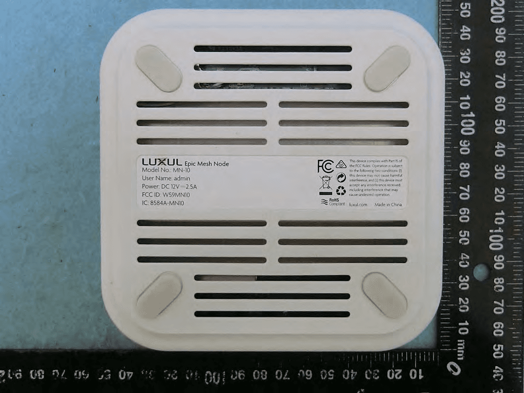
W59MN10
Mar 05, 2020Epic Mesh Node
Equipment Class
DSS - Part 15 Spread Spectrum Transmitter
W59XAP1510
Sep 24, 2015High Power AC1900 Dual-Band Wireless AP
Equipment Class
NII - Unlicensed National Information Infrastructure TX
W59XAP1240
Aug 20, 2015High Power Wireless 300N Outdoor AP
Equipment Class
DTS - Digital Transmission System