W8F800920910WIRELESS PROGRAMMER
Orpak Systems Ltd.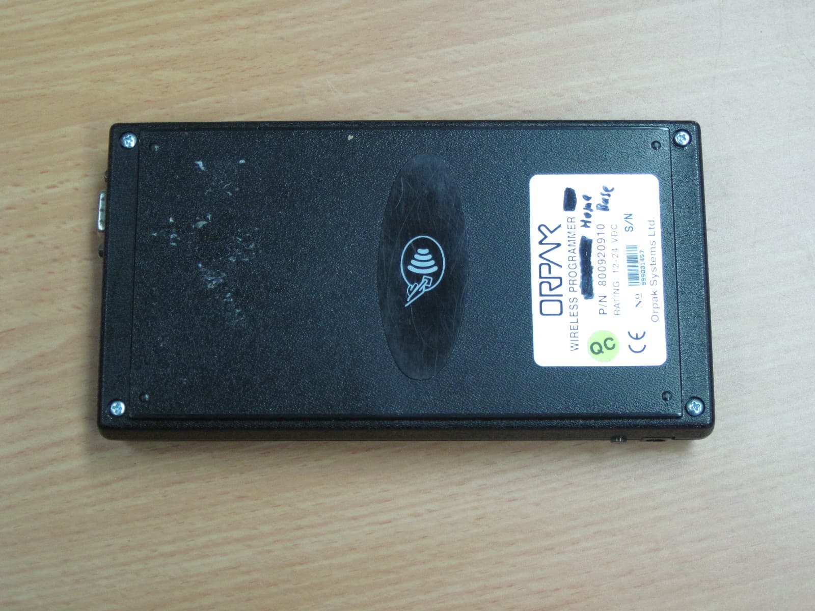
Click to zoom
Application Details
- Equipment Class
- DCD - Part 15 Low Power Transmitter Below 1705 kHz
- Date of Grant
- Jan 19, 2011
- Application Purpose
- Original Equipment
- Date of Application
- Jan 18, 2011
- Equipment Note
- WIRELESS PROGRAMMER
- Frequency Range
- 0.12500000 - 0.12500000
- Company
- Orpak Systems Ltd.
- Country
- Israel
Documents & Files
Document Text
Text extracted from the exhibit documents filed with the FCC. Open a document above to read the original.
Users Manual
Wireless Programmer (WP) – Quick Reference Cat No. 817420910, Ver A1 Wireless Programmer (WP) – Quick Reference 1.1. General The Wireless Programmer (WP) is a portable device (see Figure 1). There are two WP types: Wireless Programmer Home-Base, Cat No. 800920910 Wireless Programmer Retail, Cat No. 800920930 It is a device manufactured for on-the-spot vehicle units issuing for RFID based fueling. The home base version can also configure station equipment such as the Nozzle Reader (NR). An authorized installer can install and program the FuelOpass/ DP/μDP/NR on the customer’s premises using this wireless, programmer (see Figure 1, Figure 2). The WP is used for Programming the following vehicles units: FuelOpass DataPass / μDataPass And for: Programming NR (only for 800920910) Downloading data via RS232 (only for 800920910) Downloading data via GPRS (only for 800920930) WARNING ! Programming using the WP should be done in safe area (Non-Hazardous location). Therefore, it should be done prior to Fuel ring installation! 2 Wireless Programmer (WP) – Quick Reference Cat No. 817420910, Ver A1 2 Figure 1. Wireless Programmer – General View Fixed programming stations Portable Wireless Programming Terminal Centralized Programming Server Security Access Server protected at Orpak premises FuelOpass G P R S n e t w o r k V P N s e c u r e d c h a n n e l DataPass FP Fixed programming stations Portable Wireless Programming Terminal Centralized Programming Server Security Access Server protected at Orpak premises FuelOpass G P R S n e t w o r k V P N s e c u r e d c h a n n e l DataPass FP Figure 2. Programming System in Retail Wireless Programmer (WP) – Quick Reference Cat No. 817420910, Ver A1 1.2. WP SPECIFICATIONS Communication Interfaces: 1. RF communication method Single IEEE802.15.4 wireless channel: Frequency: 2.405-2.485 GHz Wireless Antenna: Built in PCB Antenna Typical Range: 50 meter at open space 2. RFID Reader method with Fuel Ring: Frequency: 125 kHz Two loop (coil) antenna diameters available Reading distance: Up to 8cm 3. Modem GPRS (only for p/n 800920930) 4. RS232 Supply Voltage 7.2V, 2000mAh Lithium Ion internal Battery (Battery pack made of two CGR18650C Panasonic batteries) Battery Charging current 550mA@12VDC Battery Charging Voltage 12V to 28V DC input Charging Temperature Batteries should be charged at temperatures between 10°C and 45°C 1.3. Charging the WP Battery Pack CAUTION ! Don't switch on or operate your Wireless Programmer while its battery is charging! Charging the WP battery takes 8 hours (fully charged); this is done by connecting the batteries charger to the mains and observing the WP Charging LEDs on the WP right hand side: 1. Upon connecting the charger, the LED lights red 2. When the battery is almost full, it turns weak red and the second LED lights green 3. At this stage the batteries continue charging for additional three hours. 4. After three hours the red LED turns Off and only the second LED lights green (end of charging) 3 Wireless Programmer (WP) – Quick Reference Cat No. 817420910, Ver A1 3 1.4. Disposing the Battery Properly dispose a used battery in full compliance with the manufacturer's hazardous waste rules! Do and don't do: Don't toss, drop, or abuse the battery. Don't short-circuit the battery. Don't open and expose the cell contents. Don't modify the battery casing and/or housing Don't expose it to rain or excessive moisture. Don't dispose of batteries in a fire This device complies with Part 15 of the FCC Rules. Operation is subject to the following two conditions: (1) This device may not cause harmful interference and: (2) This device must accept any interference received, including interference that may cause undesired operation THE FCC WANTS YOU TO KNOW: This equipment has been tested and found to comply with the limits or a Class A digital device, pursuant to part 15 of the FCC Rules. These limits are designed to provide reasonable protection against harmful interference when the equipment is operated in a commercial environment. This equipment generates, uses, and can radiate radio frequency energy and, if not installed and used in accordance with the instruction manual, may cause harmful interference to radio communications. Operation of this equipment in a residential area is likely to cause harmful interference in which case the user will be required to correct the interference at his own expense. FCC Warning Modifications not expressly approved by the manufacturer responsible could void the user’s authorit y to operate the equipment under FCC rules.
Cover Letter(s)
REPLACE WITH OFFICIAL COMPANY LOGO / LETTERHEAD Date: 15.12. 2010 Federal Communications Commission Authorization and Evaluation Division Confidentiality Request regarding application for certification of FCC ID: W8F800920910 Pursuant to Sections 0.457 and 0.459 of the Commission’s Rules, we hereby request confidential treatment of information accompanying this application as outlined below: CONF APPENDIX Wireless Programmer BlkDia.pdf CONF APPENDIX Wireless Programmer PartsLst.pdf CONF APPENDIX Wireless Programmer Schem.pdf The above materials contain trade secrets and proprietary information not customarily released to the public. The public disclosure of these materials may be harmful to the applicant and provide unjustified benefits to its competitors. The applicant understands that pursuant to Section 0.457 of the Rules, disclosure of this application and all accompanying documentation will not be made before the date of the Grant for this application. Sincerely, Thank you, Signature: ______________ Printed Name: Gidi Segal Quality Assurance Director Orpak Systems Ltd.
Cover Letter(s)
REPLACE WITH OFFICIAL COMPANY LOGO / LETTERHEAD Date: 15.12.2010 To Whom It May Concern We hereby authorize I.T.L. (Product Testing) Ltd (ITL) to act on our behalf regarding the FCC ID Certification Process for the following application: FCC ID: W8F800920910 Thank you, Signature: ______________ Printed Name: Gidi Segal Quality Assurance Director Orpak Systems Ltd.
Operational Description
Date: 21-12-2010 Operation Description The Orpak Wireless Programmer Home-Base (WP) is a wireless handheld programmer within plastic enclosure (see fig. 1). WP is constructed as combination of a battery operated terminal with keyboard, display and RS232 communication port and two wireless Transmitters. The WP use as installation tool by Trained Installers which downloading vehicle information data from main server via RS232 and programming the FUELOPASS RFID/RFID Cards via 125 KHz Transceiver and programming the Datapass/uDatapass via 2.4 GHz Transceiver. WP transmitters (125 KHz & 2.4 GHz) do not operate simultaneously This document concerning only types of Wireless Programmer (WP): Figure 1. Wireless Programmer (WP) – General View Page 1 of 2 Page 2 of 2 EUT PERFORMANCE VERIFICATION Mode of Operation: Wireless Programmer operated during the tests in a ready mode. Figure 1- Wireless Programmer's Test Set UP
Parts List/Tune Up Info
Date: 15.12.2010 To Whom It May Concern I hereby declare that there is no tune-up procedure for: FCC ID: W8F800920910 Thank you, Gidi Segal Quality Assurance Director Orpak Systems Ltd. Tel: +972-3-577-6866 Fax: +972-3-579-6310 E-mail: [email protected] Website: www.orpak.com Fueling your business for success 3 Consider the environment - do you really need to print this email? CONFIDENTIAL!
RF Exposure Info
1. R.F Exposure/Safety for Wireless Transmitter HomeBase The E.U.T. is used to program FUELOPASS RFID cards and Datapass/μDataPass units. The E.U.T. is handheld. The typical distance between the E.U.T. antennas and the user’s hand in the worst case application, is 2.5cm . Calculation of Maximum Permissible Exposure (MPE) Based on Section 1.1307(b)(1) Requirements 2 1 cm mW (a) FCC limits at MHz is: Using table 1 of Section 1.1310 limit for general population/uncontrolled exposures, the above level is an average over 30 minutes. (b) The power density produced by the E.U.T. is 2 4R GP S tt π = 2 cm mW 1 S – Peak power density according to the limit 1 P t - Transmitted Power 9.72 mw (Peak) G T - Antenna Gain, 1 dBi (Included in the power measurement) R- Minimum safety distance from Transmitter (c) Minimum RF safety distance is: : cm S GP R879.0 4 72.9 4 == ×× × = ππ
Test Report
DATE: 18 January 2011 I.T.L. (PRODUCT TESTING) LTD. FCC Radio Test Report for Orpak Systems Ltd. Equipment under test: Wireless Programmer Home Base 800920910 Written by: _____________________________ D. Shidlowsky, Documentation Approved by: _____________________________ A. Sharabi, Test Engineer Approved by: _____________________________ I. Raz, EMC Laboratory Manager This report must not be reproduced, except in full, without the written permission of I.T.L. (Product Testing) Ltd. This report relates only to items tested. Test Report E104061.01 Orpak Systems Ltd. Page 1 of 67 FCC ACC M Ver 1.1 05Mayl 2000 Test Report E104061.01 Orpak Systems Ltd. Page 2 of 67 FCC ACC M Ver 1.1 05Mayl 2000 Measurement/Technical Report for Orpak Systems Ltd. Wireless Programmer Home Base 800920910 FCC ID: W8F800920910 This report concerns: Original Grant: X Class I Change: Class II Change: Equipment type: Digital Transmission System Limits used: 47CFR15 Section 15.209; 15.247 Measurement procedure used is ANSI C63.4-2003. Application for Certification Applicant for this device: prepared by: (different from "prepared by") Ishaishou Raz Gideon Segal ITL (Product Testing) Ltd. Orpak Systems Ltd. Kfar Bin Nun 31 Lechi St. D.N. Shimshon 99780 P.O.B. 1461 Israel Bnei-Brak 5114 e-mail [email protected] Israel Tel: +972- 3 - 577 - 6868 Fax: +972- 6 - 579 - 6310 e-mail: gidi@orpak .com Test Report E104061.01 Orpak Systems Ltd. Page 3 of 67 FCC ACC M Ver 1.1 05Mayl 2000 TABLE OF CONTENTS 1. GENERAL INFORMATION ------------------------------------------------------------------------------- 5 1.1 Administrative Information ................................................................................. 5 1.2 List of Accreditations ......................................................................................... 6 1.3 Product Description ........................................................................................... 7 1.4 Test Methodology .............................................................................................. 7 1.5 Test Facility ....................................................................................................... 7 1.6 Measurement Uncertainty ................................................................................. 7 2. SYSTEM TEST CONFIGURATION --------------------------------------------------------------------- 8 2.1 Justification ........................................................................................................ 8 2.2 EUT Exercise Software ..................................................................................... 8 2.3 Special Accessories .......................................................................................... 8 2.4 Equipment Modifications ................................................................................... 8 2.5 Configuration of Tested System ........................................................................ 8 3. 6DB MINIMUM BANDWIDTH ---------------------------------------------------------------------------- 9 3.1 Test Specification ............................................................................................ 11 3.2 Test procedure ................................................................................................ 11 3.3 Test Results .................................................................................................... 13 3.4 Test Equipment Used. ..................................................................................... 14 4. RADIATED POWER OUTPUT --------------------------------------------------------------------------15 4.1 Test Specification ............................................................................................ 15 4.2 Test procedure ................................................................................................ 15 4.3 Results............................................................................................................. 17 4.4 Test Equipment Used. ..................................................................................... 18 5. BAND EDGE ------------------------------------------------------------------------------------------------19 5.1 Test procedure ................................................................................................ 19 5.2 Results table .................................................................................................... 20 5.3 Test Equipment Used. ..................................................................................... 21 6. RADIATED EMISSION, 9 KHZ – 30 MHZ -----------------------------------------------------------22 6.1 Test Specification ............................................................................................ 22 6.2 Test Procedure ................................................................................................ 22 6.3 Measured Data ................................................................................................ 22 6.4 Test Instrumentation Used, Radiated Measurements .................................... 23 6.5 Field Strength Calculation ............................................................................... 23 7. SPURIOUS RADIATED EMISSION 30 – 25000 MHZ --------------------------------------------24 7.1 Test Specification ............................................................................................ 24 7.2 Test Procedure ................................................................................................ 24 7.3 Test Data ......................................................................................................... 25 7.4 Test Instrumentation Used, Radiated Measurements .................................... 28 7.5 Field Strength Calculation 30 – 1000 MHz ..................................................... 29 8. RADIATED POWER SPECTRAL DENSITY --------------------------------------------------------3…
Text truncated - open the document above for the full version.
Contact Information
Applicant
Yair Elul(Quality Assurance Director)
Test Firm
Israel Testing LaboratoriesIIan Cohen
Technical Specifications
| # | Rule Parts | Frequency Range | Power Output |
|---|---|---|---|
| 1 | 15C | 0.125 MHz - 0.125 MHz | - |
Other Applications from Orpak Systems Ltd.
W8F819527450
Aug 13, 2020nWGT-W Outdoor unit w/p.s., nWGT-W Outdoor unit w/o p.s, nWGT-W (Pump, SAMx1, LAN)
Equipment Class
DTS - Digital Transmission System
W8F800927160
Feb 26, 2020Tag Reader TR500
Equipment Class
DCD - Part 15 Low Power Transmitter Below 1705 kHz
W8F800960000
Dec 22, 2014Fuel Pump Nozzle Reader NNR + Switch
Equipment Class
DCD - Part 15 Low Power Transmitter Below 1705 kHz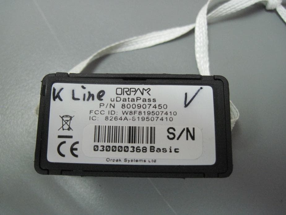
W8F819507450
Aug 04, 2014uDataPass
Equipment Class
DTS - Digital Transmission System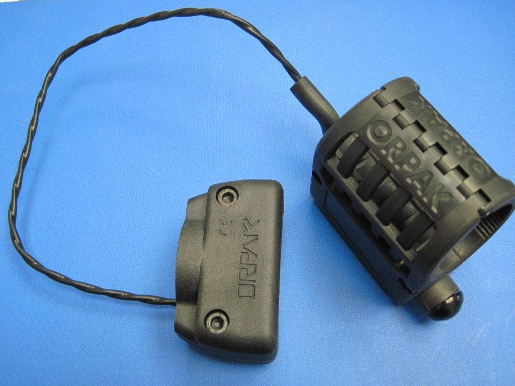
W8F800942XXX
Jul 08, 2013NOZZLE READER UNR
Equipment Class
DCD - Part 15 Low Power Transmitter Below 1705 kHz