W8F800960000Fuel Pump Nozzle Reader NNR + Switch
Orpak Systems Ltd.
Click to zoom
Application Details
- Equipment Class
- DCD - Part 15 Low Power Transmitter Below 1705 kHz
- Date of Grant
- Dec 22, 2014
- Application Purpose
- Original Equipment
- Date of Application
- Dec 22, 2014
- Equipment Note
- Fuel Pump Nozzle Reader NNR + Switch
- Frequency Range
- 0.12500000 - 0.12500000
- Company
- Orpak Systems Ltd.
- Country
- Israel
Documents & Files
Document Text
Text extracted from the exhibit documents filed with the FCC. Open a document above to read the original.
Users Manual
Parameter Value Supply Voltage 3.6 internal battery pack P/N 812560010 Power Consumption Active Mode: 160mA Standby Mode 20 μA Operating Temperature -40° to +60° C Storage Temperature -40° to +85° C IP Rating IP 67 Dimensions (HxWxD) 41x84x60.5mm Weight 132gCommunication Interface RF to WGT: 2.405-2.480GHz Typical transmission power: 3dbm (2mW) RFID to FuelOpass: 108-131 kHz Zone 1 Explosive atm ospher e ( Ex) ia ( intr insic safety) pr otection level Gr oup IIC type pr oduct TemperatureClass:T6 Rated Tem per atur es:- 40°< Tam b< + 60° C Specifications The FCC Wants You to Know:This equipment has been tested and found to comply with the limits for a Class A & B digital device, pursuant to Part 15 of the FCC rules. These limits are designed to provide reasonable protection against harmful interference in a residential installation. This equipment generates uses and can radiate radio frequency energy and, if not installed and used in accordance with the instructions, may cause harmful interference to radio communications. However, there is no guarantee that interference will not occur in a particular installation. If this equipment does cause harmful interference to radio or television reception, which can be determined by turning the equipment off and on, the user is encouraged to try to correct the interference by one or more of the following measures :a) Reorient or relocate the receiving antenna.b) Increase the separation between the equipment and receiver.c) Connect the equipment to an outlet on a circuit different from that to which the receiver is connected.d) Consult the dealer or an experienced radio/TV technician. Changes or modifications to this unit not expressly approved by the party responsible for compliance could void the user’s authority to operate the equipment. This device complies with FCC Rules Part 15 and with Industry Canada licence-exempt RSS standard(s). Operation is subject to two conditions: (1) This device may not cause harmful interference, and (2) this device must accept any interference that may be received or that may cause undesired operation. Le present appareil est conforme aux CNR d'Industrie Canada applicables aux appareils radio exempts de licence. L'exploitation est autorisee aux deux conditions suivantes :(1) l'appareil ne doit pas produire de brouillage, et (2) l'utilisateur de l'appareil doit accepter tout brouillage radioelectrique subi, meme si le brouillage est susceptible d'en compromettre le fonctionnement. FCC Compliance Statement Warning Universal KitnNR universal kit suits any spout diameter between 22mm and 32mm as it includes 4 grip kits. Choose your grip kit according to the table below: Husky 1A 30 6 Husky X 27 6 OPW 11 A/B Leaded 30 6 OPW 11 A/B Unleaded 27 6 OPW Avance HS/VR 32 6 OPW DEF 27 6 Tatsuno Leaded 30 6 Tatsuno Unleaded 27 6 ZVA 25 32 6 ZVA DEF 24 8 ZVA Slim Line 30 6 ZVA S.L. 2-GR 30 6 Nozzle Model Grip Kit** Set Screws* *Use 10mm set screws when spout diameter is 22mm or below. ** The 32mm grip kit includes only a two-pieces top lid instead of two lids. FOR SUCCESS FUELING YOUR BUSINESS nano Nozzle Reader Assembly Guide Hazardous Area Watch nNR Installation Tutorial P/N 817460005 Slide the adaptor over the spout. Place it as close as possible to thenozzle bodyChoose the proper grip kit for the nozzle (see rear table). Place a lid, the rubber fillerand then the other lid Secure the gip kit with the M4 screws. Tighten them in stages and in a diagonal sequence. Use a 3mm head ratchet Apply glue and place the set screws in the adaptor corners. Use a 2mm Allen key Slide the nNR assembly over the spout Secure the nNR to the adaptor with the M3screws. Use a 2mm Allen key Place the nNR front cover on top of the assembly. Secure with the M3 screws. Use a 2mm Allen key Installation Kit 1 2 3 4 5 6 7 8 9 1 Set Screws 815221300 (6) 815221380 (8) 815221310 (10) 2 Spout Adaptor 814360500 3 Lids 814360424 (24) 814160427 (27) 814160430 (30) 814360700 (32) 4 Rubber Filler 814160024 (24) 814160027 (27) 814160030 (30) 814160032 (32) 5 M4 Screws 815213424 6 nNR Assembly 819260000 (nNR)/819260100(nNR + Switch) 7 M3 Screws 815260300 8 Front Cover 814360200 9 M3x6 Screws 815260200 # Part Name Part Number 3 Required Tools 2mm standard Allen key (not ball ended) 3mm Allen head ratchet (not ball ended) Loctite 222/Holdtite T43 glue Unit should be serviced only by authorized service personnel. Program the unit Opening of the unit by Service Personnelmust not be done at the location of installation. When replacing the battery, use only P/N 812560010. Installation Notes 12 34 56 78 3mm 2mm 2mm 2mm 412141412 Qty.
Cover Letter(s)
Date: 28 August 2014 To: Timco Engineering Inc. To Whom It May Concern We hereby authorize Mr. Shaike Raz of I.T.L. (Product Testing) Ltd (ITL) to sign FORM 731 on our behalf for the following application: FCC ID: W8F800960000 Thank you, Gidi Segal Quality Assurance Director Orpak Systems Ltd. Tel: +972-3-577-6866 Fax: +972-3-579-6310 E-mail: [email protected] Website: www.orpak.com Fueling your business for success Consider the environment - do you really need to print this email? CONFIDENTIAL!
Cover Letter(s)
REPLACE WITH OFFICIAL COMPANY LOGO / LETTERHEAD Date: 28 August 2014 attn: Reviewing Engineer Federal Communications Commission 7435 Oakland Mills Road Columbia, MD 21046 To Whom It May Concern: The NNR + Switch, FCC ID: W8F800960000 and label is so small that it cannot include the statement specified in FCC Part 15 Sub-part A, Section 15.19 (a) (3) “This device complies with Part 15 of the FCC Rules. Operation is subject to the following two conditions: (1) This device may not cause harmful interference and (2) This device must accept any interference received, including interference that may cause undesired operation." Due to this reason, we are using the provisions of Part 15 Sub-part A, Section 15.19 (a) (5) and this statement appears in a prominent location in the user manual. Please contact me if there is any information you may need. Thank you, Signature: ______________ Printed Name: Gidi Segal Quality Assurance Director Orpak Systems Ltd.
Cover Letter(s)
REPLACE WITH OFFICIAL COMPANY LOGO / LETTERHEAD Date: 28 August 2014 To Whom It May Concern We hereby authorize I.T.L. (Product Testing) Ltd (ITL) to act on our behalf regarding the FCC ID Certification Process for the following application: FCC ID: W8F800960000 Thank you, Signature: ______________ Printed Name: Gidi Segal Quality Assurance Director Orpak Systems Ltd.
Cover Letter(s)
REPLACE WITH OFFICIAL COMPANY LOGO / LETTERHEAD Date: 2 December 2014 Federal Communications Commission Authorization and Evaluation Division Confidentiality Request regarding application for certification of FCC ID: W8F800960000 Pursuant to Sections 0.457 and 0.459 of the Commission’s Rules, we hereby request confidential treatment of information accompanying this application as outlined below: CONF APPENDIX NNR + Switch BlkDia.pdf CONF APPENDIX NNR + Switch PartsLst.pdf CONF APPENDIX NNR + Switch Schem.pdf CONF APPENDIX NNR + Switch OpDes.pdf CONF APPENDIX NNR + Switch IntPho.pdf The above materials contain trade secrets and proprietary information not customarily released to the public. The public disclosure of these materials may be harmful to the applicant and provide unjustified benefits to its competitors. The exceptional circumstance allowing long term confidentiality for interior photos for this application are: The product NNR is a component which is used in a payment application for reading and transferring credit card data which is Security Information. The Internal Photos contain trade and secrets and proprietary information not customarily to public. The public disclosure of these materials may be harmful to the applicant and provide unjustified benefits to its competitors. The NNR pcb which contains both the 2.4 GHz and 125kHz transmitters is covered in epoxy (ENCAPSULATED). Removal of the epoxy will cause damage to the circuit boards and the transmitters will cease to function. The applicant understands that pursuant to Section 0.457 of the Rules, disclosure of this application and all accompanying documentation will not be made before the date of the Grant for this application. Sincerely, Thank you, Signature: ______________ Printed Name: Gidi Segal Quality Assurance Director Orpak Systems Ltd.
External Photos
NNR Large NNR NNR + Switch NNR NNR Large NNR Large + Switch
Parts List/Tune Up Info
Date: 28 August 2014 To Whom It May Concern I hereby declare that there is no tune-up procedure for: FCC ID: W8F800960000 Thank you, Gidi Segal Quality Assurance Director Orpak Systems Ltd. Tel: +972-3-577-6866 Fax: +972-3-579-6310 E-mail: [email protected] Website: www.orpak.com Fueling your business for success Consider the environment - do you really need to print this email? CONFIDENTIAL!
Test Report
Test Report E135942.02Orpak SystemsLtd.Page1of73 FCC ACC M Ver1.105Mayl 2000 DATE:27August2014 I.T.L. (PRODUCT TESTING) LTD. FCC Radio Test Report for Orpak Systems Ltd. Equipment under test: Fuel Pump Nozzle Reader NNR*; NNR + SWITCH; NNR LARGE; NNR LARGE + SWITCH *See customer’s Declaration on page6 Written by:_____________________________ R.Pinchuck,Documentation Approved by:_____________________________ M. Zohar,Test Engineer Approved by:_____________________________ I. Raz, EMC Laboratory Manager This report must not be reproduced, except in full, without the written permission of I.T.L. (ProductTesting) Ltd. This report relates only to items tested. Test Report E135942.02Orpak SystemsLtd.Page2of73 FCC ACC M Ver 1.105Mayl 2000 Measurement/Technical Report for Orpak Systems Ltd. Fuel Pump Nozzle Reader NNR*; NNR + SWITCH; NNR LARGE; NNR LARGE + SWITCH *Seecustomer’s Declaration on page6 FCC ID:W8F800960000 IC:8264A-800960000 This report concerns:Original Grant:X Class I Change: Class IIChange: Equipment type:Spread Spectrum/Digital Device 2400-2483.5 MHz and Part 15 Low Power Transmitter Below 1705 kHz Limits used:47CFR15 Section15.209,47CFR15 Section15.247 Measurement procedure used isKDB 558074 D01v03r02 June 5, 2014and ANSI C63.4: 2003. Application for CertificationApplicant for this device: prepared by:(different from "prepared by") R. PinchuckGideonSegal ITL (Product Testing) Ltd.Orpak Systems Ltd. 1 Bat Sheva Street31Lechi St. Lod, 7116002P.O.B. 1461 IsraelBnei-Brak,51114 [email protected] Tel:+972-3-577-6868 Fax:+972-3-579-6310 e-mail: [email protected] Test Report E135942.02Orpak SystemsLtd.Page3of73 FCC ACC M Ver 1.105Mayl 2000 TABLE OF CONTENTS 1.GENERAL INFORMATION-------------------------------------------------------------------------------5 1.1Administrative Information.................................................................................5 1.2List of Accreditations.........................................................................................7 1.3Product Description...........................................................................................8 1.4Test Methodology..............................................................................................8 1.5Test Facility.......................................................................................................8 1.6Measurement Uncertainty.................................................................................8 2.SYSTEM TEST CONFIGURATION---------------------------------------------------------------------9 2.1Justification........................................................................................................9 2.2EUT Exercise Software.....................................................................................9 2.3Special Accessories..........................................................................................9 2.4Equipment Modifications...................................................................................9 2.5Configuration of Tested System........................................................................9 3.TEST SETUP PHOTOS-----------------------------------------------------------------------------------10 4.FIELD STRENGTH OF FUNDAMENTAL (125 KHZ TRANSMITTER)-----------------------12 4.1Test Specification............................................................................................12 4.2Test Procedure................................................................................................12 4.3Test Results for NNR + SWITCH....................................................................13 4.4Test Results for NNR LARGE and NNR LARGE + SWITCH..........................16 4.4Test Instrumentation Used; Field Strength of Fundamental............................21 5.RADIATED EMISSION, 9KHZ–30 MHZ (125 KHZ TRANSMITTER)-----------------------22 5.1Test Specification............................................................................................22 5.2Test Procedure................................................................................................22 5.3Test Results for NNR + SWITCH....................................................................22 5.4Test Results for NNR LARGE and NNR LARGE + SWITCH..........................24 5.5Test Instrumentation Used; Radiated Measurements.....................................27 5.6Field Strength Calculation...............................................................................28 6.BANDWIDTH FOR 125 KHZ TRANSMITTER------------------------------------------------------29 6.1Test Specification............................................................................................29 6.2Test procedure................................................................................................29 6.3Test Results.....................................................................................................29 6.4Test Equipment Used; Bandwidth...................................................................32 7.6DB MINIMUM BANDWIDTH---------------------------------------------------------------------------33 7.1Test Specification............................................................................................33 7.2Test procedure................................................................................................33 7.3Test Results.....................................................................................................33 7.4Test Equipment Used, 6dB Minimum Bandwidth............................................36 8.26DB MINIMUM BANDWIDTH-------------------------------------------------------------------------37 8.1Test Specification............................................................................................37 8.2Test procedure................................................................................................37 8.3Test Results........................…
Text truncated - open the document above for the full version.
Test Setup Photos
Test Setup Photos
Contact Information
Applicant
Yair Elul(Quality Assurance Director)
Test Firm
Israel Testing LaboratoriesIIan Cohen
Technical Specifications
| # | Rule Parts | Frequency Range | Power Output |
|---|---|---|---|
| 1 | 15C | 0.125 MHz - 0.125 MHz | - |
Other Applications from Orpak Systems Ltd.
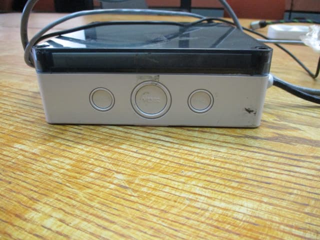
W8F819527450
Aug 13, 2020nWGT-W Outdoor unit w/p.s., nWGT-W Outdoor unit w/o p.s, nWGT-W (Pump, SAMx1, LAN)
Equipment Class
DTS - Digital Transmission System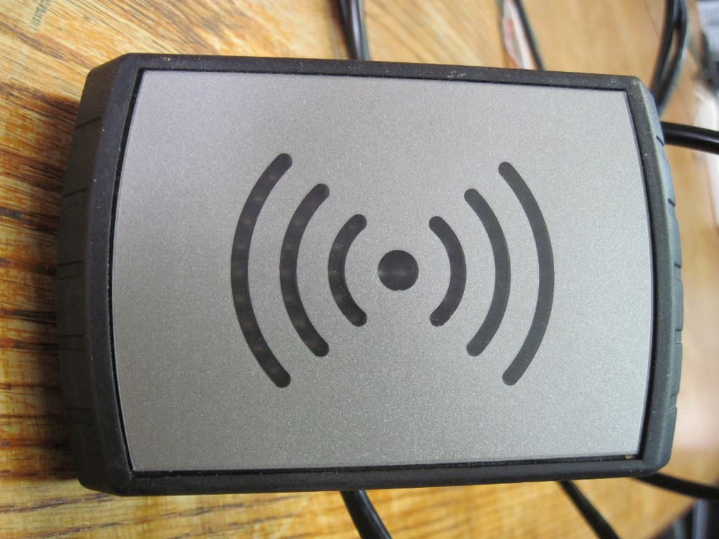
W8F800927160
Feb 26, 2020Tag Reader TR500
Equipment Class
DCD - Part 15 Low Power Transmitter Below 1705 kHz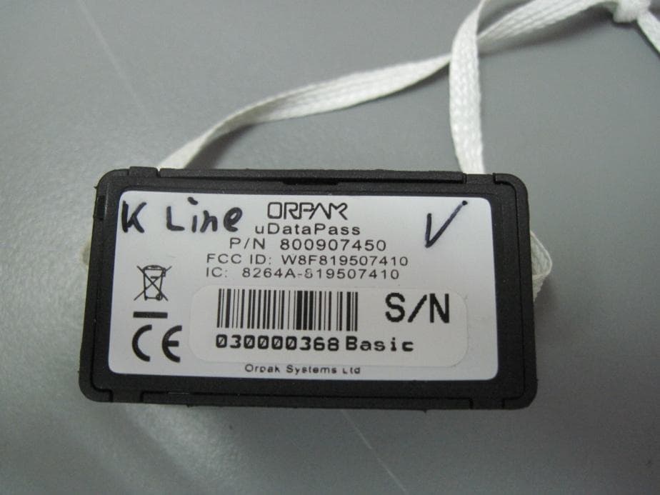
W8F819507450
Aug 04, 2014uDataPass
Equipment Class
DTS - Digital Transmission System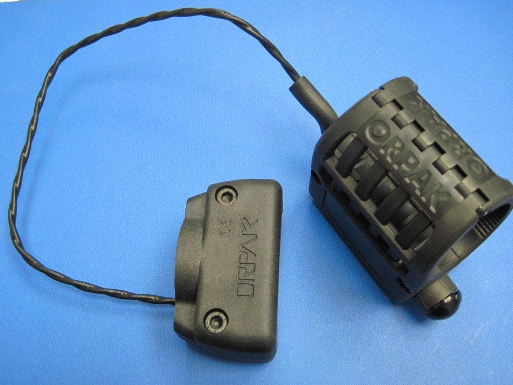
W8F800942XXX
Jul 08, 2013NOZZLE READER UNR
Equipment Class
DCD - Part 15 Low Power Transmitter Below 1705 kHz
W8F813207300
Oct 14, 2012DATAPASS
Equipment Class
DTS - Digital Transmission System