W8F800927160Tag Reader TR500
Orpak Systems Ltd.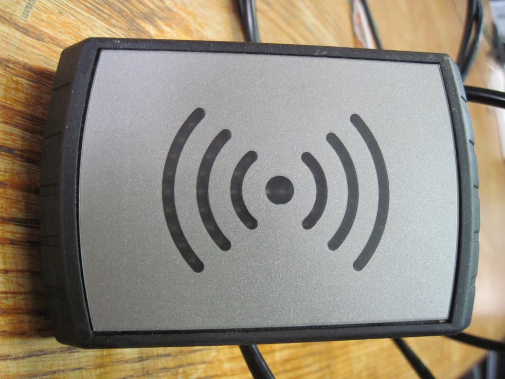
Click to zoom
Application Details
- Equipment Class
- DCD - Part 15 Low Power Transmitter Below 1705 kHz
- Date of Grant
- Feb 26, 2020
- Application Purpose
- Original Equipment
- Date of Application
- Feb 26, 2020
- Equipment Note
- Tag Reader TR500
- Frequency Range
- 0.12500000 - 0.12500000
- Company
- Orpak Systems Ltd.
- Country
- Israel
Documents & Files
Document Text
Text extracted from the exhibit documents filed with the FCC. Open a document above to read the original.
Users Manual
P/N: 817427160 Revision A3 ForePay Installation Manual TERMS AND CONDITIONS All products and services provided by Orpak Systems Ltd. without exception are subject to the Orpak Systems Ltd. General Terms and Conditions. Ensure that you read through the General Terms and Conditions completely prior to performing any procedures detailed in this document. SAFETY CONSIDERATIONS Carefully read all warnings and instructions, provided to help you install and maintain the equipment safely in the highly flammable environment of a gas station. Disregarding these warnings and instructions could result in serious injury and property loss or damage. It is your responsibility to install, operate and maintain the equipment according to the instructions in this manual, and to conform to all applicable codes, regulations and safety measures. Failure to do so could void all warranties associated with this equipment. Ensure that the installation is performed by experienced personnel, licensed to perform work in gas stations and in flammable environments, according to the local regulations and all relevant standards. WARNING -EXPLOSION HAZARD Use a separate conduit for intrinsically safe wiring. Do not run any other wires or cables through this conduit, since it may lead to an explosion hazard. Use standard test equipment only in the non- hazardous area of the fuel station, and approved test equipment for the hazardous areas. Installation and service must comply with all applicable requirements of the National Fire Protection Association NFPA-30 “Flammable and Combustible Liquids Code”, NFPA-30A “Automotive and Marine Service Station Code”, NFPA-70 “National Electric Code”, federal, state and local codes and any other applicable safety codes and regulations. Do not perform metal work in a hazardous area. Sparks generated by drilling, tapping and other metal work operations could ignite fuel vapors and flammable liquids, resulting in death, serious personal injury, property loss and damage to you and other persons. CAUTION -SHOCK HAZARD Dangerous AC voltages that could cause death or serious personal injury are used to power the equipment. Always disconnect power before working on the equipment. The equipment may have more than one power supply connection point. Disconnect all power before servicing. WARNING – PASSING VEHICLES When working in an open area, block off the work area to protect yourself and other persons. Use safety cones or other signaling devices. WARNING Substitutions of components could impair intrinsic safety. Use of unauthorized components or equipment will void all warranties associated with this equipment. TR500 InstallationandSetupManualIII CAUTION Do not attempt to make any repair on the printed circuit boards that reside in the equipment, as this will void all warranties associated with this equipment. PROPRIETARY NOTICE The information contained in this guide is confidential and proprietary to Orpak Systems Ltd. No part of this guide may be disclosed or reproduced in any form without written permission of Orpak Systems Ltd. The information provided in this document is current as of the date of its publication,and it may be changed at any time without notice. DISCLAIMER This document is provided for reference only and while every effort has been made to ensure correctness at the time of publication, Orpak Systems Ltd. assumes no responsibility for errors or omissions. FCC COMPLIANCE STATEMENT This equipment has been tested and found to comply with the limits for a Class B & C digital device, pursuant to Part 15 of the FCC rules. These limits are designed to provide reasonable protection against harmful interference in a residential installation. This equipment generates, uses and can radiate radio frequency energy and, if not installed and used in accordance with the instructions, may cause harmful interference to radio communications. However, there is no guarantee that interference will not occur in a particular installation. If this equipment does cause harmful interference to radio or television reception, which can be determined by turning the equipment off and on, the user is encouraged to try to correct the interference by one or more of the following measures: Reorient or relocate the receiving antenna Increase the separation between the equipment and receiver Connect the equipment to an outlet on a circuit different from that to which the receive is connected Consult an authorized dealer or service representative for help FCC WARNING Modifications not expressly approved by the manufacturer could void the user authority to operate the equipment under FCC Rules. This document is the property of: Orpak Systems Ltd. Israel IVTR500 InstallationandSetupManual TableofContents Section 1 Introduction 1.1. General8 1.2. SolutionDescription8 1.3. DocumentationConventions8 Section 2 System Overview 2.1. General9 2.2. Specifications9 2.2.1. GeneralSpecifications9 2.3. Layout & Dimensions10 2.4. Product Label11 Section 3 Preliminary Guidelines 3.1. General15 3.2. PrecautionsandSafety Information15 3.3. Preliminary Considerations17 3.4. RequiredTools19 Section 4 Installation 4.1. General21 4.2. InstallationProcedures21 4.2.1. InstallationonDoor/Front of Pump21 4.2.2. InstallationwithBracket onTopof Pump22 4.2.3. InstallationwithBracket onTopof Pump23 TR500 InstallationandSetupManualV ListofFigures Figure 2-1 - TR500 Layout & Dimensions11 Figure 2-2 - TR500 Product Label Location12 Figure 2-3 - TR500 Product Label13 Figure 3-1 - Dimensions18 Figure 4-1 - Drilling Template21 Figure 4-2 - Mounting Bracket23 VITR500 InstallationandSetupManual ListofTables Table 2-1 - General Specifications10 Table 4-1 - Top/Wall Mounting Kit - P/N 81902719022 Table 4-2 - Top/Wall Mounting Kit - P/N 81902719023 TR500 InstallationandSetupManualVII Section 1 Introduction 1.1. General This manual provides instructions on how to install and configure the TR500, Orpak's flexible and cost- effective outdoor payment and…
Text truncated - open the document above for the full version.
Cover Letter(s)
Tel. +972-3-577-6868 Fax. +972-3-579-6310 __________________ 31 Lechi St. P.O.B 1461 Bnei Brak 5111401 Israel ____________________ ORPAK Systems Ltd. w w w . o r p a k . c o m _________________ Date: December 26, 2019 Federal Communications Commission Authorization and Evaluation Division Confidentiality Request regarding application for certification application of FCC ID: W8F800927160 Pursuant to Sections 0.457 and 0.459 of the Commission’s Rules, we hereby request confidential treatment of information accompanying this application as outlined below: CONF APPENDIX TR500 BlkDia.pdf CONF APPENDIX TR500 Schem.pdf CONF APPENDIX TR500 PartsLst.pdf CONF APPENDIX TR500 OpDes.pdf The above materials contain trade secrets and proprietary information not customarily released to the public. The public disclosure of these materials may be harmful to the applicant and provide unjustified benefits to its competitors. Sincerely, Yair Elul Engineering Manager Orpak Systems LTD.
Cover Letter(s)
Tel. +972-3-577-6868 Fax. +972-3-579-6310 __________________ 31 Lechi St. P.O.B 1461 Bnei Brak 5111401 Israel ____________________ ORPAK Systems Ltd. w w w . o r p a k . c o m _________________ Date: December 26, 2019 To Whom It May Concern We hereby authorize Mr. Ilan Cohen of I.T.L. (Product Testing) Ltd (ITL) to act on our behalf regarding the FCC ID Certification Process for the following application: FCC ID: W8F800927160 Thank you, Yair Elul, Engineering Manager Orpak Systems LTD.
Cover Letter(s)
Tel. +972-3-577-6868 Fax. +972-3-579-6310 __________________ 31 Lechi St. P.O.B 1461 Bnei Brak 5111401 Israel ____________________ ORPAK Systems Ltd. w w w . o r p a k . c o m _________________ Date: December 26, 2019 To: Timco Engineering Inc. To Whom It May Concern We hereby authorize Mr. Ilan Cohen of I.T.L. (Product Testing) Ltd (ITL) to sign FORM 731 on our behalf for the following certification application: FCC ID: W8F800927160 Thank you, Yair Elul Engineering Manager Orpak Systems LTD.
ID Label/Location Info
Label sample Label location
Internal Photos
To LF 125KHz channel: Inside this black frame we have the 125KHz antenna coil. Connect to the PCB with the 2 black wires and connector To HF 13.56MHz channel: These printed lines on the PCB are the HF antenna for the 13.56MHz channel
Parts List/Tune Up Info
Tel. +972-3-577-6868 Fax. +972-3-579-6310 __________________ 31 Lechi St. P.O.B 1461 Bnei Brak 5111401 Israel ____________________ ORPAK Systems Ltd. w w w . o r p a k . c o m _________________ Date: December 26, 2019 To Whom It May Concern I hereby declare that there is no tune-up procedure for: FCC ID: W8F800927160 Thank you, Yair Elul Engineering Manager Orpak Systems LTD.
Test Report
Test Report E202322.00 Orpak Systems Ltd. Page 1 of 31 FCC ACC M Ver 1.1 05Mayl 2000 DATE: 23 December 2019 I.T.L. (PRODUCT TESTING) LTD. FCC/IC Radio Test Report For Orpak Systems Ltd. Equipment under test: Tag Reader TR500 (125kHz transmitter) Tested by: _____________________________ M. Zohar Approved by: _____________________________ D. Shidlowsky This report must not be reproduced, except in full, without the written permission of I.T.L. (Product Testing) Ltd. This report relates only to items tested. Test Report E202322.00 Orpak Systems Ltd. Page 2 of 31 FCC ACC M Ver 1.1 05Mayl 2000 Measurement/Technical Report for Orpak Systems Ltd. Tag Reader TR500 FCC ID: W8F800927160 IC: 8264A-800927160 This report concerns: Original Grant: X Class I Change: Class II Change: Equipment type: FCC: DCD - Part 15 Low Power Transmitter Below 1705 kHz IC: Low Power Transmitter General Field Limits (9kHz-30MHz) Limits used: 47CFR15 Section 15.209 RSS-Gen, Issue 5, November 2018 Measurement procedure used ANSI C.63.10 2013 Application for Certification Applicant for this device: prepared by: (different from "prepared by") R. Pinchuck Yair Elul ITL (Product Testing) Ltd. Orpak Systems Ltd. 1 Bat Sheva Street 31 Lechi St. Lod, 7120101 P.O.B. 1461 Israel Bnei-Brak, 51114 e-mail [email protected] Israel Tel: +972- 3 - 577 - 6868 Fax: +972- 3 - 579 - 6310 e-mail: [email protected] Test Report E202322.00 Orpak Systems Ltd. Page 3 of 31 FCC ACC M Ver 1.1 05Mayl 2000 TABLE OF CONTENTS 1. GENERAL INFORMATION --------------------------------------------------------------------------- 4 1.1 Administrative Information ........................................................................... 4 1.2 List of Accreditations ................................................................................... 5 1.3 Product Description ..................................................................................... 6 1.4 Test Methodology ........................................................................................ 6 1.5 Test Facility ................................................................................................. 6 1.6 Measurement Uncertainty ........................................................................... 6 2. SYSTEM TEST CONFIGURATION ----------------------------------------------------------------- 7 2.1 Justification .................................................................................................. 7 2.2 EUT Exercise Software ............................................................................... 7 2.3 Special Accessories .................................................................................... 7 2.4 Equipment Modifications ............................................................................. 7 2.5 Configuration of Tested System .................................................................. 8 3. CONDUCTED & RADIATED MEASUREMENT TEST SETUP PHOTOS ---------------- 9 4. CONDUCTED EMISSION FROM AC MAINS -------------------------------------------------- 10 4.1 Test Specification ...................................................................................... 10 4.2 Test Procedure .......................................................................................... 10 4.3 Test Limit ................................................................................................... 10 4.4 Test Results............................................................................................... 11 4.5 Test Equipment Used; Conducted Emission from AC Mains .................... 16 5. FIELD STRENGTH OF FUNDAMENTAL ------------------------------------------------------- 17 5.1 Test Specification ...................................................................................... 17 5.2 Test Procedure .......................................................................................... 17 5.3 FCC Test Limit .......................................................................................... 17 5.4 IC Test Limit .............................................................................................. 18 5.5 Test Results............................................................................................... 18 5.6 Test Instrumentation Used; Field Strength of Fundamental ..................... 20 6. RADIATED EMISSION, 9 KHZ – 30 MHZ ------------------------------------------------------ 21 6.1 Test Specification ...................................................................................... 21 6.2 Test Procedure .......................................................................................... 21 6.3 FCC Test Limit .......................................................................................... 21 6.4 IC Test Limit .............................................................................................. 22 6.5 Test Results............................................................................................... 22 6.6 Test Instrumentation Used; Radiated Emission ........................................ 24 6.7 Field Strength Calculation ......................................................................... 24 7. OCCUPIED BANDWIDTH -------------------------------------------------------------------------- 25 7.1 Test Specification ...................................................................................... 25 7.2 Test Procedure .......................................................................................... 25 7.3 Test Limit ................................................................................................... 25 7.4 Test Results............................................................................................... 25 7.5 Test Equipment Used; Occupied Bandwidth ............................................. 26 8. APPENDIX A - CORRECTION FACTORS ----------------------------------------------------- 27 8.1 Correction factors for…
Text truncated - open the document above for the full version.
Test Setup Photos
Test Set-Up Photos Conducted Emission Test Frequency Stability Field Strength of Fundamental & Radiated Emission Test Setup, 0.009-30MHz Radiated Emission 30MHz-150MHz
Contact Information
Applicant
Yair Elul(Quality Assurance Director)
Test Firm
ITL PRODUCT TESTING LTDIlan Cohen
Technical Specifications
| # | Rule Parts | Frequency Range | Power Output |
|---|---|---|---|
| 1 | 15C | 0.125 MHz - 0.125 MHz | - |
Other Applications from Orpak Systems Ltd.
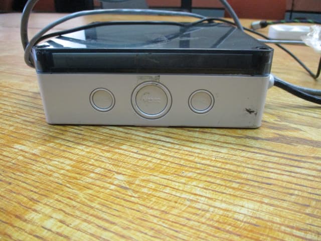
W8F819527450
Aug 13, 2020nWGT-W Outdoor unit w/p.s., nWGT-W Outdoor unit w/o p.s, nWGT-W (Pump, SAMx1, LAN)
Equipment Class
DTS - Digital Transmission System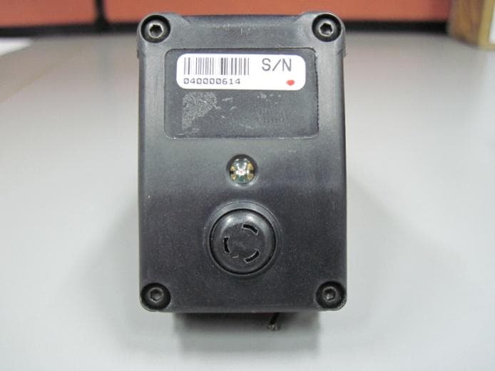
W8F800960000
Dec 22, 2014Fuel Pump Nozzle Reader NNR + Switch
Equipment Class
DCD - Part 15 Low Power Transmitter Below 1705 kHz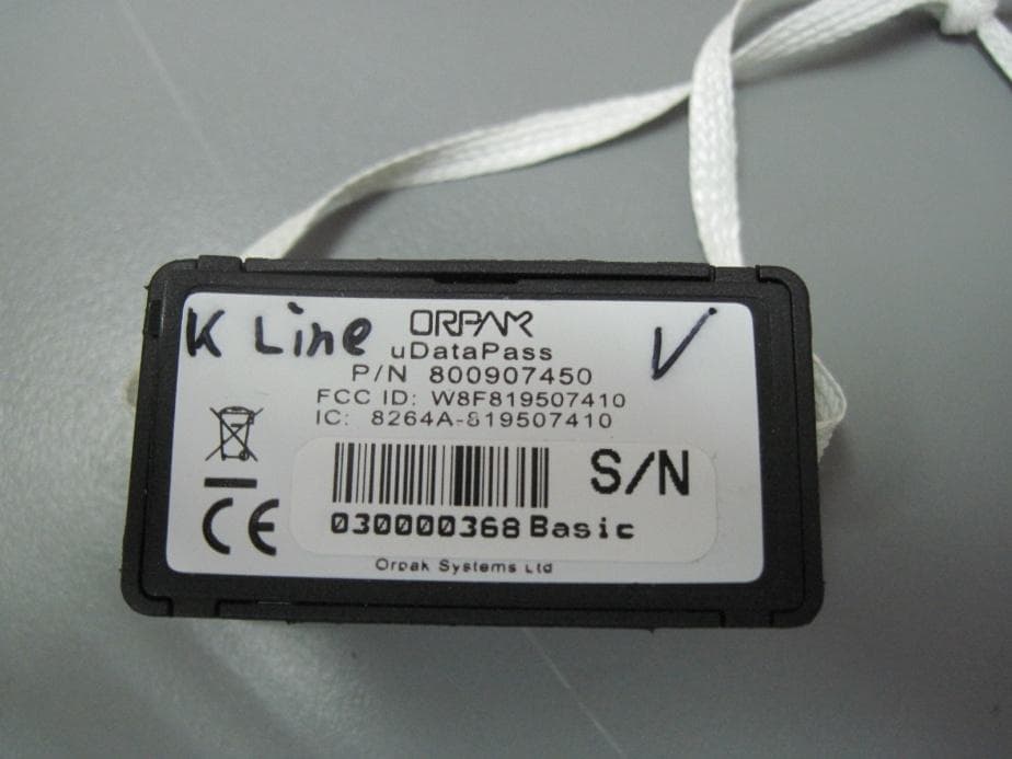
W8F819507450
Aug 04, 2014uDataPass
Equipment Class
DTS - Digital Transmission System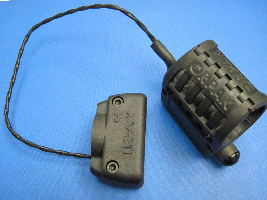
W8F800942XXX
Jul 08, 2013NOZZLE READER UNR
Equipment Class
DCD - Part 15 Low Power Transmitter Below 1705 kHz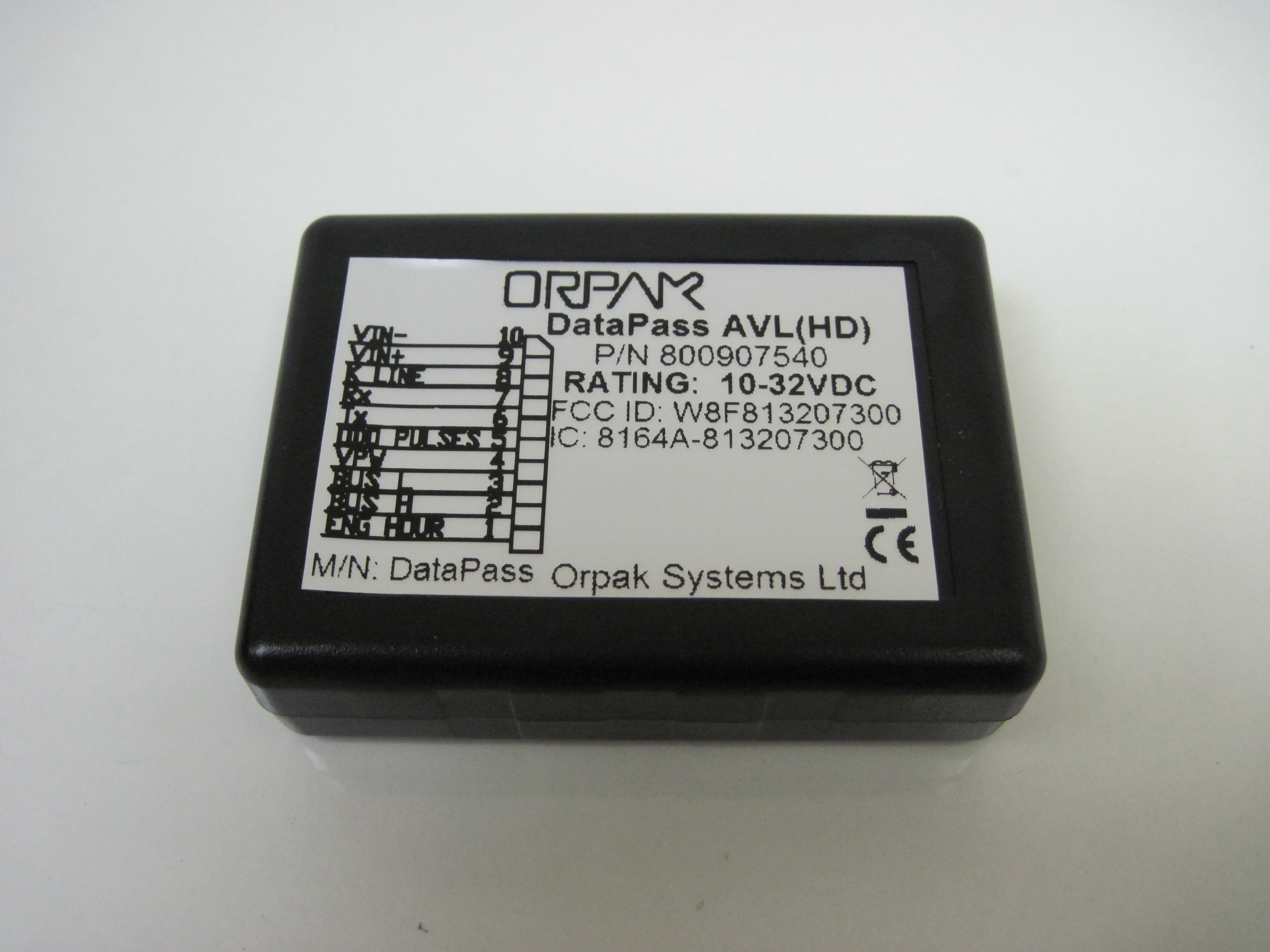
W8F813207300
Oct 14, 2012DATAPASS
Equipment Class
DTS - Digital Transmission System