W8F819507450uDataPass
Orpak Systems Ltd.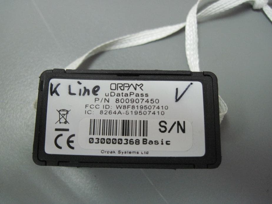
Click to zoom
Application Details
- Equipment Class
- DTS - Digital Transmission System
- Date of Grant
- Aug 04, 2014
- Application Purpose
- Original Equipment
- Date of Application
- Aug 04, 2014
- Equipment Note
- uDataPass
- Frequency Range
- 2405.00000000 - 2480.00000000
- Company
- Orpak Systems Ltd.
- Country
- Israel
Documents & Files
Document Text
Text extracted from the exhibit documents filed with the FCC. Open a document above to read the original.
Users Manual
P/N 817407450 Revision A FuelOmat Gold μDataPass Installation Manual FCC Compliance Statement The FCC Wants You to Know: This equipment has been tested and found to comply with the limits for a Class A & B digital device, pursuant to Part 15 of the FCC rules. These limits are designed to provide reasonable protection against harmful interference in a residential installation. This equipment generates uses and can radiate radio frequency energy and, if not installed and used in accordance with the instructions, may cause harmful interference to radio communications. However, there is no guarantee that interference will not occur in a particular installation. If this equipment does cause harmful interference to radio or television reception, which can be determined by turning the equipment off and on, the user is encouraged to try to correct the interference by one or more of the following measures : a) Reorient or relocate the receiving antenna. b) Increase the separation between the equipment and receiver. c) Connect the equipment to an outlet on a circuit different from that to which the receiver is connected. d) Consult the dealer or an experienced radio/TV technician. Warning Changes or modifications to this unit not expressly approved by the party responsible for compliance could void the user’s authority to operate the equipment. This device complies with FCC Rules Part 15 and with Industry Canada licence-exempt RSS standard(s). Operation is subject to two conditions: (1) This device may not cause harmful interference, and (2) this device must accept any interference that may be received or that may cause undesired operation. Le present appareil est conforme aux CNR d'Industrie Canada applicables aux appareils radio exempts de licence. L'exploitation est autorisee aux deux conditions suivantes :(1) l'appareil ne doit pas produire de brouillage, et (2) l'utilisateur de l'appareil doit accepter tout brouillage radioelectrique subi, meme si le brouillage est susceptible d'en compromettre le fonctionnement. LISTED XXXX Conforms to UL Std. 60950-1; Certified to CAN/CSA Std. C22.2 No. 60950-1 μDP Installation Manual III TABLE OF CONTENTS Paragraph Page 1. SCOPE ....................................................................................................... 4 2. GENERAL DESCRIPTION ......................................................................... 4 3. AVAILABLE CONFIGURATIONS .............................................................. 4 4. SPECIFICATIONS ..................................................................................... 5 5. μDATAPASS PINOUT ............................................................................... 6 6. INSTALLATION PROCEDURE .................................................................. 6 4 μDP Installation Manual 1. SCOPE This document describes the the mechanical installation of Orpak's μDataPass, part of the FuelOmat Gold Wireless Vehicle Identification System. 2. GENERAL DESCRIPTION The μDataPass (see Figure 1) unit collects accurate data from the vehicle on-board computer bus (OBDII) and transmits it to Orpak's Wireless Gateway Terminals (WGT) while refueling, or whenever the vehicle passes next to the WGT installed at the fleet facilities. μDP implements OBDII-CAN, KLINE and M-OBD while reading vehicle bus μDP implements IEEE802.15.4 for transmitting vehicle data to WGT Wireless IEEE802.15.4 uses the ISM 2.4GHz global license free band The unit is powered by vehicle battery. Figure 1 – μDP, General View 3. AVAILABLE CONFIGURATIONS (See Table 1) Table 1. Available Configurations Unit P/N μDataPass 800907450 μDataPass Plus 800907451 μDP Installation Manual 5 4. SPECIFICATIONS (See Table 2) Table 2. μDataPass Specifications Parameter Value Physical Height 22.1 mm Width 41.3 mm Depth 16.8 mm Weight 8g Connectors OBDII compatible (male) Electrical Supply voltage Normal operation: 12VDC (Nominal) Minimum: 9 VDC Maximum: 16 VDC Current consumption (typical) Sleep mode: 4mA Active mode: 55mA Environmental Conditions Temperature Range Operating: -40 to +70 ºC Storage: -40 to +85 ºC Communication Wireless Interfaces Single IEEE802.15.4 wireless channel Operating Frequency: ISM 2.405 to 2.480 GHz (Global license free band) Implements proprietary Mesh network IEEE802.15.4 Modem DSSS/FA – Direct Sequence Spread Spectrum with Frequency Agility Supported network topologies: Propriety Mesh network Channel capacity: 16 frequency channels / 5MHz channel spacing Transmit power output: 2mW (3dbm) Receive sensitivity: -101dbm Wireless Antenna Built in PCB Antenna Wired Interfaces OBDII – J2284/ISO15765 (CAN BUS) Data rate: 250Kbps / 500Kbps OBDII – ISO14230/ISO9141 (KLINE) Data rate: 10400bps 6 DP Replacement Technical Bulletin 5. μDATAPASS PINOUT Table 3 details the μDataPass connector pinout Table 3. μDataPass Pinout Pin # Pin Name Description 16 VIN+ Supplied voltage (+) 4 VIN- Supplied voltage (-) 7 K-line (ISO) Utilized for K- line protocol 6 CAN H For Can Bus protocol, connect to 'CAN H' in the vehicle bus 14 CAN L For Can Bus protocol, connect to 'CAN L' in the vehicle bus 6. INSTALLATION PROCEDURE μDataPass installation is a very simple process. However, since μDataPass is a very small device, it is recommended to fasten the unit to the vehicle using a nylon thread or a similar fastener to prevent loss if removed from the OBD II connector during vehicle servicing. Proceed as follows: 1. Locate the standard On Board Diagnostics OBD-II connector (see Figure 2). This connector is normally located under the dash on the left side of the steering column. Remove the panel that covers the Diagnostics connector Figure 2. Diagnostics Connector 2. Gently plug the μDataPass into the Diagnostics connector being careful not to bend the μDataPass pins (see Figure 3) μDP Installation Manual 7 Figure 3. Plugging the μDataPass 3. Reassemble the panel that covers the Diagnostics connector.
Cover Letter(s)
REPLACE WITH OFFICIAL COMPANY LOGO / LETTERHEAD Date: 17 June 2014 Federal Communications Commission Authorization and Evaluation Division Confidentiality Request regarding application for certification of FCC ID: W8F819507450 Pursuant to Sections 0.457 and 0.459 of the Commission’s Rules, we hereby request confidential treatment of information accompanying this application as outlined below: CONF APPENDIX μDataPass BlkDia.pdf CONF APPENDIX μDataPass PartsLst.pdf CONF APPENDIX μDataPass Schem.pdf The above materials contain trade secrets and proprietary information not customarily released to the public. The public disclosure of these materials may be harmful to the applicant and provide unjustified benefits to its competitors. The applicant understands that pursuant to Section 0.457 of the Rules, disclosure of this application and all accompanying documentation will not be made before the date of the Grant for this application. Sincerely, Thank you, Signature: ______________ Printed Name: Gidi Segal Quality Assurance Director Orpak Systems Ltd.
Cover Letter(s)
Date: 17 June 2014 To: Timco Engineering Inc. To Whom It May Concern We hereby authorize Mr. Shaike Raz of I.T.L. (Product Testing) Ltd (ITL) to sign FORM 731 on our behalf for the following application: FCC ID: W8F819507450 Thank you, Gidi Segal Quality Assurance Director Orpak Systems Ltd. Tel: +972-3-577-6866 Fax: +972-3-579-6310 E-mail: [email protected] Website: www.orpak.com Fueling your business for success Consider the environment - do you really need to print this email? CONFIDENTIAL!
ID Label/Location Info
REPLACE WITH OFFICIAL COMPANY LOGO / LETTERHEAD Date: 17 June 2014 attn: Reviewing Engineer Federal Communications Commission 7435 Oakland Mills Road Columbia, MD 21046 To Whom It May Concern: The μDataPass, FCC ID: W8F819507450 and label is so small that it cannot include the statement specified in FCC Part 15 Sub-part A, Section 15.19 (a) (3) “This device complies with Part 15 of the FCC Rules. Operation is subject to the following two conditions: (1) This device may not cause harmful interference and (2) This device must accept any interference received, including interference that may cause undesired operation." Due to this reason, we are using the provisions of Part 15 Sub-part A, Section 15.19 (a) (5) and this statement appears in a prominent location in the user manual. Please contact me if there is any information you may need. Thank you, Signature: ______________ Printed Name: Gidi Segal Quality Assurance Director Orpak Systems Ltd.
Operational Description
μDataPass is a miniature unit that connects to the vehicle bus and captures data from the vehicle CPU/BUS. It then transmits this data to the nearest Wireless Gateway Terminal (WGT). μDataPass – a connector shaped unit that plugs into the vehicle On Board Diagnostics connector (OBD II) and intended for light and commercial vehicles which has an OBD II connector. μDataPass has two versions that supports the following vehicle protocols: (CAN) for CAN Bus protocol and (k-line) for K-line protocol.
Parts List/Tune Up Info
Date: 17 June 2014 To Whom It May Concern I hereby declare that there is no tune-up procedure for: FCC ID: W8F819507450 Thank you, Gidi Segal Quality Assurance Director Orpak Systems Ltd. Tel: +972-3-577-6866 Fax: +972-3-579-6310 E-mail: [email protected] Website: www.orpak.com Fueling your business for success Consider the environment - do you really need to print this email? CONFIDENTIAL!
Test Report
Test Report E141450.00 Orpak Systems Ltd. Page 1 of 49 ITL FCCMASVE 1.25 26 March 2003 DATE: 8 July 2014 I.T.L. (PRODUCT TESTING) LTD. FCC Radio Test Report for Orpak Systems Ltd. Equipment under test: μDataPass μDataPass P/N 800907450 μDATAPASS PLUS P/N 800907451 μDATAPASS LOGGER P/N 800907456* *See customer’s Declaration on page 6 Written by: _____________________________ R. Pinchuck, Documentation Approved by: _____________________________ A. Sharabi, Test Engineer Approved by: _____________________________ I. Raz, EMC Laboratory Manager This report must not be reproduced, except in full, without the written permission of I.T.L. (Product Testing) Ltd. This report relates only to items tested. Test Report E141450.00 Orpak Systems Ltd. Page 2 of 48 FCC ACC M Ver 1.1 05Mayl 2000 Measurement/Technical Report for Orpak Systems Ltd. μDataPass μDataPass P/N 800907450 FCC ID: W8F819507450 IC: 8264A-819507450 This report concerns: Original Grant: X Class I Change: Class II Change: Equipment type: Spread Spectrum/Digital Device 2400-2483.5 MHz Limits used: 47CFR15 Section 15.247 Measurement procedure used is KDB 558074 D01 18 January 2012 and ANSI C63.4: 2003. Application for Certification Applicant for this device: prepared by: (different from "prepared by") R. Pinchuck Gideon Segal ITL (Product Testing) Ltd. Orpak Systems Ltd. 1 Bat Sheva Street 31 Lechi St. Lod, 716002 P.O.B. 1461 Israel Bnei-Brak, 51114 e-mail [email protected] Israel Tel: +972- 3 - 577 - 6868 Fax: +972- 3 - 579 - 6310 e-mail: [email protected] Test Report E141450.00 Orpak Systems Ltd. Page 3 of 48 FCC ACC M Ver 1.1 05Mayl 2000 TABLE OF CONTENTS 1. GENERAL INFORMATION ------------------------------------------------------------------------------- 5 1.1 Administrative Information ................................................................................. 5 1.2 List of Accreditations ......................................................................................... 7 1.3 Product Description ........................................................................................... 8 1.4 Test Methodology .............................................................................................. 8 1.5 Test Facility ....................................................................................................... 8 1.6 Measurement Uncertainty ................................................................................. 8 2. SYSTEM TEST CONFIGURATION --------------------------------------------------------------------- 9 2.1 Justification ........................................................................................................ 9 2.2 EUT Exercise Software ..................................................................................... 9 2.3 Special Accessories .......................................................................................... 9 2.4 Equipment Modifications ................................................................................... 9 2.5 Configuration of Tested System ........................................................................ 9 3. TEST SETUP PHOTOS -----------------------------------------------------------------------------------10 4. 6DB MINIMUM BANDWIDTH ---------------------------------------------------------------------------12 4.1 Test Specification ............................................................................................ 12 4.2 Test procedure ................................................................................................ 12 4.3 Test Results..................................................................................................... 12 4.4 Test Equipment Used, 6dB Minimum Bandwidth ............................................ 14 5. 26DB MINIMUM BANDWIDTH -------------------------------------------------------------------------15 5.1 Test Specification ............................................................................................ 15 5.2 Test procedure ................................................................................................ 15 5.3 Test Results..................................................................................................... 15 5.4 Test Equipment Used, 26 dB Minimum Bandwidth ......................................... 17 6. RADIATED POWER OUTPUT --------------------------------------------------------------------------18 6.1 Test Specification ............................................................................................ 18 6.2 Test procedure ................................................................................................ 18 6.3 Test Results..................................................................................................... 18 6.4 Test Equipment Used, Radiated Maximum Output Power ............................. 20 7. BAND EDGE SPECTRUM -------------------------------------------------------------------------------21 7.1 Test Specification ............................................................................................ 21 7.2 Test Procedure ................................................................................................ 21 7.3 Test Results..................................................................................................... 21 7.4 Test Equipment Used, Band Edge Spectrum ................................................. 23 8. SPURIOUS RADIATED EMISSION, 9 KHZ – 30 MHZ -------------------------------------------24 8.1 Test Specification ............................................................................................ 24 8.2 Test Procedure ................................................................................................ 24 8.3 Test Results..................................................................................................... 24 8.4 Test Equipment Used, Spurious Radiated Emission, 9 kHz – 30 MHz........... 25 8.5 Field S…
Text truncated - open the document above for the full version.
Test Setup Photos
Test Setup Photos
Contact Information
Applicant
Yair Elul(Quality Assurance Director)
Test Firm
Israel Testing LaboratoriesIIan Cohen
Technical Specifications
| # | Rule Parts | Frequency Range | Power Output |
|---|---|---|---|
| 1 | 15C | 2.40 GHz - 2.48 GHz | 350.00 µW |
Other Applications from Orpak Systems Ltd.
W8F819527450
Aug 13, 2020nWGT-W Outdoor unit w/p.s., nWGT-W Outdoor unit w/o p.s, nWGT-W (Pump, SAMx1, LAN)
Equipment Class
DTS - Digital Transmission System
W8F800927160
Feb 26, 2020Tag Reader TR500
Equipment Class
DCD - Part 15 Low Power Transmitter Below 1705 kHz
W8F800960000
Dec 22, 2014Fuel Pump Nozzle Reader NNR + Switch
Equipment Class
DCD - Part 15 Low Power Transmitter Below 1705 kHz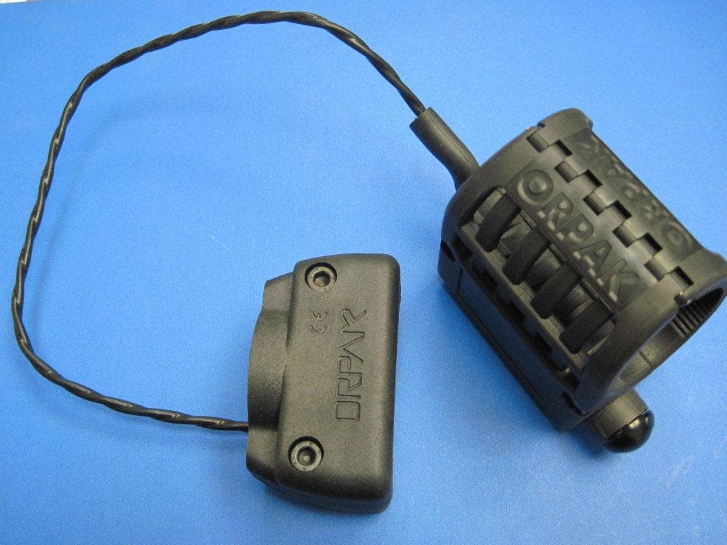
W8F800942XXX
Jul 08, 2013NOZZLE READER UNR
Equipment Class
DCD - Part 15 Low Power Transmitter Below 1705 kHz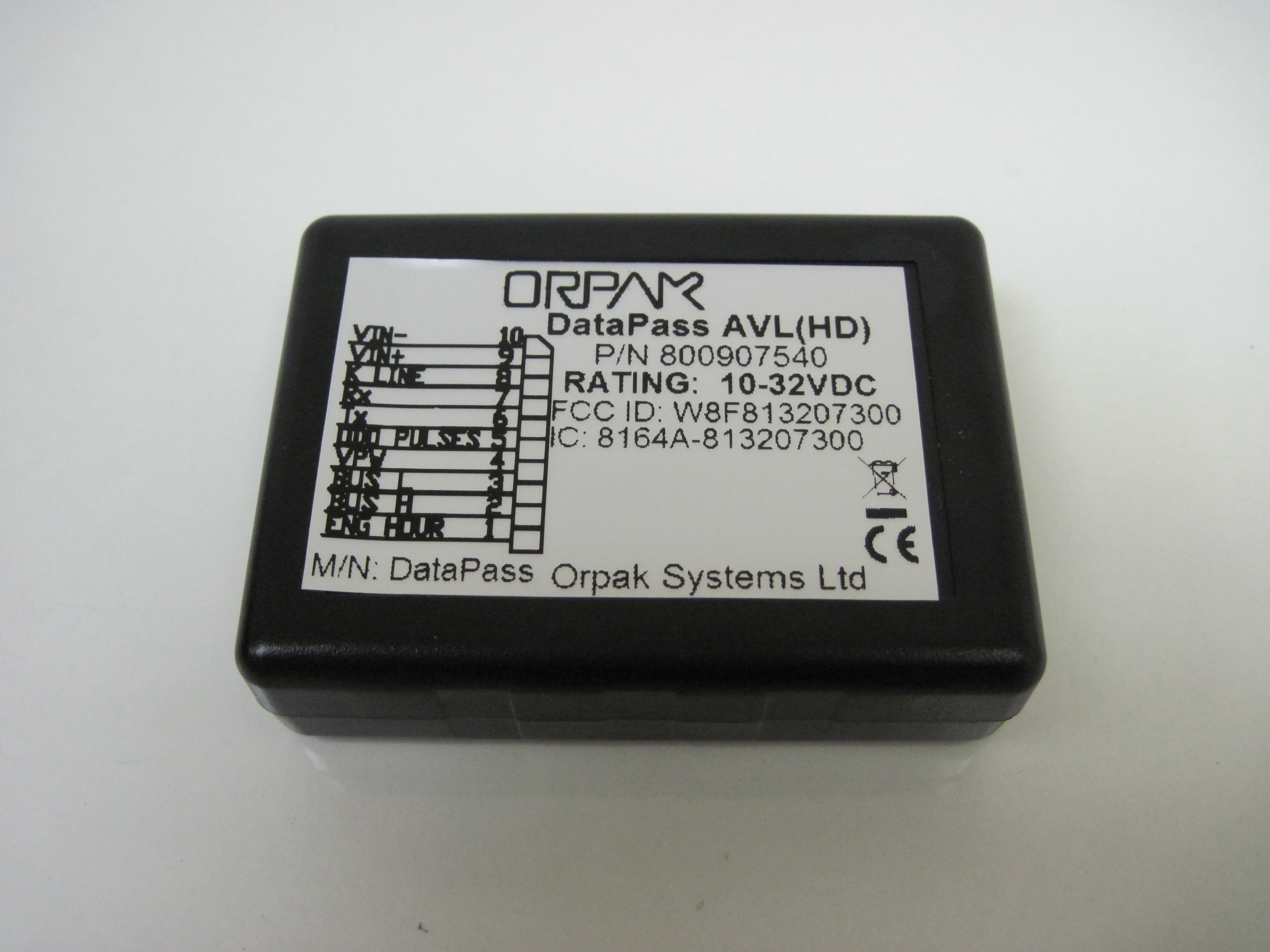
W8F813207300
Oct 14, 2012DATAPASS
Equipment Class
DTS - Digital Transmission System