W8F800939105NOZZLE READER
Orpak Systems Ltd.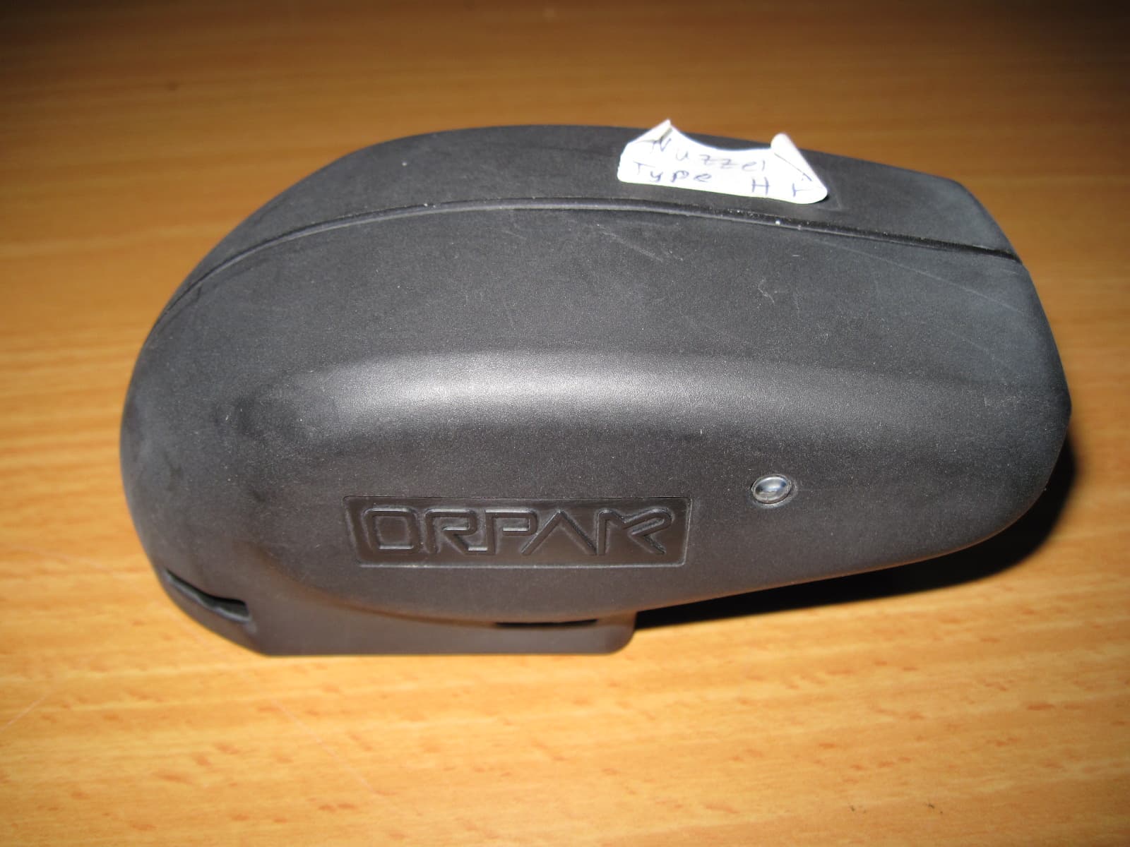
Click to zoom
Application Details
- Equipment Class
- DCD - Part 15 Low Power Transmitter Below 1705 kHz
- Date of Grant
- Nov 11, 2010
- Application Purpose
- Original Equipment
- Date of Application
- Nov 09, 2010
- Equipment Note
- NOZZLE READER
- Frequency Range
- 0.12500000 - 0.12500000
- Company
- Orpak Systems Ltd.
- Country
- Israel
Documents & Files
Document Text
Text extracted from the exhibit documents filed with the FCC. Open a document above to read the original.
Users Manual
Nozzle Reader Refueling Process – User Guide 1 N N o o z z z z l l e e R R e e a a d d e e r r R R e e f f u u e e l l i i n n g g P P r r o o c c e e s s s s – – U U s s e e r r G G u u i i d d e e Cat No. TBD 1.1. SCOPE This User Guide includes a general and functional description of the Wireless Nozzle Reader refueling process. 1.2. WIRELESS NOZZLE READER The following Wireless Nozzle Reader types are presented in this User Guide: Regular Wireless Nozzle Reader for standard 3/4" and 1" nozzles (see Figure 1-1) Wireless Nozzle Reader-H for heavy duty nozzles Wireless Nozzle Reader-T for tankers trucks The NR-H type (see Figure 1-3) is used for heavy duty nozzles used for refueling trucks / heavy vehicles. The NR-T type (see Figure 1-4) is actually a NR-H type used for tanker track; it differs only with the addition of an activation button pressed prior to the fueling process. Figure 1-1. Regular NR Installed on Pump Figure 1-2. Refueling Process Figure 1-4. NR-T Type Figure 1-3. NR-H Type Nozzle Reader Refueling Process – User Guide 2 1.3. REFUELING INSTRUCTIONS WARNING 1. NEVER ATTEMPT TO FUEL A VEHICLE WHILE IT IS RUNNING. 2. DO NOT REMOVE THE FILTER HOSE UNTIL THE FUEL FLOW HAS STOPPED 3. DO NOT TO TRY TO REMOVE OR TAMPER THE NR OR THE NR-H/T COILS Use the following instructions to start the refueling. 1. Be sure all ignition sources are off. 2. Remove nozzle from the pump you have selected. 3. Connect fueling nozzle to fuel receptacle on vehicle. To do this, remove plastic cover on vehicle fuel receptacle. 4. Press nozzle trigger 5. After connection is made, you will hear a small amount of fuel flow from the hose to the vehicle tank. 6. The refueling process automatically stops when the vehicle tank is full. 7. Return the nozzle to the dispenser. Insert the nozzle into the nozzle holder the same way you connected to the vehicle receptacle. 8. Return the plastic cover to the vehicle receptacle. Nozzle Reader Refueling Process – User Guide 3 This device complies with Part 15 of the FCC Rules. Operation is subject to the following two conditions: (1) This device may not cause harmful interference and (2) This device must accept any interference received, including interference that may cause undesired operation. THE FCC WANTS YOU TO KNOW: This equipment has been tested and found to comply with the limits or a Class A digital device, pursuant to part 15 of the FCC Rules. These limits are designed to provide reasonable protection against harmful interference when the equipment is operated in a commercial environment. This equipment generates, uses, and can radiate radio frequency energy and, if not installed and used in accordance with the instruction manual, may cause harmful interference to radio communications. Operation of this equipment in a residential area is likely to cause harmful interference in which case the user will be required to correct the interference at his own expense. THE FCC WANTS YOU TO KNOW: This equipment has been tested and found to comply with the limits for a Class B digital device, pursuant to part 15 of the FCC Rules. These limits are designed to provide reasonable protection against harmful interference in a residential area. This equipment generates, uses, and can radiate radio frequency energy and, if not installed and used in accordance with the instructions, may cause harmful interference to radio communications. However, there is no guarantee that interference will not occur in a particular installation. if this equipment does not cause harmful interference to radio or television reception, which can be determined by turning the equipment off and on, the user is encouraged to try to correct the interference by one or more of the following measures: Reorient or relocate the receiving antenna Increase the separation between the equipment and the receiver Connect the equipment to an outlet on a circuit different from that to which the receiver is connected Consult the dealer or an experienced radio/TV technician FCC Warning Modifications not expressly approved by the manufacturer responsible could void the user’s authority to operate the equipment under FCC rules.
Cover Letter(s)
REPLACE WITH OFFICIAL COMPANY LOGO / LETTERHEAD Date: 04.10. 10 Federal Communications Commission Authorization and Evaluation Division Confidentiality Request regarding application for certification of FCC ID: W8F800939105 Pursuant to Sections 0.457 and 0.459 of the Commission’s Rules, we hereby request confidential treatment of information accompanying this application as outlined below: CONF APPENDIX Nozzle Reader BlkDia.pdf CONF APPENDIX Nozzle Reader PartsLst.pdf CONF APPENDIX Nozzle Reader Schem.pdf CONF APPENDIX Nozzle Reader 2.4 GHz IntPho.pdf CONF APPENDIX Nozzle Reader 125 kHz IntPho.pdf The above materials contain trade secrets and proprietary information not customarily released to the public. The public disclosure of these materials may be harmful to the applicant and provide unjustified benefits to its competitors. The 2.4 GHz and 125 kHz transmitters are covered in epoxy. Removal of the epoxy will cause damage to the circuit boards and the transmitters will cease to function, In addition the first and second sides of the enclosure are secured together by a tamperproof screw and also with epoxy. This enclosure is also used as battery pack and according to Underwriters Laboratories " Unusual Fire and Explosion Hazards: Do not charge, disassemble and do not dispose of Nozzle Reader in fire – the internal batteries may explode." The applicant understands that pursuant to Section 0.457 of the Rules, disclosure of this application and all accompanying documentation will not be made before the date of the Grant for this application. Sincerely, Thank you, Signature: ______________ Printed Name: Gidi Segal Quality Assurance Director Orpak Systems Ltd.
Cover Letter(s)
REPLACE WITH OFFICIAL COMPANY LOGO / LETTERHEAD Date: 04.10.10 To Whom It May Concern We hereby authorize I.T.L. (Product Testing) Ltd (ITL) to act on our behalf regarding the FCC ID Change Process for the following application: FCC ID: W8F800939105 Thank you, Signature: ______________ Printed Name: Gidi Segal Quality Assurance Director Orpak Systems Ltd.
Cover Letter(s)
Date: 04.10.2010 attn: Reviewing Engineer Federal Communications Commission 7435 Oakland Mills Road Columbia, MD 21046 To Whom It May Concern: The Nozzle Reader FCC ID: W8F800939105 and label is so small that it cannot include the statement specified in FCC Part 15 Sub-part A, Section 15.19 (a) (3) “This device complies with Part 15 of the FCC Rules. Operation is subject to the following two conditions: (1) This device may not cause harmful interference and (2) This device must accept any interference received, including interference that may cause undesired operation." Due to this reason, we are using the provisions of Part 15 Sub-part A, Section 15.19 (a) (5) and this statement appears in a prominent location in the user manual. Please contact me if there is any information you may need. Sincerely, Gidi Segal Quality Assurance Director Orpak Systems Ltd. Tel: +972-3-577-6866 Fax: +972-3-579-6310 E-mail: [email protected] Website: www.orpak.com Fueling your business for success 3 Consider the environment - do you really need to print this email? CONFIDENTIAL!
Operational Description
The Nozzle Reader reads the vehicle information from the RFID FuelOpass and transmits it to the WGT over wireless channel and from there the data is sent to the station automation system for allowing/rejecting fueling. Nozzle Reader (NR) installed on ZVA Nozzle
Parts List/Tune Up Info
Date: 04.10.2010 To Whom It May Concern I hereby declare that there is no tune-up procedure for: FCC ID: W8F800939105 Thank you, Gidi Segal Quality Assurance Director Orpak Systems Ltd. Tel: +972-3-577-6866 Fax: +972-3-579-6310 E-mail: [email protected] Website: www.orpak.com Fueling your business for success 3 Consider the environment - do you really need to print this email? CONFIDENTIAL!
Test Report
DATE: 13 October 2010 I.T.L. (PRODUCT TESTING) LTD. FCC Radio Test Report for Orpak Systems Ltd. Equipment under test: Nozzle Reader Nozzle Reader-H Orpak Written by: _____________________________ D. Shidlowsky, Documentation Approved by: _____________________________ A. Sharabi, Test Engineer Approved by: _____________________________ I. Raz, EMC Laboratory Manager This report must not be reproduced, except in full, without the written permission of I.T.L. (Product Testing) Ltd. This report relates only to items tested. Test Report E94141.00 Orpak Systems Ltd. Page 1 of 57 FCC ACC M Ver 1.1 05Mayl 2000 Test Report E94141.00 Orpak Systems Ltd. Page 2 of 57 FCC ACC M Ver 1.1 05Mayl 2000 Measurement/Technical Report for Orpak Systems Ltd. Nozzle Reader Nozzle Reader-H Orpak FCC ID: W8F800939105 This report concerns: Original Grant: X Class I Change: Class II Change: Equipment type: Part 15 Low Power Transmitter Below 1705 kHz and Digital Transmission System Limits used: 47CFR15 Section 15.209, 15.247 Measurement procedure used is ANSI C63.4-2003. Application for Certification Applicant for this device: prepared by: (different from "prepared by") Ishaishou Raz Gideon Segal ITL (Product Testing) Ltd. Orpak Systems Ltd. Kfar Bin Nun 31 Lechi St. D.N. Shimshon 99780 P.O.B. 1461 Israel Bnei-Brak 5114 e-mail [email protected] Israel Tel: +972- 3 - 577 - 6868 Fax: +972- 6 - 579 - 6310 e-mail: gidi@orpak .com TABLE OF CONTENTS 1. GENERAL INFORMATION ------------------------------------------------------------------------------- 5 1.1 Administrative Information ................................................................................. 5 1.2 List of Accreditations ......................................................................................... 7 1.3 Product Description ........................................................................................... 8 1.4 Test Methodology .............................................................................................. 8 1.5 Test Facility ....................................................................................................... 8 1.6 Measurement Uncertainty ................................................................................. 8 2. SYSTEM TEST CONFIGURATION --------------------------------------------------------------------- 9 2.1 Justification ........................................................................................................ 9 2.2 EUT Exercise Software ..................................................................................... 9 2.3 Special Accessories .......................................................................................... 9 2.4 Equipment Modifications ................................................................................... 9 2.5 Configuration of Tested System ...................................................................... 10 3. TEST SETUP PHOTOGRAPH --------------------------------------------------------------------------11 4. FIELD STRENGTH OF FUNDAMENTAL 125 KHZ TRANSMITTER -------------------------12 4.1 Test Specification ............................................................................................ 12 4.2 Test Procedure ................................................................................................ 12 4.3 Test Results .................................................................................................... 12 4.4 Test Instrumentation Used, Field Strength of Fundamental ........................... 14 5. RADIATED EMISSION, 9 KHZ – 30 MHZ FOR LOW FREQUENCY TRANSMITTER (125 KHZ) ------------------------------------------------------------------------------15 5.1 Test Specification ............................................................................................ 15 5.2 Test Procedure ................................................................................................ 15 5.3 Test Results .................................................................................................... 15 5.4 Test Instrumentation Used, Radiated Measurements .................................... 18 5.5 Field Strength Calculation ............................................................................... 18 6. 6DB MINIMUM BANDWIDTH ---------------------------------------------------------------------------19 6.1 Test Specification ............................................................................................ 19 6.2 Test procedure ................................................................................................ 19 6.3 Test Results .................................................................................................... 21 6.4 Test Equipment Used. ..................................................................................... 22 7. 26DB MINIMUM BANDWIDTH -------------------------------------------------------------------------23 7.1 Test Specification ............................................................................................ 23 7.2 Test procedure ................................................................................................ 23 7.3 Test Results .................................................................................................... 25 7.4 Test Equipment Used. ..................................................................................... 26 8. RADIATED POWER OUTPUT --------------------------------------------------------------------------27 8.1 Test Specification ............................................................................................ 27 8.2 Test procedure ................................................................................................ 27 8.3 Test Results Calculation ................................................................................. 30 8.4 Test Equipment Used. ...................................................................................…
Text truncated - open the document above for the full version.
Contact Information
Applicant
Yair Elul(Quality Assurance Director)
Test Firm
Israel Testing LaboratoriesIIan Cohen
Technical Specifications
| # | Rule Parts | Frequency Range | Power Output |
|---|---|---|---|
| 1 | 15C | 0.125 MHz - 0.125 MHz | - |
Other Applications from Orpak Systems Ltd.
W8F819527450
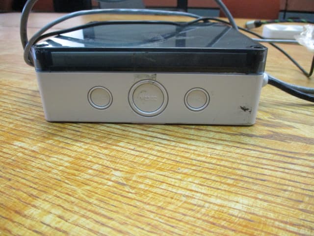
Aug 13, 2020nWGT-W Outdoor unit w/p.s., nWGT-W Outdoor unit w/o p.s, nWGT-W (Pump, SAMx1, LAN)
Equipment Class
DTS - Digital Transmission System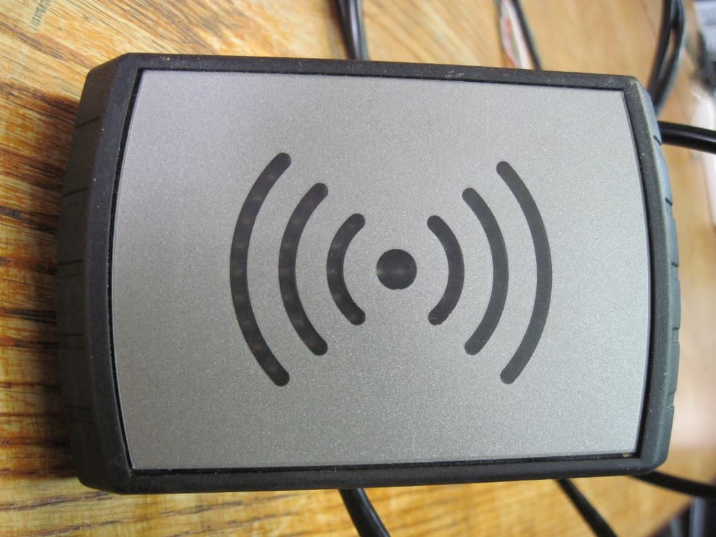
W8F800927160
Feb 26, 2020Tag Reader TR500
Equipment Class
DCD - Part 15 Low Power Transmitter Below 1705 kHz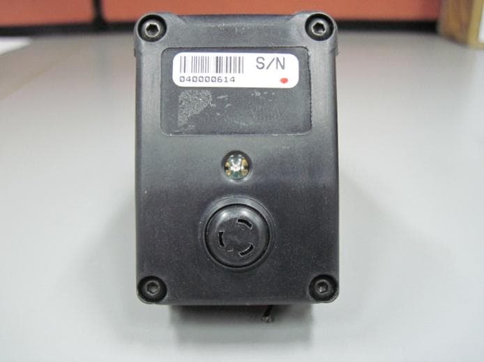
W8F800960000
Dec 22, 2014Fuel Pump Nozzle Reader NNR + Switch
Equipment Class
DCD - Part 15 Low Power Transmitter Below 1705 kHz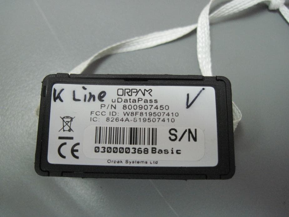
W8F819507450
Aug 04, 2014uDataPass
Equipment Class
DTS - Digital Transmission System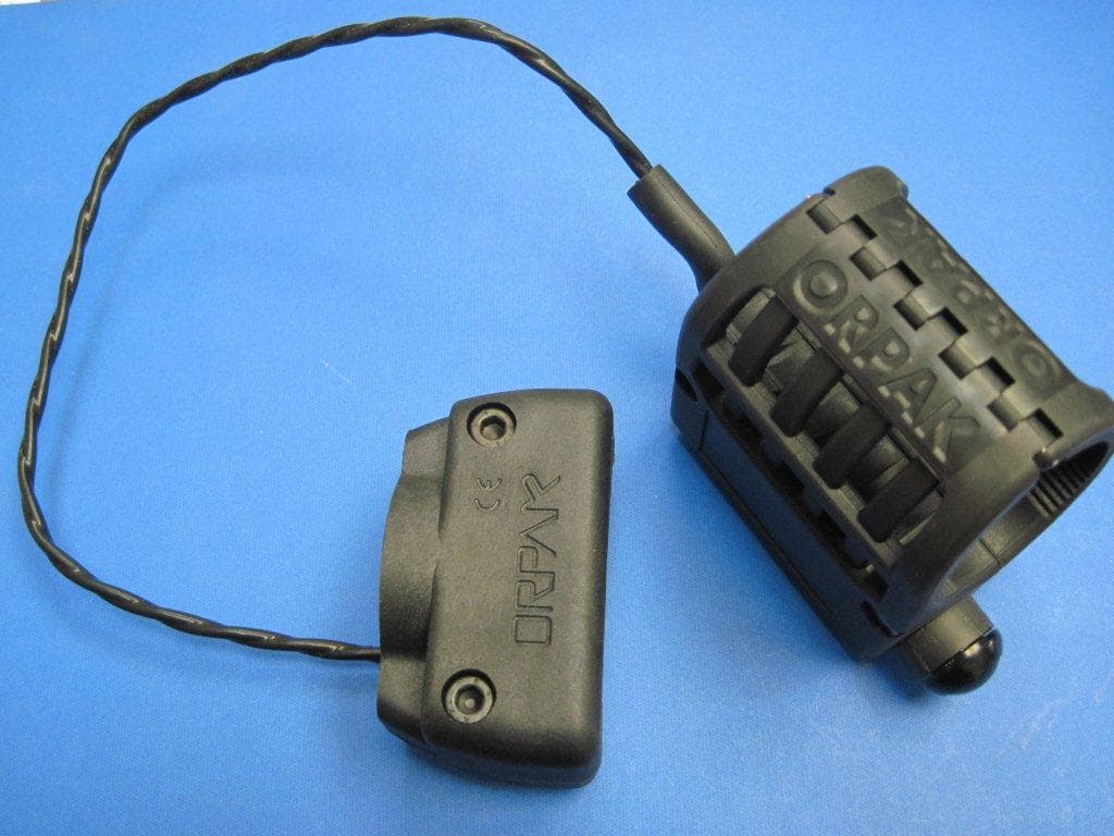
W8F800942XXX
Jul 08, 2013NOZZLE READER UNR
Equipment Class
DCD - Part 15 Low Power Transmitter Below 1705 kHz