WMUHAC-LBEEZigbee Module
Shenzhen HAC Telecom Technology Co. Ltd.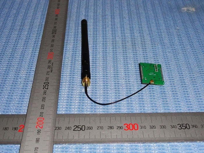
Click to zoom
Application Details
- Equipment Class
- DTS - Digital Transmission System
- Date of Grant
- Feb 20, 2014
- Application Purpose
- Original Equipment
- Date of Application
- Feb 20, 2014
- Equipment Note
- Zigbee Module
- Frequency Range
- 2405.00000000 - 2480.00000000
- Country
- China
Documents & Files
Document Text
Text extracted from the exhibit documents filed with the FCC. Open a document above to read the original.
Users Manual
HAC-LBee 2.4G Low Power Consumption Wireless Data Transmission Module (ZigBee Protocol) V 32.23.33 2013/11/07 User Manual SHENZHEN HAC TELECOM TECHNOLOGY CO., LTD Add: Fl.6, Building 2, Jiuxiangling New Industry Park, No.4227, Xilihu Road, Nanshan, Shenzhen, China. Te l : +86-755-23981078 Fax : +86-755-23981007 Email : [email protected] Web : http://www.rf-module-china.com ¾ High Performance 20dbm, 3.5Km (LOS, light of sight) ¾ Low Power Consumption Transmitting current: 150mA @ 20dBm Receiving current: 30mA @ 20dBm Sleep current: 3μA @ 20dBm ¾ MESH Network Self-organizing, Self-routing, Self-healing Point-to-point and Point-to-multipoint Transmission ¾ Simply To Use AT, API AT, Remote API AT command Transparent mode, API mode ¾ Standards Zigbee 2007 PRO ¾ High Reliability DSSS O-QPSK modulation CSMA-CA Automatic Backoff Mechanism Re-transmission and Response Mechanism ¾ High Security AES Encryption for Network Layer AES Encryption for Application Layer Catalog I. HAC-LBEE MODULE .................................................................................................................. 5 1 THE SIZE AND PIN ORDER OF LBEE MODULE..................................................................................... 5 2 PIN DEFINITION.................................................................................................................................. 5 3 TECHNICAL PARAMETERS................................................................................................................... 6 II. HAC-LBEE MODULE OPERATION ......................................................................................... 7 1 UART PORT INSTRUCTION............................................................................................................... 7 2 COMMUNICATION PROTOCOL............................................................................................................. 7 2.1 Transparent Mode ...................................................................................................................... 7 2.2 API Mode ................................................................................................................................... 7 3 AT COMMAND MODE......................................................................................................................... 7 3.1 Enter AT Command Mode .......................................................................................................... 8 3.2 Send AT Command ..................................................................................................................... 8 3.3 AT Command Response .............................................................................................................. 8 3.4 Exit AT Command Mode ............................................................................................................ 8 III. API OPERATION...................................................................................................................... 9 1 API FRAME FORMAT.......................................................................................................................... 9 2. API FRAME....................................................................................................................................... 9 2.1. Local AT Command Frame ....................................................................................................... 9 2.2. Response Frame for Local AT Command................................................................................ 10 2.3. Request Frame for Remote AT Command ............................................................................... 11 2.4. Response Frame for Remote AT Command............................................................................. 12 IV. AT COMMAND ....................................................................................................................... 14 1 ADDRESS COMMAND........................................................................................................................ 14 2 NETWORK COMMAND...................................................................................................................... 14 3 RF PARAMETER COMMAND.............................................................................................................. 16 4 SERIAL PORT PARAMETER COMMAND.............................................................................................. 16 5 I/O PARAMETER COMMAND............................................................................................................. 17 6 DIAGNOSTICS PARAMETER COMMAND............................................................................................. 17 7 AT COMMAND PARAMETER.............................................................................................................. 18 8 SLEEP COMMAND............................................................................................................................. 18 9 EXECUTE COMMAND........................................................................................................................ 19 V. LBEE ZIGBEE NETWORK....................................................................................................... 20 1 COORDINATOR.................................................................................................................................. 20 2 ROUTER............................................................................................................................................ 20 3 ENDDEVICE...................................................................................................................................... 21 3.1 The Relationship between Father node and Child node........................................................... 21 3.2 Child Node Capability...................................…
Text truncated - open the document above for the full version.
Cover Letter(s)
Date : February 11, 2014 Equipment Autorisation Division Federal Communications Commission 7435 Oakland Mills Road Columbia, MD 21046 FCC ID: _WMUHAC-LBEE ___ Product Name: Zigbee Module Request for Confidentiality Pursuant to Sections 0.457 and 0.459 of the commissions rules, we hereby request that the following documents be held confidential: • Schematics • Block diagram • Operational Description These materials contain trade secrets and proprietary information and are not customarily released to the public. The public disclosure of this information might be harmful to the company and provide unjustified benefits to our competitors. Dated this February 11, 2014 By: Koala Zhang Signature Printed Title: Sales Manager On behalf of : Shenzhen HAC Telecom Technology Co., Ltd. Telephone: 86-755-23981078
Cover Letter(s)
Product: Zigbee Module Model: HAC-LBee FCC ID: WMUHAC-LBEE Request for Modular Approval Attestation for the 2.4GHz Zigbee Module (i) The radio elements of the modular transmitter must have their own shielding. The physical crystal and tuning capacitors may be located external to the shielded radio elements. Answer: Yes Modular has shielding on the top and bottom sides, and full copper covered PCB board is used at bottom of module. (ii) The modular transmitter must have buffered modulation/data inputs (if such inputs are provided) to ensure that the module will comply with part 15 requirements under conditions of excessive data rates or over-modulation. Answer: Yes The EUT has buffered data inputs; it is integrated in chip CC2530F256 (iii) The modular transmitter must have its own power supply regulation. Answer: Yes Answer: Yes The EUT interface provides 3.3VDC, and on board IC CC2530F256 has its own VCO inside. (iv) The modular transmitter must comply with the antenna and transmission system requirements of §§15.203,15.204(b) and 15.204(c). The antenna must either be permanently attached or employ a “unique” antenna coupler (at all connections between the module and the antenna, including the cable). The “professional installation” provision of §15.203 is not applicable to modules but can apply to limited modular approvals under paragraph (b) of this section. Answer: Yes The EUT meets the antenna requirements. It is Dipole antenna with revised polarity connector. Refer to the photo shown in test report. (v) The modular transmitter must be tested in a stand-alone configuration, i.e., the module must not be inside another device during testing for compliance with part 15 requirements. Unless the transmitter module will be battery powered, it must comply with the AC line conducted requirements found in §15.207. AC or DC power lines and data input/output lines connected to the module must not contain ferrites, unless they will be marketed with the module (see §15.27(a)). The length of these lines shall be the length typical of actual use or, if that length is unknown, at least 10 centimeters to insure that there is no coupling between the case of the module and supporting equipment. Any Unique reversed antenna coupler is used. The device comply with 15.212 requirement: Single modular approval accessories, peripherals, or support equipment connected to the module during testing shall be unmodified and commercially available (see §15.31(i)). Answer: Yes The device was tested with stand –alone configuration, the distance between module and other supporting equipment is larger than 10cm. The conducted emissions are done. Please see page 10 and 11 of test report. (vi) The modular transmitter must be equipped with either a permanently affixed label or must be capable of electronically displaying its FCC identification number. Answer: Yes The modular has a permanent fixed label, and below statement was listed in the User Manual; The host device must be labelled to display the FCC ID of the module ‘Contains FCC ID: WMUHAC-LBEE (vii) The modular transmitter must comply with any specific rules or operating requirements that ordinarily apply to a complete transmitter and the manufacturer must provide adequate instructions along with the module to explain any such requirements. A copy of these instructions must be included in the application for equipment authorization. Answer: Yes The module comply with all specific rules applicable to the transmitter including all the conditions provided in the integration instructions by the grantee, Refer to test report and user manual . (viii) The modular transmitter must comply with any applicable RF exposure requirements in its final configuration. Answer: Yes Transmitter meets MPE calculation of 47 CFR 1.1307 . Refer to MPE Reports and Refer to modular installation manual. This modular complies with FCC RF radiation exposure limits set forth for an uncontrolled environment. This transmitter must not be co-located or operating in conjunction with any other antenna or transmitter. This modular must be installed and operated with a minimum distance of 20 cm between the radiator and user body. Dated this February 11, 2014 By: Koala Zhang Signature Printed Title: Sales Manager On behalf of : Shenzhen HAC Telecom Technology Co., Ltd. Telephone: 86-755-23981078
External Photos
Photo for the EUT
ID Label/Location Info
Product Name: Zigbee Module Model No.: LBee Trade Name: HAC FCC ID: WMUHAC-LBEE Input: DC3.3V Shenzhen HAC Telecom Technology Co., Ltd.
ID Label/Location Info
FCC Label Location
Internal Photos
Photo for the EUT Photo for the EUT
Test Report
ISO/IEC17025Accredited Lab. Report No: FCC 1312050 File reference No: 2014-01-15 Applicant: Shenzhen HAC Telecom Technology Co., Ltd Product: Zigbee Module Model No: HAC-LBee Trademark: N/A Test Standards: FCC Part 15 Subpart C, Paragraph 15.247 Test result: It is herewith confirmed and found to comply with the requirements set up by ANSI C63.4, FCC Part 15 Subpart C, Paragraph 15.247 regulations for the evaluation of electromagnetic compatibility Approved By Jack Chung Manager Dated: Jan 15, 2014 Results appearing herein relate only to the sample tested The technical reports is issued errors and omissions exempt and is subject to withdrawal at SHENZHEN TIMEWAY TECHNOLOGY CONSULTING CO., LTD 5/F,Block 4, Anhua Industrial Zone.,No.8 TaiRan Rd.CheGongMiao,FuTian District, Shenzhen,CHINA. Tel (755) 83448688 Fax (755) 83442996 Report No: 1312050 Page 2 of 47 Date: 2014-01-15 The report refers only to the sample tested and does not apply to the bulk. This report is issued in confidence to the client and it will be strictly treated as such by the Shenzhen Timeway Technology Consulting Co .,Ltd. It may not be reproduced rather in its entirety or in part and it may not be used for adverting. The client to whom the report is issued may, however, show or send it . or a certified copy there of prepared by the Shenzhen Timeway Technology Consulting co .,Ltd to his customer. Supplier or others persons directly concerned. Shenzhen Timeway Technology Consulting co .,Ltd will not, without the consent of the client enter into any discussion of correspondence with any third party concerning the contents of the report. In the event of the improper use of the report. The Shenzhen Timeway Technology Consulting co .,Ltd reserves the rights to withdraw it and to adopt any other remedies which may be appropriate. Special Statement: The testing quality ability of our laboratory meet with “Quality Law of People’s Republic of China” Clause 19. The testing quality system of our laboratory meet with ISO/IEC-17025 requirements, which is approved by CNAL. This approval result is accepted by MRA of APLAC. Our test facility is recognized, certified, or accredited by the following organizations: CNAL-LAB Code: L2292 The EMC Laboratory has been assessed and in compliance with CNAL/AC01:2002 accreditation criteria for testing Laboratories (identical to ISO/IEC 17025:1999 General Requirements) for the Competence of testing Laboratories. FCC-Registration No.: 899988 The EMC Laboratory has been registered and fully described in a report filed with the (FCC) Federal Communications commission. The acceptance letter from the FCC is maintained in our files. Registration No.: 899988. IC- Registration No.: IC5205A-02 The EMC Laboratory has been registered and fully described in a report filed with the (IC) Industry Canada. The acceptance letter from the IC is maintained in our files. Registration IC No.: 5205A-02. Report No: 1312050 Page 3 of 47 Date: 2014-01-15 The report refers only to the sample tested and does not apply to the bulk. This report is issued in confidence to the client and it will be strictly treated as such by the Shenzhen Timeway Technology Consulting Co .,Ltd. It may not be reproduced rather in its entirety or in part and it may not be used for adverting. The client to whom the report is issued may, however, show or send it . or a certified copy there of prepared by the Shenzhen Timeway Technology Consulting co .,Ltd to his customer. Supplier or others persons directly concerned. Shenzhen Timeway Technology Consulting co .,Ltd will not, without the consent of the client enter into any discussion of correspondence with any third party concerning the contents of the report. In the event of the improper use of the report. The Shenzhen Timeway Technology Consulting co .,Ltd reserves the rights to withdraw it and to adopt any other remedies which may be appropriate. Test Report Conclusion Content 1.0 General Details ................................................................................................ 4 1.1 Test Lab Details................................................................................................ 4 1.2 Applicant Details.............................................................................................. 4 1.3 Description of EUT .......................................................................................... 4 1.4 Submitted Sample............................................................................................. 5 1.5 Test Duration.................................................................................... 5 1.6 Test Uncertainty.................................................................................. 5 1.7 Test By.......................................................................................................... 5 2.0 List of Measurement Equipment......................................................................... 6 3.0 Technical Details............................................................................................. 7 3.1 Summary of Test Results..................................................................................... 7 3.2 Test Standards.................................................................................................. 7 4.0 EUT Modification.............................................................................................7 5.0 Power Line Conducted Emission Test...................................................................... 8 5.1 Schematics of the Test........................................................................................ 8 5.2 Test Method and Test Procedure............................................................................ 8 5.3 Configuration of the EUT.................................................................................... 8 5.4 EUT Operating Condition....................................................................................9…
Text truncated - open the document above for the full version.
Test Setup Photos
Conducted Emission Test Setup: Radiated Emission Test Setup:
Contact Information
Applicant
Koala Zhang(CEO)
Test Firm
Shenzhen Timeway Testing LaboratoriesJack Chung
Technical Specifications
| # | Rule Parts | Frequency Range | Power Output |
|---|---|---|---|
| 1 | 15C | 2.40 GHz - 2.48 GHz | 92.90 mW |
Other Applications from Shenzhen HAC Telecom Technology Co. Ltd.

WMUHAC-GWW1-M
May 11, 2023LoRaWAN Gateway
Equipment Class
JAB - Part 15 Class B Digital Device
WMUHAC-WRW-E1
Apr 22, 2023Pulse reader for Elster
Equipment Class
DXX - Part 15 Low Power Communication Device Transmitter
WMUHAC-WRW-I1
Apr 22, 2023Pulse reader for Itron
Equipment Class
DXX - Part 15 Low Power Communication Device Transmitter
WMUHAC-UBEEV3X
Apr 11, 2011Zigbee Module
Equipment Class
DTS - Digital Transmission System