WMUHAC-WRW-I1Pulse reader for Itron
Shenzhen HAC Telecom Technology Co. Ltd.
Click to zoom
Application Details
- Equipment Class
- DXX - Part 15 Low Power Communication Device Transmitter
- Date of Grant
- Apr 22, 2023
- Application Purpose
- Original Equipment
- Date of Application
- Apr 22, 2023
- Equipment Note
- Pulse reader for Itron
- Frequency Range
- 903.30000000 - 926.80000000
- Country
- China
Documents & Files
Document Text
Text extracted from the exhibit documents filed with the FCC. Open a document above to read the original.
Users Manual
WRW-I1 electronic backpack Installation and operation instructions WRW-I1 pulse reader P1 Content 1. Overview ....................................................................................................................................................................................................... 2 2. Metering Module Feature ....................................................................................................................................................................... 2 2.1. Electrical characteristics .............................................................................................................................................................. 2 2.2. Feature Description ...................................................................................................................................................................... 2 2.3. LED indicator of metering module ......................................................................................................................................... 3 3. Product Assembly ...................................................................................................................................................................................... 4 4. Operating instructions for metering module .................................................................................................................................. 5 5. Precautions and handling of common problems ......................................................................................................................... 6 6. Instruction of production configuration tool ................................................................................................................................. 6 6.1. Tool list ............................................................................................................................................................................................. 6 6.2. Device connection ........................................................................................................................................................................ 6 6.4. Supported software ..................................................................................................................................................................... 8 6.4.1. Software installation ....................................................................................................................................................... 8 6.5.Production Test Flow ................................................................................................................................................................. 11 6.6. Precautions for production setup ........................................................................................................................................ 12 7.Infrared upgrade function .................................................................................................................................................................... 13 7.1 Supported software ................................................................................................................................................................... 13 7.1.1 Software installation ..................................................................................................................................................... 13 7.1.2 Software interface ......................................................................................................................................................... 13 7.2. Upgrading Flow .......................................................................................................................................................................... 13 Disclaimers ..................................................................................................................................................................................................... 15 WRW-I1 pulse reader P2 1. Overview The Pulse Reader (ID: WRW-I1) integrates hall metering, acquisition, communication and transmission. It can be able to monitor abnormal conditions such as magnetic interference, low voltage of battery and disassembly in real time, and actively report it to the management platform. The pulse reader and the gateway form a star network, which is convenient for network maintenance, with high reliability and strong scalability. It complies with LoRaWAN1.0.2 standard protocol. 2. Metering Module Feature 2.1. Electrical characteristics No. Feature Function Description 1 Working frequency It’s compatible with LoRaWAN®,EU868,AU915 are optional 2 Maximum transmitting power It’s in accordance with the requirements of power limit in different areas of the LoRaWAN protocol 3 Working temperature -20°C ~ +55°C 4 Working voltage +3.2V ~ +3.8V 5 Transmitting distance > 10km 6 Lifespan > 8 years ( use one ER18505 lithium battery ) 7 Waterproof degree IP68 2.2. Feature Description No. Feature Function Description 1 Data reporting There are two ways to report data Touch to report data: you must touch the touch button twice, long touch (more than 2 seconds)+short touch (less than 2 seconds), and the two actions must be completed within 5 seconds, otherwise the trigger is invalid. Timed active submission of data: the periodic reporting period and the periodic reporting time can be set. The periodic reporting range is 600~86400S, and the periodic reporting time range is 0~23H. After setting, the reporting time is calculated according to the device's DeviceEui, scheduled reporting cycle and scheduled reporting time. The default value of regular reporting period is 28800S, and the default value of regular reporting time is 6H. 2 Measurement The non-magnetic metering method is supported. 3 Power-down storage It supports power-off storage, and does no…
Text truncated - open the document above for the full version.
Attestation Statements
Shenzhen HAC Telecom Technology Co., LTD * the applicant must designate a contact located in the United States for purposes of acting as the applicant’s agent for service of process, regardless of whether the applicant is a domestic or foreign entity. An applicant located in the United States may designate itself as the agent for service of process. U.S. Agent Designation for Service of Process - Certification Attestation Letter 4/21/2023 ATTN.: Reviewing Engineer Per section 2.911(d)(7) of the FCC rules, Shenzhen HAC Telecom Technology Co., LTD (“the applicant”) certifies that the equipment for which authorization is sought is designated to the following U.S. agent* for service of process: Company Name: JOC Australia Inc Physical U.S. Company Address: 18351 Colima Road Ste 585 Rowland Heights,California,91748 United States of America Agent contact name/Title : Benjamin.Smith/Vice President Agent Email Address: [email protected]/[email protected] Tel No.: +1(626) 217 4778 FRN No.: 0033379421 The above contact person accepts the obligation for service of process. The applicant accepts to maintain an agent for no less than one year after the grantee has terminated all marketing and importation or the conclusion of any Commission-related proceeding involving the equipment. Applicant Signed: Agent Signed (if different to Applicant): Signed: Signed: Printed name: Koala Zhang Printed name: Benjamin. Smith Title: CEO Title: Vice President Company Name: Shenzhen HAC Telecom Company Name: JOC Australia Inc Technology Co., LTD Date: 4/21/2023 Date: 4/21/2023
Cover Letter(s)
Shenzhen HAC Telecom Technology Co., LTD Agent Authorization Company: Shenzhen HAC Telecom Technology Co., LTD Address: Fl 9, Block A, Bldg 1, Shenzhen International Innovation Valley, Xingke 1st Street, Nanshan, Shenzhen, China Product Name: Pulse reader for Itron Model Number(s): WRW-I1 Product Description: Pulse reader for Itron We authorize MiCOM Labs Inc., 575 Boulder Court, Pleasanton, California 94566, USA, to act on our behalf on all matters concerning the certification of above named equipment. We declare that MiCOM Labs Inc. is allowed to forward all information related to the approval and certification of equipment to the regulatory agencies as required and to discuss any issues concerning the approval application. Any and all acts carried out by MiCOM Labs on our behalf shall have the same effect as acts of our own. Signature: Date: 2023.03.31 Name: Jiankuai Li Title: PM Company: SHENZHEN STS TEST SERVICES CO.,LTD.
Cover Letter(s)
Shenzhen HAC Telecom Technology Co., LTD Office of Engineering Technology Federal Communications Commission 7435 Oakland Mills Road Columbia, MD 21046 USA Date: 2023.03.31 Subject; Request for Confidentiality FCC ID: WMUHAC-WRW-I1 To Whom It May Concern, Pursuant to the provisions of the Commission’s rules Title 47 Sections §0.457 and §0.459, we are requesting the Commission to withhold the following attachment(s) as confidential documents from public disclosure indefinitely. These documents contain detailed system and equipment descriptions and are considered as proprietary information in operation of the equipment. The public disclosure of these documents might be harmful to our company and would give competitors an unfair advantage in the market. Schematic Diagram Block Diagram Operational Description In additional to above mentioned documents, in order to comply with the marketing regulations in Title 47 CFR §2.803 and the importation rules in Title 47 CFR §2.1204, while ensuring that business sensitive information remains confidential until the actual marketing of newly authorized devices, we request Short Term Confidentiality of the following attachment(s); External Photos Test Setup Photos Internal Photos User Manual For 45 days, pursuant to Public Notice DA 04-1705. OR For 180 days pursuant to KDB 726920 D01. It is our understanding that all measurement test reports, FCC ID label format and correspondence during the certification review process cannot be granted as confidential documents and this information will be available for public review once the grant of equipment authorization is issued. Signature: Date: 2023.03.31 Name: Jiankuai Li Title: PM Company: SHENZHEN STS TEST SERVICES CO.,LTD.
External Photos
Page 1 of 3 Report No.: STS2302124 APPENDIX-PHOTOGRAPHS OF EUT CONSTRUCTIONAL DETAILS Model: WRW-I1 Photo 1 Photo 2 Page 2 of 3 Report No.: STS2302124 Photo 3 Photo 4 Page 3 of 3 Report No.: STS2302124 Photo 5 Photo 6
ID Label/Location Info
FCC Label W:20mm L:45mm Pulse reader for Itron Model: WRW-I1 FCC ID: WMUHAC-WRW-I1
Internal Photos
Page 1 of 3 Report No.: STS2302124 APPENDIX-PHOTOGRAPHS OF EUT CONSTRUCTIONAL DETAILS Model: WRW-I1 Photo 1 Photo 2 Page 2 of 3 Report No.: STS2302124 Photo 3 Photo 4 SRD Antenna Page 3 of 3 Report No.: STS2302124 Photo 5
RF Exposure Info
Any reproduction of this document must be done in full. No single part of this document may be reproduced without permission from STS, all test data presented in this report is only applicable to presented test sample. Shenzhen STS Test Services Co., Ltd. A 1/F, Building B, Zhuoke Science Park, No.190 Chongqing Road, HepingShequ, Fuyong Sub-District, Bao’an District, Shenzhen, Guang Dong, China TEL: +86-755 3688 6288 FAX: +86-755 3688 6277 E-mail:[email protected] RADIO TEST REPORT Report No: STS2302124H02 Issued for Shenzhen HAC Telecom Technology Co., LTD Fl 9, Block A, Bldg 1, Shenzhen International Innovation Valley, Xingke 1st Street, Nanshan, Shenzhen, China Product Name: Pulse reader for Itron Brand: Model Number: WRW-I1 Series Model(s): N/A FCC ID: WMUHAC-WRW-I1 Test Standard: FCC 47CFR §2.1093 S T L A B S Page 2 of 9 Report No.: STS2302124H02 Test Report Certification Applicant’s Name ................. : Shenzhen HAC Telecom Technology Co., LTD Address ................................. : Fl 9, Block A, Bldg 1, Shenzhen International Innovation Valley, Xingke 1st Street, Nanshan, Shenzhen, China Manufacturer's Name .......... : Shenzhen HAC Telecom Technology Co., LTD Address ................................. : Fl 9, Block A, Bldg 1, Shenzhen International Innovation Valley, Xingke 1st Street, Nanshan, Shenzhen, China Product Description Product Name ........................ : Pulse reader for Itron Brand ................................... : Model Number ....................... : ... : WRW-I1 Series Model(s) ..................... : N/A Standards ............................. : FCC 47CFR §2.1093 447498 D04 Interim General RF Exposure Guidance v01 This report shall not be reproduced except in full, without the written approval of STS, this document only be altered or revised by STS, personal only, and shall be noted in the revision of the document. Date of Test ........................................... : Date of receipt of test item ..................... : 21 Feb. 2023 Date (s) of performance of tests ............. : 21 Feb. 2023 ~ 30 Mar. 2023 Date of Issue .......................................... : 30 Mar. 2023 Test Result.............................................. : Pass Testing Engineer : (Chris Chen) Technical Manager : (Sean she) Authorized Signatory : (Bovey Yang) Page 3 of 9 Report No.: STS2302124H02 TABLE OF CONTENTS 1. GENERAL INFORMATION 5 1.1 GENERAL DESCRIPTION OF THE EUT 5 1.2 TEST FACTORY 5 2. FCC 47CFR §2.1091 REQUIREMENT 6 2.1 TEST STANDARDS 6 2.2 LIMIT 6 2.3 TEST RESULT 9 Page 4 of 9 Report No.: STS2302124H02 Revision History Rev. Issue Date Report No. Effect Page Contents 00 30 Mar. 2023 STS2302124H02 ALL Initial Issue Page 5 of 9 Report No.: STS2302124H02 1. GENERAL INFORMATION 1.1 GENERAL DESCRIPTION OF THE EUT Product Name Pulse reader for Itron Brand Model Number WRW-I1 Series Model(s) N/A Model Difference N/A Product Description The EUT is Pulse reader for Itron. Operation Frequency: 903.3-926.8MHz Modulation Type: GFSK Antenna gain: 0dBi Antenna Designation: Helical Antenna Battery Rated Voltage:3.6V Charge Limit Voltage: Not rechargeable Capacity: 4000mAh Hardware Version HAC-MLWA7 Software Version HAC-WRW-I1 1.2 TEST FACTORY SHENZHEN STS TEST SERVICES CO., LTD Add. : A 1/F, Building B, Zhuoke Science Park, No.190 Chongqing Road, HepingShequ, Fuyong Sub-District, Bao’an District, Shenzhen, Guang Dong, China FCC test Firm Registration Number: 625569 IC test Firm Registration Number: 12108A A2LA Certificate No.: 4338.01 Page 6 of 9 Report No.: STS2302124H02 2. FCC 47CFR §2.1091 REQUIREMENT 2.1 TEST STANDARDS Follow the maximum permissible exposure (MPE) limits specified in 447498 D04 Interim General Radio Frequency Exposure Guidelines v01. The gain of the antenna used in the product was extracted from the supplied antenna data sheet and the maximum total power input to the antenna was also measured. Calculate the distance from the product to the MPE limit by the formula. 2.2 LIMIT For single RF sources (i.e., any single fixed RF source, mobile device, or portable device, as defined in paragraph (b)(2) of this section): A single RF source is exempt if: (A) The available maximum time-averaged power is no more than 1 mW, regardless of separation distance. This exemption may not be used in conjunction with other exemption criteria other than those in paragraph (b)(3)(ii)(A) of Part 1.1307. Medical implant devices may only use this exemption and that in paragraph (b)(3)(ii)(A); (B) Or the available maximum time-averaged power or effective radiated power (ERP), whichever is greater, is less than or equal to the threshold Pth (mW) described in the following formula. This method shall only be used at separation distances (cm) from 0.5 centimeters to 40 centimeters and at frequencies from 0.3 GHz to 6 GHz (inclusive). Pth is given by: Page 7 of 9 Report No.: STS2302124H02 (C) Or using below table and the minimum separation distance (R in meters) from the body of a nearby person for the frequency (f in MHz) at which the source operates, the ERP (watts) is no more than the calculated value prescribed for that frequency. For the exemption in Table 1 to apply, R must be at least λ/2π, where λ is the free-space operating wavelength in meters. If the ERP of a single RF source is not easily obtained, then the available maximum time-averaged power may be used in lieu of ERP if the physical dimensions of the radiating structure(s) do not exceed the electrical length of λ/4 or if the antenna gain is less than that of a half-wave dipole (1.64 linear value). RF Source frequency (MHz) Threshold ERP(watts) 0.3-1.34 1,920 R 2 . 1.34-30 3,450 R 2 /f 2 . 30-300 3.83 R 2 . 300-1,500 0.0128 R 2 f. 1,500-100,000 19.2R 2 . Page 8 of 9 Report No.: STS2302124H02 For multiple RF sources: Multiple RF sources are exempt if: (A) The available maximum time-averaged power of each source is no more than 1 mW and there is a separation distance of two centimeters between any portion of a radia…
Text truncated - open the document above for the full version.
Test Report
- 1 - SPECIFICATION FOR APPROVAL CUSTOMER:Shenzhen HAC Telecom Technology Co., Ltd. CUSTOMER PARTNO: SUPPLIER:ShenZhen MyAntenna RF Technology Co.,Ltd PRODUCT MODEL:HAC-TH915-A21F01 PRODUCT NAME:HAC-TH915-A21F01 Spring antenna PRODUCT CODE:M04-0102130R0A CUSTOMER SIGNATURE: CUSTOMER SEAL: SUPPLIER SIGNATURE: SUPPLIER SEAL: NOTE: PLEASE RETURN THIS COPY AS A CERTIFICATION OF YOUR APPROVAL Prepared by: Date: 2022.08.30 Add: Tel: 0755-86503881 Fax: 0755-27801677 - 2 - VERSION INFORMATION Versio n DATE REVISION DESCRIPTION PREPARED CHECKE D APPROVED V1.0 2022.08.3 0 First issue - 3 - PERFORMANCE PARAMETER 1. Electrical Characteristics 1 Frequency Range 880MHz-960MHz 2 V.S.W.R <3.0 3 Gain 0 dBi 4 Impendence 50Ω 5 Polarization Vertical polarization 2. Mechanical parameters 1 Measure Φ0.6mm 2 Colour Silvery white 3. Environment Condition 1 Working Temp -30°C~80°C - 4 - TESTING CURVE 1. Matching circuit - 5 - TESTING CURVE 2. Performance test 2.1 V.S.W.R Data list Freq/MHz 880 915 960 VSWR 2.27 1.47 2.39 - 6 - TESTING CURVE 3. Passive testing 3.1 Efficiency and Gain - 7 - Data list Freq(MHz) Gain(dBi) Efficiency(%) 880 -1.07 43.67 885 -0.74 44.08 890 -0.37 44.35 895 0.15 46.20 900 -0.57 47.81 905 -0.94 49.41 910 -0.85 47.68 915 0.00 45.95 920 -0.64 45.33 925 -0.90 48.90 930 -0.87 48.70 935 -0.85 51.34 940 -0.60 53.29 945 -0.35 53.85 950 -0.32 54.48 955 -0.04 51.00 960 -0.41 45.48 - 8 - 3.2 3D Map TESTING CURVE 3.3 2D Figure 1 2 3 4 5 6 7 8 RoHS Compliant A G P A 40.73±0.5 31.23±0.5 B B 20.63±0.5 (P=3.6 4c;P=1.5 3.75± 1c ) 8 C C Note: 1.The wire diameter is 0.6mm, and the wire diameter tolerance is ± 0.05; The material is stainless steel nickel-plated wire, which can be easily soldered; Salt fog lasts for 48 hours. 2.All unmarked corners are right angles. 3.All unmarked corner tolerances are ± 2 degrees. 4.The recommended size of the outer arc of all corners is R1.0-R1.2. 5.The surface shall be smooth and clean without oil stain, deformation, scar, sharp corner and burr. 6.The material complies with ROHS. ShenZhen MyAntenna RF Technology Co.,Ltd Third Angle D 0~10 ± 0 . 05 10~18 ±0.10 18~30 ±0.12 30~40 ±0.15 Project 0.02 Part Name Φ0.03 Part No. 0.02 Material HAC-TH915-A21F01 弹簧 M04-0102130R0A Date Designed by D Checked by MD RF A Rev New drawing Description 1 20220830 Date 0.04 Treatment Approved by 3 Remark 4 40~ ± 0.20 Angle ±0.5° Color 5 6 Unit mm 7 Scale 1:1 Rev A 8 2 SC HE DU L E DRA W ING 3.9 0 ± 0 . 3 - 9 - - 10 - ANTENNA PLACEMENT DIAGRAM - 11 - Certificate of Acceptance Sample Size Inspection Report Item name HAC-TH915-A21F01 Antenna type Spring antenna Date 2022.08.30 Visual inspection standard 1.The antenna surface is normal Dimensional inspection standard 2.Within the tolerance range required by the drawing No. Inspectio n items Specificati ons Inspecti on tools Number of samples Determ ine Description 1 Appearan ce Above standards Visual 3 OK 2 Size As below Vernier caliper 3 OK No. Inspection items Specificati ons Inspectio n tools Test results (including 6 data recorded at the highest and lowest values) 1 2 3 4 5 6 1 Overall dimensio n 40.75±0.5 Caliper s 2 Φ5.6±0.1 3 31.23±0.5 4 3.9±0.3 5 20.63±0.5 6 7 8 Not e Approval: Checked: Inspector: - 12 - QC ENGINEERING DRAWING Documentat ion MA-QCW-2208- 044 Documentat ion name HAC-TH915-A21F01 Spring antenna Authorize Version 本 A Check QC Engineering Drawing Release date 2022.08.30 Effective date 2022.08.30 Page 1/1 Approval N o. Flow Process name Process parameters /quality characteristics Use equipment fixture Detection equipment Inspectio n method Inspection frequency Usage record Undertaker Relevant documents 1 Incoming inspection Inspection standard/drawing Calipers / Visual AQL spot check IQC inspection report IQC 2 Confirmation of packaging (bagging) quantity / / / Visual Full inspection Daily production report Operator 3 Warehousing MO / / / / Product warehousing order 单 Warehous e keeper 4 Pre-shipment inspection / / / / Spot check 检 Spot check report OQC Explain: Operation and processing; Confirmation,inspection,judgment,approval; Store; Handling; Mark Modify content Version Date Modified by Approval First issue A 2022.08.30 - 13 - ROHS TEST REPORT Project material name Material code Report test sample name Testing organization Detection time Test report No Test conclusion Remarks HAC-TH915- A21F01 M04-0102130R0A Nickel plated stainless steel SGS 2022.03.2 1 SZXEC2200395905 OK Prepared by: Checked: Date:2022.08.30 Seal : - 14 - PRODUCT VERIFICATION Test items Test description/test standard Objective requirements Product validation(PV) Remark Sample Test site Test Respo nsible Quan tity Ty pe Cli ent Sup ply Third party Conclu sion Visual inspection The surface shall be free of dents, scratches, cracks, deformation, burrs, mildew and other defects; The surface coating shall not blister, crack or fall off; Metal parts shall be free of rust and other mechanical damage; The filling material shall not overflow. Normal appearance Full inspe ction T o o li n g √ OK Dimension As drawing size Within dimension tolerance 3pc s T o o l i n g √ OK Performance check The product meets the requirements in the design specification Short circuit and continuity test Full inspe ction T o o l i n g √ OK Salt fog resistance 48-hour salt spray test No rust on the surface after cyclic verification 3pc s / √ OK Requirements for prohibited and restricted substances Test according to RoHs requirements Products shall co mply with RoHs standards / / √ OK Packaging specification Place according to the drawing specifications Visual inspection and placement as required Full inspe ction T o o l i n g √ OK - 15 - BOM DETAILS No. Part No. Product Name Version Specification description Colour Unit Consu mption 1 M04-0102130R0A Spring antenna V1.0 Silvery,NB Antenna,Soldering,Nickel plating onΦ0.6mm stainless steel,Φ 5.6*40.73mm,盐雾过 48H Silvery white PCS 1 2 3 4 5 6 7
Test Report
Any reproduction of this document must be done in full. No single part of this document may be reproduced without permission from STS, All Test Data Presented in this report is only applicable to presented Test sample. Shenzhen STS Test Services Co., Ltd. A 1/F, Building B, Zhuoke Science Park, No.190 Chongqing Road, HepingShequ Fuyong Sub-District, Bao’an District, Shenzhen, Guang Dong, China TEL: +86-755 3688 6288 FAX: +86-755 3688 6277 E-mail:[email protected] RADIO TEST REPORT Report No.: STS2302124W02 Issued for Shenzhen HAC Telecom Technology Co., LTD Fl 9, Block A, Bldg 1, Shenzhen International Innovation Valley, Xingke 1st Street, Nanshan, Shenzhen, China Product Name: Pulse reader for Itron Brand: Model Number: WRW-I1 Series Model(s): N/A FCC ID: WMUHAC-WRW-I1 Test Standard: FCC Part 15.249 S T L A B S Page 2 of 34 Report No.: STS2302124W02 TEST RESULT CERTIFICATION Applicant’s Name .................: Shenzhen HAC Telecom Technology Co., LTD Address ..................................: Fl 9, Block A, Bldg 1, Shenzhen International Innovation Valley, Xingke 1st Street, Nanshan, Shenzhen, China Manufacture's Name ............: Shenzhen HAC Telecom Technology Co., LTD Address ..................................: Fl 9, Block A, Bldg 1, Shenzhen International Innovation Valley, Xingke 1st Street, Nanshan, Shenzhen, China Product Description Product Name ........................: Pulse reader for Itron Brand .....................................: Model Number ........................: WRW-I1 Series Model(s) ......................: N/A Test Standards ......................: FCC Part15.249 Test Procedure .......................: ANSI C63.10-2013 This device described above has been tested by STS, the test results show that the equipment under test (EUT) is in compliance with the FCC requirements. And it is applicable only to the tested sample identified in the report. This report shall not be reproduced except in full, without the written approval of STS, this document only be altered or revised by STS, personal only, and shall be noted in the revision of the document. Date of Test ............................: Date of receipt of test item ......: 21 Feb. 2023 Date of performance of tests ..: 21 Feb. 2023 ~ 30 Mar. 2023 Date of Issue ..........................: 30 Mar. 2023 Test Result .............................: Pass Testing Engineer : (Chris Chen) Technical Manager : (Sean she) Authorized Signatory : (Bovey Yang) Page 3 of 34 Report No.: STS2302124W02 Table of Contents Page 1. SUMMARY OF TEST RESULTS 5 1.1 TEST FACTORY 6 1.2 MEASUREMENT UNCERTAINTY 6 2. GENERAL INFORMATION 7 2.1 GENERAL DESCRIPTION OF THE EUT 7 2.2 DESCRIPTION OF THE TEST MODES 9 2.3 TEST SOFTWARE AND POWER LEVEL 9 2.4 BLOCK DIGRAM SHOWING THE CONFIGURATION OF SYSTEM TESTED 10 2.5 DESCRIPTION OF NECESSARY ACCESSORIES AND SUPPORT UNITS 11 2.6 EQUIPMENTS LIST FOR ALL TEST ITEMS 12 3. EMC EMISSION TEST 13 3.1 CONDUCTED EMISSION MEASUREMENT 13 3.2 RADIATED EMISSION MEASUREMENT 15 4. BANDWIDTH TEST 30 4.1 TEST PROCEDURE 30 4.2 TEST SETUP 30 4.3 EUT OPERATION CONDITIONS 30 4.4 TEST RESULTS 31 5. ANTENNA REQUIREMENT 33 5.1 STANDARD REQUIREMENT 33 5.2 EUT ANTENNA 33 APPENDIX- PHOTOS OF TEST SETUP 34 Page 4 of 34 Report No.: STS2302124W02 Revision History Rev. Issue Date Report NO. Effect Page Contents 00 30 Mar. 2023 STS2302124W02 ALL Initial Issue Page 5 of 34 Report No.: STS2302124W02 1. SUMMARY OF TEST RESULTS Test procedures according to the technical standards: FCC Part 15.249 , Subpart C Standard Section Test Item Judgment Remark 15.207 Conducted Emission N/A 15.203 Antenna Requirement Pass 15.249 Radiated Spurious Emission Pass 15.249 Radiated Band Edge Emission Pass 15.249 Field Strength of fundamental Pass 15.215(c) 20dB Bandwidth Pass NOTE: (1) ‘N/A’ denotes test is not applicable in this Test Report. (2) All tests are according to ANSI C63.10-2013. Page 6 of 34 Report No.: STS2302124W02 1.1 TEST FACTORY SHENZHEN STS TEST SERVICES CO., LTD Add. : A 1/F, Building B, Zhuoke Science Park, No.190 Chongqing Road, HepingShequ, Fuyong Sub-District, Bao’an District, Shenzhen, Guang Dong, China FCC test Firm Registration Number: 625569 A2LA Certificate No.: 4338.01 1.2 MEASUREMENT UNCERTAINTY The reported uncertainty of measurement y ± U, where expended uncertainty U is based on a standard uncertainty multiplied by a coverage factor of k=2, providing a level of confidence of approximately 95 %. No. Item Uncertainty 1 RF output power, conducted ±1.197dB 2 Unwanted Emissions, conducted ±2.896dB 3 All emissions, radiated 9K-30MHz ±3.84dB 4 All emissions, radiated 30M-1GHz ±3.94dB 5 All emissions, radiated 1G-6GHz ±4.59dB 6 All emissions, radiated>6G ±5.22dB 7 Conducted Emission (9KHz-150KHz) ±2.14dB 8 Conducted Emission (150KHz-30MHz) ±2.54dB Page 7 of 34 Report No.: STS2302124W02 2. GENERAL INFORMATION 2.1 GENERAL DESCRIPTION OF THE EUT Product Name Pulse reader for Itron Brand Model Number WRW-I1 Series Model(s) N/A Model Difference N/A Product Description The EUT is a Pulse reader for Itron. Operation Frequency: 903.3-926.8MHz Modulation Type: GFSK Antenna Type: Helical Antenna Antenna Gain(Peak): 0dBi Based on the application, features, or specification exhibited in User Manual, the EUT is considered as an ITE/Computing Device. More details of EUT technical specification, please refer to the User Manual. Channel List Please refer to the Note 3. Battery Rated Voltage:3.6V Charge Limit Voltage: Not rechargeable Capacity: 4000mAh Hardware version number HAC-MLWA7 Software version number HAC-WRW-I1 Connecting I/O Port(s) Please refer to the Note 1. Note: 1. For a more detailed features description, please refer to the manufacturer’s specifications or the User Manual. 2. The antenna information refer the manufacturer provide report, applicable only to the tested sample identified in the report. Due to the incorrect antenna information, a series of problems such as the accuracy of the test results will be borne by the customer. Pa…
Text truncated - open the document above for the full version.
Test Setup Photos
Page 1 of 1 FCC ID: WMUHAC-WRW-I1 DXX Setup photo Model Number: WRW-I1 DXX radiation L DXX radiation H
Contact Information
Applicant
Koala Zhang(CEO)
Technical Contact
Test Firm
SHENZHEN STS TEST SERVICES CO.,LTD.Bovey Yang
[email protected]+86 755-36886288
Technical Specifications
| # | Rule Parts | Frequency Range | Power Output |
|---|---|---|---|
| 1 | 15C | 903.3 MHz - 926.8 MHz | - |
Other Applications from Shenzhen HAC Telecom Technology Co. Ltd.

WMUHAC-GWW1-M
May 11, 2023LoRaWAN Gateway
Equipment Class
JAB - Part 15 Class B Digital Device
WMUHAC-WRW-E1
Apr 22, 2023Pulse reader for Elster
Equipment Class
DXX - Part 15 Low Power Communication Device Transmitter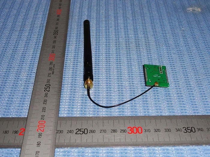
WMUHAC-LBEE
Feb 20, 2014Zigbee Module
Equipment Class
DTS - Digital Transmission System
WMUHAC-UBEEV3X
Apr 11, 2011Zigbee Module
Equipment Class
DTS - Digital Transmission System