WP3DISCMCWWIRELESS POWERCODE DIGITAL CEILING MOUNT PIR DETECTOR
Visonic Ltd.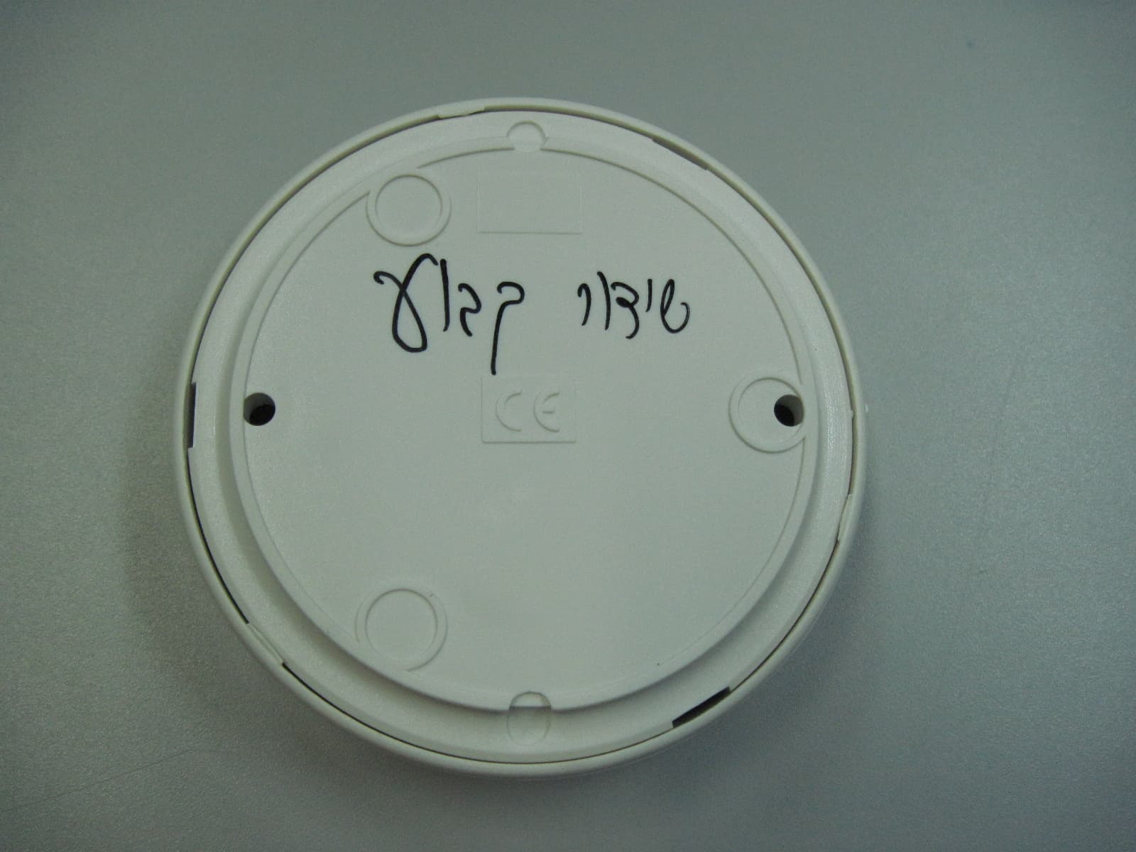
Click to zoom
Application Details
- Equipment Class
- DSC - Part 15 Security/Remote Control Transmitter
- Date of Grant
- Feb 14, 2011
- Application Purpose
- Original Equipment
- Date of Application
- Feb 13, 2011
- Equipment Note
- WIRELESS POWERCODE DIGITAL CEILING MOUNT PIR DETECTOR
- Frequency Range
- 315.00000000 - 315.00000000
- Company
- Visonic Ltd.
- Country
- Israel
Documents & Files
Document Text
Text extracted from the exhibit documents filed with the FCC. Open a document above to read the original.
Users Manual
D-302924 1 DISC MCW Wireless PowerCode Digital Ceiling Mount PIR detector Installation Instructions 1. INTRODUCTION The DISC MCW is the smallest 360° ceiling mounted passive infrared detector presently marketed. The DISC MCW is a microprocessor-controlled wireless digital PIR detector, designed for easy installation. The DISC MCW provides a nearly conical pattern of maximum 10.5 m (36 ft) diameter, when installed on a 3.6 m (12ft) ceiling. The advanced True Motion Recognition™ algorithm (patented) allows to distinguish between the true motion of an intruder and any other disturbances which may cause false alarms. False alarms caused by environmental disturbances are virtually eliminated with alternate polarity pulse counter signal processin g and a low-noise pyroelectric detector. The DISC MCW includes the following features: • Provides multiple beams coverage. • Incorporates a fully supervised PowerCode transmitter. • Sophisticated frequency domain digital signal processing. • Programmable motion event counter. • Very low current consumption • Tamper switch for detector opening. • White light protection. • Elegantly styled, sturdy case. Figure 1 – External View 2. SPECIFICATIONS Detector Type: Dual element low-noise pyroelectric sensor. ELECTRICAL Internal Battery: 3V Lithium battery, type CR-123A. For UL installations, use Panasonic, Sanyo or GP only. Nominal Battery Capacity: 1400 mA/h. Battery Life (with LED on): Typically over 3 years. Battery Power Test: Performed immediately upon battery insertion and periodically after every several hours. FUNCTIONAL True Motion Event Verification: 2 position selector - 1 (OFF) or 2 (ON) motion events. Visual Indications: LED Lights for about 3 seconds upon transmission of alarm & tamper messages and upon motion detection in the walk test mode. LED Flashes during the power-up stabilization period, or after restoring (pressing) the tamper switch. LED does not light upon transmission of supervision messages. Rearm Timer: Rearms the detector 2 minutes after the last motion detection. The detector reverts to the initial state if there is no movement during 2 minutes. The timer is disabled in the walk test mode. WIRELESS Frequency (MHz): 315 (U.S. version) or other frequency according to local requirements. Transmission Sequence: 3 data bursts at variable / random intervals within 3 seconds. Encoding: Over 16 million possible combinations. Total Message Length: 36 bits. Supervision Message: Signaling at 60-minute intervals (U.S. version). MOUNTING Ceiling Mounting: Maximum mounting height 3.6 m (12 ft) ENVIRONMENTAL RFI Protection: >10 V/m up to 2000 MHz. Operating Temperatures: -10 °C to 50°C (14°F to 122°F). Storage Temperatures: -20 °C to 60°C (-4°F to 140°F). Compliance with Standards: Designed to meet FCC Part 15. PHYSICAL Dimensions (diam. x H) : 86 x 24 mm (3-3/8 x 15/16 in). Weight: 64 grams (2 oz) Color: White . PATENTS U.S. Patents 5,693,943 z 6,818,881 (other patents pending). Figure 2 - DISC MCW PIR Coverage Pattern 2 D-302924 3. INSTALLATION 3.1 Mounting The DISC MCW PIR is installed on the ceiling. The maximum installation height is 3.6m (12 ft). A. Mount the unit so that the expected motion of an intruder is perpendicular to the detector and not into the detector. Be sure to install the detector on a stable ceiling, to avoid vibrations. Note: Passive infrared detectors are sensitive to changes in infrared energy caused by an object moving across the unit's field of view. Detection of changes in infrared energy depends on the amount of infrared energy transmitted by the moving object, and the temperature difference between the object and the background. Because of this the PIR may fail to respond under certain temperature and background conditions, in which the temperature difference is too small. B. The DISC MCW is extremely immune to air turbulence and RFl interference. However, to minimize possible false alarms, it is highly recommended that you avoid aiming the detector at heaters, sources of light, or windows subjected to direct sunlight. Avoid mounting the DISC MCW in locations where air drafts could flow from the ceiling or from close walls. Also avoid running wiring close to high power electrical cables. COVER BASE Figure 3 - Removing the Cover C. Hold the unit base as shown in Figure 3. Rotate the cover counter clockwise until it stops. Separate the cover from the base. Note: If the cover does not separate easily from the base, insert a 1/8" screwdriver between a tab (on the cover) and a slot (on the base). Lower the screwdriver handle until the base separates from the cover and removes easily. D. Mount the base (equipped with the printed circuit board) in the location selected for optimum coverage. Using the two mounting holes at the back of the base fasten the unit firmly to the mounting surface to avoid possible vibrations. (Figure 4). Line up the 3 tabs on the cover with the 3 slots on the base. Fit the cover over the base. Rotate the cover clockwise until it stops. Figure 4 – Installing the Cover 3.2 LED Functions After battery insertion and rear cover closure, the LED flashes for 2 minutes approximately until the detector stabilizes. After stabilization, the detector enters automatically walk-test period of 15 minutes (see section 3.6 Walk Test below). In this mode the LED lights and the unit sends an RF alarm signal on every detection (regardless of LED jumper position). After the walk-test period, the LED operates according to the LED jumper setting, as follows: LED Jumper Position LED Activity in "Normal Mode" ON LED lights during alarm transmission. OFF LED does not light during alarm transmission. After the first 15 minutes, following every motion detection and alert transmission, the detector disarms itself to save battery power. It rearms (reverts to the ready state) if there is no subsequent detection during the following 2-minute period. Therefore, if you want to check the detector, you have to exit the room for a…
Text truncated - open the document above for the full version.
Cover Letter(s)
08 February 2011 To: Timco Engineering Inc. To Whom It May Concern We hereby authorize Shaike Raz of ITL to act on the behalf of Visonic Ltd, regarding the FCC ID Certification process for the following application FCC ID: WP3DISCMCW Thank you, Arick Elshtein
Cover Letter(s)
08 February 2011 Letter of individual Authorization to sign Form 731 To: Timco Engineering Inc. To Whom It May Concern We hereby authorize Shaike Raz of ITL as an authorized individual to sign for form 731 on behalf of Visonic Ltd for the FCC ID: WP3DISCMCW application. Thank you, Arick Elshtein
Cover Letter(s)
Date: 08 February 2011 Federal Communications Commission Authorization and Evaluation Division Subject: Confidentiality Request regarding application for certification of FCC ID: WP3DISCMCW Dear Sirs Pursuant to Sections 0.457 and 0.459 of the Commission’s Rules, we hereby request confidential treatment of information accompanying this application as outlined below: CONF APPENDIX DISC MCW Schem.pdf CONF APPENDIX DISC MCW PartsLst.pdf CONF APPENDIX DISC MCW BlkDia.pdf The above materials contain trade secrets and proprietary information not customarily released to the public. The public disclosure of these materials may be harmful to the applicant and provide unjustified benefits to its competitors. The applicant understands that pursuant to Section 0.457 of the Rules, disclosure of this application and all accompanying documentation will not be made before the date of the Grant for this application. Sincerely, Arick Elshtein
ID Label/Location Info
Label location
Operational Description
Operational description DISC MCW (315) The DISC MCW (315) is the smallest 360 deg ceiling mounted passive infrared detector presently marketed. The DISC MCW is a microprocessor- controlled wireless digital PIR detector, designed for easy installation. The DISC MCW provides a nearly conical pattern of maximum 10.5m (36ft) diameter, when installed on 3.5m(12ft) ceiling. The advanced True Motion Recognition TM algorithm (patented) allows to distinguish between the true motion of an intruder and any other disturbances which may cause false alarms. False alarms caused by environmental disturbances are virtually eliminated with alternate polarity pulse counter signal processing and low-noise pyroelectric detector.
Parts List/Tune Up Info
Date: 08 February 2011 To Whom It May Concern I hereby declare that there is no tune-up procedure for: FCC ID: WP3DISCMCW Thank you, Arick Elshtein
Test Report
DATE: 01 February 2011 I.T.L. (PRODUCT TESTING) LTD. FCC Radio Test Report for Visonic Ltd. Equipment under test: Wireless PowerCode Digital Ceiling Mount PIR Detector Disc MCW (315) Written by: ___________________________ D. Shidlowsky, Documentation Approved by: _____________________________ A. Sharabi, Test Engineer Approved by: _____________________________ I. Raz, EMC Laboratory Manager This report must not be reproduced, except in full, without the written permission of I.T.L. (Product Testing) Ltd. This report relates only to items tested. Test Report E104891.00 Visonic Ltd. Page 1 of 37 FCC ACC M Ver 1.1 05Mayl 2000 Test Report E104891.00 Visonic Ltd. Page 2 of 37 FCC ACC M Ver 1.1 05Mayl 2000 Measurement/Technical Report for Visonic Ltd. Wireless PowerCode Digital Ceiling Mount PIR Detector Disc MCW (315) FCC ID: WP3DISCMCW IC:1457C-DISCMCW This report concerns: Original Grant: x Class I change: Class II change: Equipment type: Part 15 Security/Remote Control Transceiver 47CFR15 Section 15231 (a-d) Measurement procedure used is ANSI C63.4-2003. Application for Certification Applicant for this device: prepared by: (different from "prepared by") Ishaihou Raz Arik Elshtein ITL (Product Testing) Ltd. Visonic Ltd. Kfar Bin Nun 24 Habarzel St. D.N. Shimshon 99780 Tel-Aviv 69710 Israel Israel e-mail [email protected] Tel: +972-3 -645-6789 Fax: +972-3-645-6788 e-mail: [email protected] TABLE OF CONTENTS 1. GENERAL INFORMATION--------------------------------------------------------------------------------4 1.1 Administrative Information ................................................................................ 4 1.2 List of Accreditations ........................................................................................ 5 1.3 Product Description .......................................................................................... 6 1.4 Test Methodology ............................................................................................. 6 1.5 Test Facility ....................................................................................................... 6 1.6 Measurement Uncertainty ................................................................................ 6 2. SYSTEM TEST CONFIGURATION ---------------------------------------------------------------------7 2.1 Justification ....................................................................................................... 7 2.2 Special Accessories ......................................................................................... 7 2.3 Equipment Modifications .................................................................................. 7 2.4 Configuration of Tested System ....................................................................... 7 3. RADIATED MEASUREMENT TEST SET-UP PHOTO ---------------------------------------------8 4. AVERAGE FACTOR CALCULATION ------------------------------------------------------------------9 4.1 Test Instrumentation Used ............................................................................. 11 5. PERIODIC OPERATION --------------------------------------------------------------------------------- 12 5.1 Specification ................................................................................................... 12 5.2 Requirements ................................................................................................. 12 5.3 Results ............................................................................................................ 12 6. FIELD STRENGTH OF FUNDAMENTAL ----------------------------------------------------------- 16 6.1 Test Specification ........................................................................................... 16 6.2 Test Procedure ............................................................................................... 16 6.3 Measured Data ............................................................................................... 16 6.4 Test Instrumentation Used, Field Strength of Fundamental ........................... 20 7. RADIATED EMISSION, 9 KHZ – 30 MHZ ----------------------------------------------------------- 21 7.1 Test Specification ........................................................................................... 21 7.2 Test Procedure ............................................................................................... 21 7.3 Measured Data ............................................................................................... 21 7.4 Test Instrumentation Used, Radiated Measurements .................................... 22 7.5 Field Strength Calculation .............................................................................. 22 8. SPURIOUS RADIATED EMISSION ------------------------------------------------------------------- 23 8.1 Test Specification ........................................................................................... 23 8.2 Test Procedure ............................................................................................... 23 8.3 Test Data ........................................................................................................ 24 8.4 Test Instrumentation Used, Radiated Measurements .................................... 26 9. BANDWIDTH ------------------------------------------------------------------------------------------------ 27 9.1 Test procedure ............................................................................................... 27 9.2 Results table ................................................................................................... 28 9.3 Test Equipment Used. .................................................................................... 29 10. 11. APPENDIX A - CORRECTION FACTORS ----------------------------------------------------- 30 10.1 Correction factors for CABLE ........................................................................ 30 10.2 Correct…
Text truncated - open the document above for the full version.
Contact Information
Applicant
Zuri Rubin(Certification Manager)
Test Firm
Israel Testing LaboratoriesIIan Cohen
Technical Specifications
| # | Rule Parts | Frequency Range | Power Output |
|---|---|---|---|
| 1 | 15.231 | 315 MHz - 315 MHz | - |
Other Applications from Visonic Ltd.
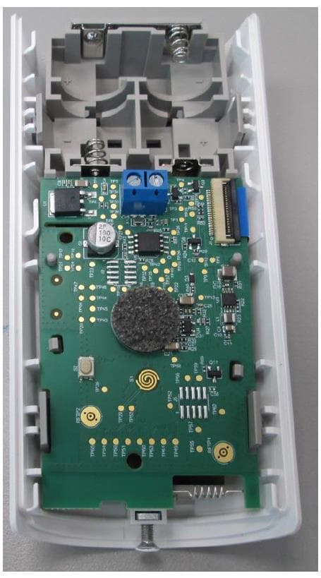
WP3NEXTCAMPGP
Dec 21, 2023Wireless Motion detector with integrated camera
Equipment Class
DSS - Part 15 Spread Spectrum Transmitter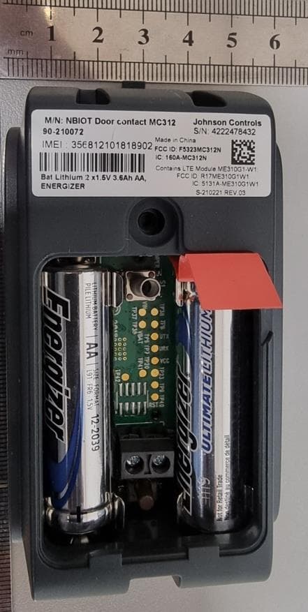
WP3RP600PGP
May 16, 2023Wireless Repeater for PowerG Communications
Equipment Class
DSS - Part 15 Spread Spectrum Transmitter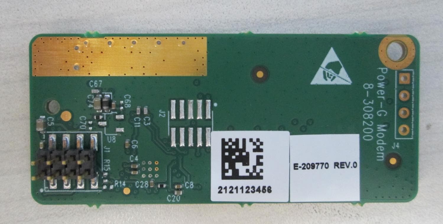
WP3PGMODIQREM
Jun 02, 2021Power-G Modem iQ Remote
Equipment Class
DSS - Part 15 Spread Spectrum Transmitter
WP3SD304EPG2
Jan 03, 2021PowerG Wireless Shock Detector
Equipment Class
DSS - Part 15 Spread Spectrum Transmitter
WP3MP843
Jun 30, 2020PIR detector ZigBee
Equipment Class
DTS - Digital Transmission System