WP3PGMODIQREMPower-G Modem iQ Remote
Visonic Ltd.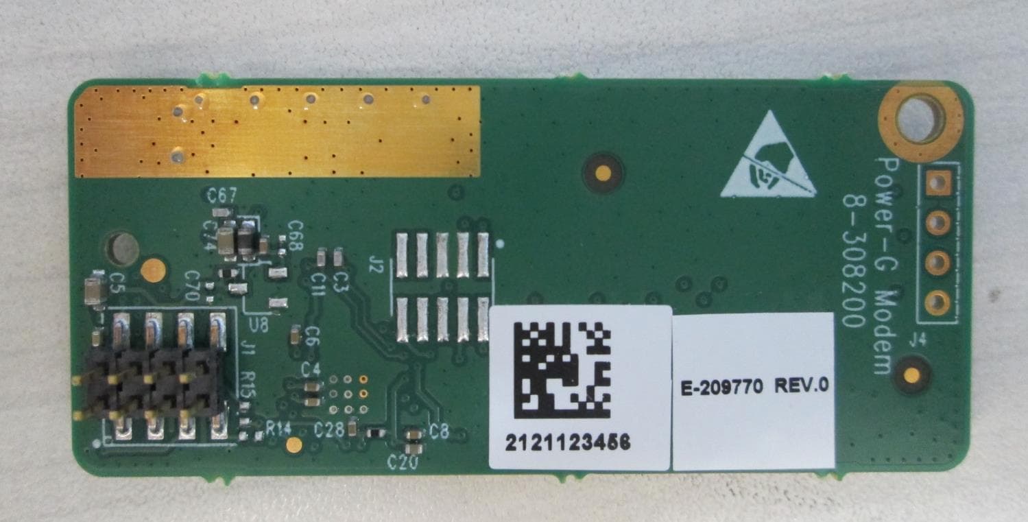
Click to zoom
Application Details
- Equipment Class
- DSS - Part 15 Spread Spectrum Transmitter
- Date of Grant
- Jun 02, 2021
- Application Purpose
- Original Equipment
- Date of Application
- Jun 02, 2021
- Equipment Note
- Power-G Modem iQ Remote
- Frequency Range
- 912.75000000 - 919.10600000
- Company
- Visonic Ltd.
- Country
- Israel
Documents & Files
Document Text
Text extracted from the exhibit documents filed with the FCC. Open a document above to read the original.
Users Manual
D-308486 POWER-G Modem iQ Remote Installation instructions 1 Installation Instructions POWER-G Modem iQ Remote High Efficient Wireless Transceiver Module 1. INTRODUCTION The Power-G Modem iQ Remote low power consumption module is a wireless transceiver designed for providing simple access to wireless devices. Its main application is an RF interface in a security system that communicates Power-G messages. The transceiver features UART ports that can communicate to the host of the control panel. Mechanical support and electrical connections are obtained by mounting the modem on an 8-pin connector and fastening it with a screw to the panel main board. 2. SPECIFICATIONS Frequency band: USA: 912-919 MHz Bandwidth: 118 kHz Data rate: 50 Kb/s Communication interface: UART Antenna input: Coaxial connector U. FL-R-SMT-1(60) – Herose Supply voltage: 3.3V +/-5% Transmit current consumption: 35mA Receiver current consumption: 8mA Operating temperature: -10 + 55 °C Dimensions: 57x25x7mm 3. INSTALLATION Figure 1 Callout Description 1 Antenna connector U. FL-R-SMT-1(60) – HEROSE 2 J1 connector 3 Support screw 4 25.0 mm 5 57.0 mm Function: J1 connector 1. VCC – Operating voltage: Nominal voltage: 3.3V 2. UART_Rx – Serial asynchronous UART receive port 3. UART_Tx – Serial asynchronyous UART transmit port 4. GND 5. RST – low level active 6. SYSTEM_INT – output, low level active, BOOT0 – input, low level active 7. Not used 8. Not used 4. COMPLIANCE WITH STANDARDS USA: FCC 47CFR Part 15 Canada: IC RSS-247 Visonic Ltd. M/N: Power-G Modem iQ Remote FCC ID: WP3PGMODIQREM IC: 1467C- PGMODIQREM OEM Integration Notices This device is intended only for OEM integrators under the following conditions: 1) The antenna must be installed such that 20 cm is maintained between the antenna and users, and 2) The transmitter module may not be co-located with any other transmitter or antenna. As long as 2 conditions above are met, further transmitter test will not be required. However, the OEM integrator is still responsible for testing their end-product for any additional compliance requirements required with this module installed. IMPORTANT NOTE: In the event that these conditions cannot be met (for example certain laptop configurations or co-location with another transmitter), then the FCC authorization is no longer considered valid and the FCC ID cannot be used on the final product. In these circumstances, the OEM integrator will be responsible for re- evaluating the end product (including the transmitter) and obtaining a separate FCC or authorization. End Product Labeling This transceiver module is only authorized for use in the device when the antenna is installed and maintained at a distance of 20 cm from the user (for example: wireless AP, wireless Router). The final end product must be labeled in a visible area with the following: “Contains TX FCC ID: PGMODIQREM; IC: 1467C-PGMODIQREM”. OEM Manual Information The OEM integrator must not provide information regarding installing or removing this RF module in the end product user manual which integrates this module. The OEM integrator user manual must include the following information in a prominent location: “IMPORTANT NOTE: To comply with FCC RF exposure compliance requirements, the antenna used for this transmitter must be installed to provide a separation distance of at least 20 cm from all persons and must not be co-located or operating in conjunction with any other antenna or transmitter." To comply with FCC and IC RF exposure compliance requirements, the device should be located at a distance of at least 20 cm from all persons during normal operation. The antennas used for this product must not be co-located or operated in conjunction with any other antenna or transmitter. Le dispositif doit être placé à une distance d'au moins 20 cm à partir de toutes les personnes au cours de son fonctionnement normal. Les antennes utilisées pour ce produit ne doivent pas être situés ou exploités conjointement avec une autre antenne ou transmetteur. This device complies with Part 15 of the FCC Rules and RSS-247 of ISED. Operation is subject to the following two conditions: (1) This device may not cause harmful interference, and (2) this device must accept any interference received, including interference that may cause undesired operation. Le présent appareil est conforme aux CNR d’ISED applicables aux appareils radio exempts de licence. L’exploitation est autorisée aux deux conditions suivantes : (1) l’appareil ne doit pas produire de brouillage, et (2) l’utilisateur de l’appareil doit accepter tout brouillage radioélectrique subi, même si le brouillage est susceptible d’en compromettre le fonctionnement. 2 D-308486 POWER-G Modem iQ Remote Installation instructions NOTE: This equipment has been tested and found to comply with the limits for a Class B digital device, pursuant to part 15 of the FCC Rules. These limits are designed to provide reasonable protection against harmful interference in a residential installation. This equipment generates, uses and can radiate radio frequency energy and, if not installed and used in accordance with the instructions, may cause harmful interference to radio communications. However, there is no guarantee that interference will not occur in a particular installation. If this equipment does cause harmful interference to radio or television reception, which can be determined by turning the equipment off and on, the user is encouraged to try to correct the interference by one or more of the following measures: – Reorient or relocate the receiving antenna. – Increase the separation between the equipment and receiver. – Connect the equipment into an outlet on a circuit different from that to which the receiver is connected. – Consult the dealer or an experienced radio/TV technician for help. This class B digital apparatus complies with Canadian ICES-003. Cet appareil numerique de la classe B est conforme a la norme NMB- 003 du Canada. WARNING! Cha…
Text truncated - open the document above for the full version.
Cover Letter(s)
Visonic Ltd. 24 Habarzel Street P.O.Box 22020 Tel-Aviv 69710, Israel Tele: +972 3 645 6789 Fax: +972 3 645 6788 www.visonic.com Declaration of Authorization We Name: Visonic Ltd. Address: 24 Habarzel street City: Tel Aviv 69710 Country: Israel Declare that: Name Representative of agent: ............. (1) Agent Company name: Hermon Laboratories Ltd. Address: Harakevet Industrial Zone City: Binyamina 3055001 Country Israel is authorized to apply for Certification of the following product(s): Product description: Power-G Modem iQ Remote Type designation: PG Modem iQ Remote Trademark: Visonic Validity/ expiry date: May 23, 2022 on our behalf. Date: May 23, 2021 City: Tel Aviv Name: Zuri Rubin (2) Function: Certification Manager Signature: Notes: (1): Required for FCC application (2): For FCC it must be the Grantee Code “owner” or the authorized agent.
Cover Letter(s)
RF_734_02 04 April 16 Modular Approval Request FCC (KDB 996369 D01 & Part 15.212) FCC ID: WP3PGMODIQREM Items to be covered by Single modular transmitters. Answer from applicant 1.The modular transmitter must have its own RF shielding.The modular transmitter has its own RF shielding. The RF shielding cover consists of tin preplaced steel sheet 2. The modular transmitter must have buffered modulation/data inputs (if such inputs are provided) to ensure that the module will comply with Part 15 requirements under conditions of excessive data rates or over-modulation. There is no modulation/data input from the host to the RF module 3.The modular transmitter must have its own power supply regulation.All RF parts are regulated with on board IC LDO 4. The modular transmitter must comply with the antenna requirements of Section 15.203 and 15.204(b)(c). The antenna must either be permanently attached or employ a “unique” antenna coupler (at all connections between the module and the antenna, including the cable). Antenna in use is monopole or inverted F ISM antenna, which connected to on board coaxial connector 5. The modular transmitter must be tested in a stand-alone configuration, i.e., the module must not be inside another device during testing. This is intended to demonstrate that the module is capable of complying with Part 15 emission limits regardless of the device into which it is eventually installed. The Tx module was tested in stand –alone configuration connected with 15 sm. cable to evaluation board 6. The modular transmitter must be equipped with either a permanently affixed label or must be capable of electronically displaying its FCC identification number in accordance with 15.212 (a)(1)(vi)(A) / (B). The modular transmitter has its own FCC ID number. The FCC ID is not visible, when the module is installed inside another device, a user has the instructions to apply the FCC ID: WP3PGMODEMLP label on the other device. Refer to “User_manual_42668” 7. The modular transmitter must comply with any specific rule or operating requirements applicable to the transmitter and the manufacturer must provide adequate instructions along with the module to explain any such requirements. A copy of these instructions must be included in the application for equipment authorization. For example, there are very strict operational and timing requirements that must be met before a transmitter is authorized for operation under Section 15.231. For instance, data transmission is prohibited, except for operation under Section 15.231(e), in which case there are separate field strength level and timing requirements. Compliance with these requirements must be assured. There is no specific rule or operating requirements applicable to the transmitter with respect to user operation 8. The modular transmitter must comply with any applicable RF exposure requirements. For example, FCC Rules in Sections 1.1310, 2.1091, 2.1093, and specific Sections of Part 15, including 15.319(i), 15.407(f), 15.253(f) and 15.255(g), require that Unlicensed PCS, UNII and millimeter wave devices perform routine environmental evaluation for RF Exposure to demonstrate compliance. In addition, spread spectrum transmitters operating under Section 15.247 are required to address RF Exposure compliance. Modular transmitters approved under other Sections of Part 15, when necessary, may also need to address certain RF Exposure concerns, typically by providing specific installation and operating instructions for users, installers and other interested parties to ensure compliance. The modular transmitter complies with any applicable RF exposure requirements as specified in FCC part 15 section 15.247 and section 1.1310 Name and surname of applicant (or authorized representative): Zuri Rubin Date: 19/05/2021Signature:
Cover Letter(s)
FCC, Request for non-disclosure Date: 21-Nov-2018 RF_501, Issue 8 Page 1 of 1 Company Name: Visonic Ltd. Address: Habarzel street 24 City: Tel Aviv 69710 Country: Israel To: Telefication B.V., Dept. FCC TCB Edisonstraat 12A 6902 PK ZEVENAAR The Netherlands Subject: Request for confidentiality FCC ID: WP3PGMODIQREM Reference number: 42668 Dear FCC TCB, 1. Long-Term Confidentiality Pursuant to 47 CFR Section 0.459(a) & (b), we hereby requests non-disclosure and confidential treatment of the following materials submitted in support of FCC certification application: Bill(s) of Material Block Diagrams Operational Description Schematic Diagrams Tune-up Procedure Above materials contain secrets, proprietary and technical information, which would customarily be guarded from competitors under 47 CFR, section 0.457(d)(2). Disclosure or publication or any portion of this company confidential material to other parties could cause substantial competitive harm and provide unjustified benefits for competitors. 2. Short-Term Confidentiality (STC) Pursuant to Public Notice DA 04-1705 of the Commission’s policy, in order to comply with the marketing regulations in 47 CFR §2.803 and the importation rules in 47 CFR §2.1204, applicant hereby requests Short-Term Confidential treatment of the following materials (See notes below): Internal Photos User’s Manual Test Set-up Photos External Photos Justification: in order to avoid exposed of the technology to the competitors Date: May 19, 2021 Name and signature of applicant: Mr. Zuri Rubin Notes: 1) A document or type of document can only have ONE type of confidentiality! 2) Short-Term confidentiality is in principle for 45 days from date of grant; it can be extended max 3 times (total time 180 days max.)! The planned date should stated in the RF731 application form. 3) FCC must be informed when marketing begins earlier. 4) Release takes place automatically thus extension must be requested in time. Telefication does not remind you of this! 5) Request for extension or for release must be received by Telefication at least 7 days before date of actual marketing or before expiration of the STC period
External Photos
Visonic Ltd. FCC ID:WP3PGMODIQREM IC:1467C-PGMODIQREM Page 1 of 4 EXTERNAL PHOTOGRAPHS This document contains 5 photographs Visonic Ltd. FCC ID:WP3PGMODIQREM IC:1467C-PGMODIQREM Page 2 of 4 Photograph No.1 PG Modem iQ Remote Front side Visonic Ltd. FCC ID:WP3PGMODIQREM IC:1467C-PGMODIQREM Page 3 of 4 Photograph No.2 PG Modem iQ Remote Back side
ID Label/Location Info
ECM Title: TYCO LABEL DRAWING 22783 22844 Product Name: Label PG Modem IQ- HUB V4 FCC (915M) Date Name Document No: 4017270 24.02.2021 ALBERT F Created Document Rev: 01 10.05.2021 ALBERT F. Updated Sheet 1 of 1 10.05.2021 SHAY A. Approved MATERIAL: Polyester S-0001-J SIZE: 23*22 mm
Internal Photos
Visonic Ltd. FCC ID:WP3PGMODIQREM IC:1467C-PGMODIQREM Page 1 of 4 INTERNAL PHOTOGRAPHS This document contains 5 photographs Visonic Ltd. FCC ID:WP3PGMODIQREM IC:1467C-PGMODIQREM Page 2 of 4 Photograph No.1 PG Modem iQ Remote Component side of the RF PCB Visonic Ltd. FCC ID:WP3PGMODIQREM IC:1467C-PGMODIQREM Page 3 of 4 Photograph No.2 PG Modem iQ Remote Print side of the RF PCB Visonic Ltd. FCC ID:WP3PGMODIQREM IC:1467C-PGMODIQREM Page 4 of 4 Photograph No.3 PG Modem iQ Remote Shielding compartments of the RF PCB
RF Exposure Info
Visonic Ltd. FCC ID:WP3PGMODIQREM IC: 1467C-PGMODIQREM Exposure limit according to §15.247(i) The PG Modem iQ Remote is classified as a mobile device. The FCC limit for power density for general population/uncontrolled exposure is f/1500 mW/cm 2 for 300 – 1500 MHz frequency range: P = 912.75/1500 = 0.61 mW/cm 2 The power density P (mW/cm 2 ) = P T / 4 r 2 P T is the transmitted power, which is equal to the peak transmitter output power 12.29 dBm plus maximum antenna gain 2 dBi, the maximum equivalent isotropically radiated power EIRP is P T = 12.29 dBm + 2 dBi = 14.29 dBm = 26.85 mW. The power density at 20 cm (minimum safe distance, required for mobile devices), calculated as follows: Compliance with FCC limit: 26.85 mW / 4 (20 cm) 2 = 0.0053 mW/cm 2 << 0.61 mW/cm 2 General public cannot be exposed to dangerous RF level.
Test Report
Hermon Laboratories Ltd. P.O. Box 23, Binyamina 3055001, Israel Tel. +972 4628 8001 Fax. +972 4628 8277 E-mail: [email protected] Page 1 of 45 ELECTRICAL TESTING 0839.01 TEST REPORT ACCORDING TO: FCC 47CFR part 15 subpart C §15.247 (FHSS) and subpart B, RSS-247 Issue 2:2017, RSS-Gen Issue 5:2019, ICES-003 Issue 6:2016 FOR: Visonic Ltd. Power-G Modem iQ Remote Model: PG Modem iQ Remote FCC ID: WP3PGMODIQREM IC: 1467C-PGMODIQREM This report is in conformity with ISO/ IEC 17025. The "A2LA Accredited" symbol endorsement applies only to the tests and calibrations that are listed in the scope of Hermon Laboratories accreditation. The test results relate only to the items tested. This test report shall not be reproduced in any form except in full with the written approval of Hermon Laboratories Ltd. Report ID: VISRAD_FCC.42668 Date of Issue: 11-May-21 Page 2 of 45 Table of contents 1 Applicant information ..................................................................................................................................................... 3 2 Equipment under test attributes .................................................................................................................................... 3 3 Manufacturer information .............................................................................................................................................. 3 4 Test details .................................................................................................................................................................... 3 5 Tests summary .............................................................................................................................................................. 4 6 EUT description ............................................................................................................................................................. 5 6.1 General information ....................................................................................................................................................... 5 6.2 Test configuration .......................................................................................................................................................... 5 6.3 Changes made in EUT .................................................................................................................................................. 5 6.4 Transmitter characteristics ............................................................................................................................................ 6 7 Transmitter tests according to 47CFR part 15 subpart C and RSS-247 requirements .................................................. 7 7.1 20 dB bandwidth ........................................................................................................................................................... 7 7.2 Carrier frequency separation ....................................................................................................................................... 10 7.3 Number of hopping frequencies .................................................................................................................................. 12 7.4 Average time of occupancy ......................................................................................................................................... 14 7.5 Peak output power ...................................................................................................................................................... 17 7.6 Field strength of spurious emissions ........................................................................................................................... 21 7.7 Antenna requirements ................................................................................................................................................. 32 8 Unintentional emissions .............................................................................................................................................. 33 8.1 Radiated emission measurements .............................................................................................................................. 33 9 APPENDIX A Test equipment and ancillaries used for tests ....................................................................................... 36 10 APPENDIX B Test equipment correction factors ......................................................................................................... 37 11 APPENDIX C Measurement uncertainties .................................................................................................................. 41 12 APPENDIX D Test laboratory description ................................................................................................................... 42 13 APPENDIX E Specification references........................................................................................................................ 43 14 APPENDIX F Manufacturer’s declaration of Identity ................................................................................................... 44 15 APPENDIX G Abbreviations and acronyms ................................................................................................................ 45 Report ID: VISRAD_FCC.42668 Date of Issue: 11-May-21 Page 3 of 45 1 Applicant information Client name: Visonic Ltd. Address: 24 Habarzel street, Tel Aviv 69710, Israel Telephone: +972 3645 6832 Fax: +972 3645 6788 E-mail: [email protected] Contact name: Mr. Zuri Rubin 2 Equipment under test attributes Product name: Power-G Modem iQ Remote Product type: Transceiver Model(s): PG Modem iQ Remote Serial number: NA Hardware version: E-209770 Software release: JS-703890 Receipt date 26-Apr-21 3 Manufacturer information Manufacturer name: Visonic Ltd. Address: 24 Habarz…
Text truncated - open the document above for the full version.
Test Setup Photos
Visonic Ltd. FCC ID:WP3PGMODIQREM IC: 1467C-PGMODIQREM Page 1 of 5 SETUP PHOTOGRAPHS This document contains 4 photographs Visonic Ltd. FCC ID:WP3PGMODIQREM IC: 1467C-PGMODIQREM Page 2 of 5 Photograph No.1 Setup for OBW measurements Visonic Ltd. FCC ID:WP3PGMODIQREM IC: 1467C-PGMODIQREM Page 3 of 5 Photograph No.2 Setup for band edge emission and hopping parameters measurements Visonic Ltd. FCC ID:WP3PGMODIQREM IC: 1467C-PGMODIQREM Page 4 of 5 Photograph No.4 Setup for carrier and spurious emissions measurements in anechoic chamber from 30 MHz to 1 GHz Visonic Ltd. FCC ID:WP3PGMODIQREM IC: 1467C-PGMODIQREM Page 5 of 5 Photograph No.5 Setup for field strength measurements in anechoic chamber above 1 GHz
Contact Information
Applicant
Zuri Rubin(Certification Manager)
Technical Contact
Hermon LaboratoriesMichael Nikishin
[email protected]97246268440
Harakevet Industrial zone, P.O.Box 23 · Binyamina · Israel
Non-Technical Contact
Visonic Ltd.Zuri Rubin
[email protected]97236456832
Test Firm
Hermon Laboratories Ltd.George Shleimovich
Technical Specifications
| # | Rule Parts | Frequency Range | Power Output |
|---|---|---|---|
| 1 | 15C | 912.75 MHz - 919.106 MHz | 17.00 mW |
Other Applications from Visonic Ltd.
WP3NEXTCAMPGP
Dec 21, 2023Wireless Motion detector with integrated camera
Equipment Class
DSS - Part 15 Spread Spectrum Transmitter
WP3RP600PGP
May 16, 2023Wireless Repeater for PowerG Communications
Equipment Class
DSS - Part 15 Spread Spectrum Transmitter
WP3SD304EPG2
Jan 03, 2021PowerG Wireless Shock Detector
Equipment Class
DSS - Part 15 Spread Spectrum Transmitter
WP3MP843
Jun 30, 2020PIR detector ZigBee
Equipment Class
DTS - Digital Transmission System
WP3MCT350SMA5
Dec 14, 2015Zigbee Door / Window Contact
Equipment Class
DTS - Digital Transmission System