WP3SD304EPG2PowerG Wireless Shock Detector
Visonic Ltd.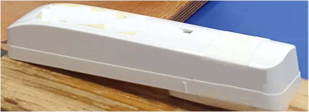
Click to zoom
Application Details
- Equipment Class
- DSS - Part 15 Spread Spectrum Transmitter
- Date of Grant
- Jan 03, 2021
- Application Purpose
- Original Equipment
- Date of Application
- Dec 27, 2020
- Equipment Note
- PowerG Wireless Shock Detector
- Frequency Range
- 912.75000000 - 919.10600000
- Company
- Visonic Ltd.
- Country
- Israel
Documents & Files
Document Text
Text extracted from the exhibit documents filed with the FCC. Open a document above to read the original.
Users Manual
D-306615SD-304CPG2InstallationInstructions1 Introducing SD-304C PG2 The SD-304C PG2 is a wireless PowerG innovative shock detector with optional magnetic contact and auxiliary input interfacing with all PowerMaster control panels, version 16 or higher. The SD-304C PG2 fits windows, doors, walls or roofs and is ideal for residential or commercial installations. It detects and analyzes gross attacks or a series of low level shocks and provides early warning of any intrusion attempt before a burglar actually breaks in. For the complete SD-304C PG2 Installer Guide, refer to D-304286 at http://www.visonic.com/download- center. Alternatively, contact us at [email protected] to request the complete version of the installation guide. 1. Mounting the Device Note:Use a manual screwdriver only. 1. Insert a flat-edged screwdriver into the slot and push upward to remove cover. 2. Remove screw. 3. Separate base from cover. 4. Secure the base to the mounting surface using only the screws supplied in the package. 5. Insert the battery while observing polarity. 6. Mount the magnet near its location mark with 2 screws. Caution!lDo not remove the PCB to mark holes but use the paper model included with the detector. lDo not use double-sided tape, as this will tend to insulate the detector from vibrations. Note:Once the cover is removed, the detector transmits a tamper message to the control panel. Subsequent removal of the battery prevents transmission of "TAMPER RESTORE", leaving the detector in permanent alert. To avoid this, press the tamper switch while you remove the battery. Caution!Risk of explosion if battery is replaced by an incorrect type. Dispose of used battery according to manufacturer's instructions. Attention!The unit has a back tamper switch (optional) under the PCB. As long as the PCB is seated firmly within the base, the switch lever will be pressed against a special break-away base segment that is loosely connected to the base.Be sure to fasten the break-away segment to the wall. 2. Auxiliary Input Wiring See the complete installation guide for details. 3. Enrollment of the Device Refer to the PowerMaster panel's Installer Guide. To enroll the device enter the Installation menu and do as follows: 1. From the Installation menu, select02:ZONES/DEVICESand clickOK. 2. SelectADD NEW DEVICESand clickOK. Panel displays: <ENROLL NOW or ENTER ID:xxx-xxxx> 3. EnterID:XXX-XXXX(the number of the device that is displayed on the label), Or press theEnrollbutton in the device. The display shows the device details and first available free Zone/Device number. For example: "Z01:Motion Sensor > ID No. 120-1234" or "K01:Keyfob / S01:Siren. The display depends on the type of enrolled device. 4. To change the Zone/Device number, click the arrow button or type the zone number and then clickOK. 5. To configure the location and zone type, selectZ14.LOCATIONand Z14.ZONE TYPEand select desired settings. 6. To assign partitions, press the1,2and3buttons and then clickOK. Note:To enter PARTITIONS, it must be enabled first. 7. Select one of the following options: lContinue to configure the device l Select and then clickOKto exit 4. Configuring the Detector Enter theDEVICE SETTINGSmenu in the PowerMaster and follow the configuration instructions for the SD-304C PG2 shock detector. You can calibrate the SD-304C PG2 locally only when the device is in Local Diagnostics mode (first 15 minutes after opening the cover). When the device is not in this mode but further calibration is required, reset the device by closing the tamper switch. 5. Calibrating the Detector You can calibrate the SD-304C PG2 locally only when the device is in Local Diagnostics mode (first 15 minutes after opening the cover). When the device is not in this mode but further calibration is required, reset the device by closing the tamper switch. See the complete installation guide for details. 6. Local Diagnostics Test Before testing, separate the base from the cover. LED responseReception Green LED blinksStrong Orange LED blinksGood Red LED blinksPoor No blinksNo communication Important!Reliable reception must be assured. Therefore, "poor" signal strength is not acceptable. If you receive a "poor" signal from the device, re- locate it and re-test until a "good" or "strong" signal strength is received. Note:For detailed Diagnostics Test instructions refer to the control panel Installer Guide. 7. Testing Procedures 1. Press the tamper switch once and release it. 2. Put back the cover to return the tamper switch to its normal (undisturbed) position, and then secure the front cover to the base with the case closure screw. 3. Use a hammer to apply shock in close proximity to the detector and verify the red LED blinks, indicating detection. 4. After 2 seconds the LED blinks 3 times. 8. Installation Tips lRefer to the Shock Detection Radius in the Specifications section, according to the surface material used. Install the device in a location where a strong shock impact is expected. Mount the unit on a flat surface and fix firmly using both mounting screws. lFor magnetic contact detection, it is highly recommended to attach the detector to the door/window on the fixed frame and the magnet to the movable part (door or window). Make sure that the magnet is located not more than 6 mm (0.25 in.) from the detector’s marked side. 9. Event Indications LED IndicationsEvent Red LED ON 0.2 sec.Tamper open / close Red ON 2 sec.Shock Red ON 2 sec.Open close door Red ON 2 sec.Open close Aux input Yellow LED ONAM detection – Diagnostic mode Yellow LED blinks slowly (0.2 sec. ON, 30 sec. OFF) AM detection – Normal mode 10. Compliance With Standards The SD-304C PG2 complies with the following standards: Europe:EN 301489, EN 50130-4, EN 300220, EN 60950-1, EN 50130-5, EN 50131-2-6, EN 50131-2-8, EN 50131-5-3, EN 50131-6. Hereby, Visonic Ltd. declares that the radio equipment type SD-304C PG2 is in compliance with Directive 2014/53/EU. The full text of the EU declaration of conf…
Text truncated - open the document above for the full version.
Cover Letter(s)
Visonic Ltd. 24 Habarzel Street P.O.Box 22020 Tel-Aviv 69710, Israel Tele: +972 3 645 6789 Fax: +972 3 645 6788 www.visonic.com December 16, 2020 Telefication B.V. Attn: Dept. FCC TCB Wilmersdorf 50 7327 AC Apeldoorn The Netherlands Subject: Application for certification of a PowerG Wireless Shock Detector, FCC ID:WP3SD304EPG2 Dear Gentlemen, Please find attached our application for certification of the PowerG Wireless Shock Detector, FCC ID: WP3SD304EPG2, prepared in accordance with FCC Rules, parts 2 and 15, section 15.247(FHSS). The product testing and this application for certification were performed by Hermon Laboratories, which is recognized and accredited by FCC, Test Firm Registration Number is 927748. Designation Number is IL1001. Hermon Labs responsible person is Mr. Michael Nikishin, Tel: +972 4626 8440, fax: +972 4628 8277, e-mail: [email protected]. We hope this application satisfies your requirements. Please send an invoice to Hermon Labs. Zuri Rubin, I Certification Manager Visonic Ltd.
Cover Letter(s)
Visonic Ltd. 24 Habarzel Street P.O.Box 22020 Tel-Aviv 69710, Israel Tele: +972 3 645 6789 Fax: +972 3 645 6788 www.visonic.com Declaration of Authorization We Name: Visonic Ltd. Address: 24 Habarzel street City: Tel Aviv 61920 Country: Israel Declare that: Name Representative of agent: ............. (1) Agent Company name: Hermon Laboratories Ltd. Address: Harakevet Industrial Zone City: Binyamina 30500 Country Israel is authorized to apply for Certification of the following product(s): Product description: PowerG Wireless Shock Detector Type designation: SD-304C PG2 FCC Trademark: Tyco Validity/ expiry date: December 16, 2021 on our behalf. Date: December 16, 2020 City: Tel Aviv Name: Zuri Rubin Function: Certification Manager Signature: Notes: (1): Required for FCC application (2): For FCC it must be the Grantee Code “owner” or the authorized agent.
Cover Letter(s)
FCC, Request for non-disclosure Date: 21-Nov-2018 RF_501, Issue 8 Page 1 of 1 Company Name: Visonic Ltd. Address: Habarzel street 24 City: Tel Aviv 61920 Country: Israel To: Telefication B.V., Dept. FCC TCB Wilmersdorf 50 7327 AC Apeldoorn The Netherlands Subject: Request for confidentiality FCC ID: WP3SD304EPG2 Reference number: ###### Dear FCC TCB, 1. Long-Term Confidentiality Pursuant to 47 CFR Section 0.459(a) & (b), we hereby requests non-disclosure and confidential treatment of the following materials submitted in support of FCC certification application: Bill(s) of Material Block Diagrams Operational Description Schematic Diagrams Tune-up Procedure Above materials contain secrets, proprietary and technical information, which would customarily be guarded from competitors under 47 CFR, section 0.457(d)(2). Disclosure or publication or any portion of this company confidential material to other parties could cause substantial competitive harm and provide unjustified benefits for competitors. 2. Short-Term Confidentiality (STC) Pursuant to Public Notice DA 04-1705 of the Commission’s policy, in order to comply with the marketing regulations in 47 CFR §2.803 and the importation rules in 47 CFR §2.1204, applicant hereby requests Short-Term Confidential treatment of the following materials (See notes below): Internal Photos User’s Manual Test Set-up Photos External Photos Justification: in order to avoid exposed of the technology to the competitors Date: December 16, 2020 Name and signature of applicant: Zuri Rubin Notes: 1) A document or type of document can only have ONE type of confidentiality! 2) Short-Term confidentiality is in principle for 45 days from date of grant; it can be extended max 3 times (total time 180 days max.)! The planned date should stated in the RF731 application form. 3) FCC must be informed when marketing begins earlier. 4) Release takes place automatically thus extension must be requested in time. Telefication does not remind you of this! 5) Request for extension or for release must be received by Telefication at least 7 days before date of actual marketing or before expiration of the STC period
External Photos
Visonic Ltd. FCC ID:WP3SD304EPG2 IC:1467C-SD304EPG2 Page 1 of 4 EXTERNAL PHOTOGRAPHS This document contains 3 photographs Visonic Ltd. FCC ID:WP3SD304EPG2 IC:1467C-SD304EPG2 Page 2 of 4 Photograph No.1 Shock detector “SD-304CPG2 FCC” general view Visonic Ltd. FCC ID:WP3SD304EPG2 IC:1467C-SD304EPG2 Page 3 of 4 Photograph No.2 Shock detector “SD-304CPG2 FCC” front view Visonic Ltd. FCC ID:WP3SD304EPG2 IC:1467C-SD304EPG2 Page 4 of 4 Photograph No.3 Shock detector rear side view
ID Label/Location Info
ECM Title: TYCO LABEL DRAWING 16320 19462 Product Name: LABEL SD-304C PG2 FCC Date Name 20690 Document No: 4011803 06.03.13 Yana K. Created TBD Document Rev: 03 16.12.2020 Albert F. Updated Sheet 1 of 1 16.12.2020 Shay A. Approved Label location MATERIAL: Polyester S-0001-B SIZE: 25.4*12.7 mm
Internal Photos
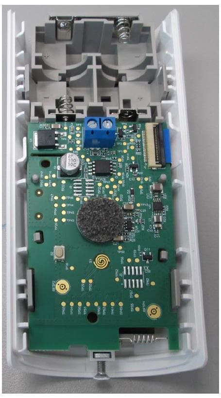
Visonic Ltd. FCC ID:WP3SD304EPG2 IC:1467C-SD304EPG2 Page 1 of 7 INTERNAL PHOTOGRAPHS This document contains 6 photographs Visonic Ltd. FCC ID:WP3SD304EPG2 IC:1467C-SD304EPG2 Page 2 of 7 Photograph No.1 Shock detector “SD-304CPG2 FCC” internal view Visonic Ltd. FCC ID:WP3SD304EPG2 IC:1467C-SD304EPG2 Page 3 of 7 Photograph No.2 Shock detector main PCB with RF card front view Visonic Ltd. FCC ID:WP3SD304EPG2 IC:1467C-SD304EPG2 Page 4 of 7 Photograph No.3 Shock detector main PCB with RF card rear side view Visonic Ltd. FCC ID:WP3SD304EPG2 IC:1467C-SD304EPG2 Page 5 of 7 Photograph No.4 Shock detector RF card with antenna close view Visonic Ltd. FCC ID:WP3SD304EPG2 IC:1467C-SD304EPG2 Page 6 of 7 Photograph No.5 Shock detector RF card front view Visonic Ltd. FCC ID:WP3SD304EPG2 IC:1467C-SD304EPG2 Page 7 of 7 Photograph No.6 Shock detector RF card rear side view
Test Report
Hermon Laboratories Ltd. P.O. Box 23, Binyamina 3055001, Israel Tel. +972 4628 8001 Fax. +972 4628 8277 E-mail: [email protected] Page 1 of 57 Report ID: VISRAD_FCC.40807.docx Date of Issue: 16-Dec-20 ELECTRICAL TESTING 0839.01 TEST REPORT ACCORDING TO: FCC 47CFR part 15 subpart C § 15.247 (FHSS) and subpart B, RSS-247 issue 2, RSS-Gen issue 5, ICES-003 Issue 6 FOR: Visonic Ltd. PowerG Wireless Shock Detector Model: SD-304C PG2 FCC FCC ID:WP3SD304EPG2 IC:1467C-SD304EPG2 This report is in conformity with ISO/ IEC 17025. The "A2LA Accredited" symbol endorsement applies only to the tests and calibrations that are listed in the scope of Hermon Laboratories accreditation. The test results relate only to the items tested. This test report shall not be reproduced in any form except in full with the written approval of Hermon Laboratories Ltd. Report ID: VISRAD_FCC.40807.docx Date of Issue: 16-Dec-20 Page 2 of 57 Table of contents 1 Applicant information ..................................................................................................................................................... 3 2 Equipment under test attributes .................................................................................................................................... 3 3 Manufacturer information .............................................................................................................................................. 3 4 Test details .................................................................................................................................................................... 3 5 Tests summary .............................................................................................................................................................. 4 6 EUT description ............................................................................................................................................................. 5 6.1 General information ....................................................................................................................................................... 5 6.2 Test configuration .......................................................................................................................................................... 5 6.3 Changes made in the EUT ............................................................................................................................................ 5 6.4 Transmitter characteristics ............................................................................................................................................ 6 7 Transmitter tests according to 47CFR part 15 subpart C and RSS-247 requirements .................................................. 7 7.1 20 dB bandwidth ........................................................................................................................................................... 7 7.2 Carrier frequency separation ....................................................................................................................................... 11 7.3 Number of hopping frequencies .................................................................................................................................. 14 7.4 Average time of occupancy ......................................................................................................................................... 17 7.5 Peak output power ...................................................................................................................................................... 20 7.6 Field strength of spurious emissions ........................................................................................................................... 25 7.7 Band edge radiated emissions .................................................................................................................................... 41 7.8 Antenna requirements ................................................................................................................................................. 45 8 Unintentional emissions .............................................................................................................................................. 46 8.1 Radiated emission measurements .............................................................................................................................. 46 9 APPENDIX A Test equipment and ancillaries used for tests ....................................................................................... 51 10 APPENDIX B Measurement uncertainties ................................................................................................................... 52 11 APPENDIX C Test laboratory description ................................................................................................................... 53 12 APPENDIX D Specification references ....................................................................................................................... 53 13 APPENDIX E Test equipment correction factors ......................................................................................................... 54 14 APPENDIX F Abbreviations and acronyms ................................................................................................................. 57 Report ID: VISRAD_FCC.40807.docx Date of Issue: 16-Dec-20 Page 3 of 57 1 Applicant information Client name: Visonic Ltd. Address: Habarzel street 24, Tel Aviv 61920, Israel Telephone: +972 3645 6832 Fax: +972 3645 6788 E-mail: [email protected] Contact name: Mr. Zuri Rubin 2 Equipment under test attributes Product name: PowerG Wireless Shock Detector Product type: Transceiver Model(s): SD-304C PG2 FCC Serial number: NA Hardware version: 90-205091 Software release: JS-703892 Receipt date 28-Oct-20 3 Man…
Text truncated - open the document above for the full version.
Test Setup Photos
Visonic Ltd. FCC ID:WP3SD304EPG2 IC:1467C-SD304EPG2 Page 1 of 8 SETUP PHOTOGRAPHS This document contains 7 photographs Visonic Ltd. FCC ID:WP3SD304EPG2 IC:1467C-SD304EPG2 Page 2 of 8 Photograph No.1 Setup for spurious emission field strength measurements in the anechoic chamber below 30 MHz Visonic Ltd. FCC ID:WP3SD304EPG2 IC:1467C-SD304EPG2 Page 3 of 8 Photograph No.2 Setup for carrier field strength, OBW, spurious emission field strength measurements in the anechoic chamber in 30 – 1000 MHz range Visonic Ltd. FCC ID:WP3SD304EPG2 IC:1467C-SD304EPG2 Page 4 of 8 Photograph No.3 Setup for carrier field strength, OBW, spurious emission field strength measurements in the anechoic chamber below 1000 MHz, EUT close view Visonic Ltd. FCC ID:WP3SD304EPG2 IC:1467C-SD304EPG2 Page 5 of 8 Photograph No.4 Setup for spurious emission field strength measurements in the anechoic chamber above 1000 MHz range Visonic Ltd. FCC ID:WP3SD304EPG2 IC:1467C-SD304EPG2 Page 6 of 8 Photograph No.5 Setup for hopping parameters measurements Visonic Ltd. FCC ID:WP3SD304EPG2 IC:1467C-SD304EPG2 Page 7 of 8 Photograph No.6 Setup for average time of occupancy measurements Visonic Ltd. FCC ID:WP3SD304EPG2 IC:1467C-SD304EPG2 Page 8 of 8 Photograph No.7 Setup for band edge emissions measurements
Contact Information
Applicant
Zuri Rubin(Certification Manager)
Technical Contact
Hermon Laboratories Ltd.Michael Nikishin
[email protected]97246268440
Harakevet Industrial zone, P.O.Box 23 · Binyamina · Israel
Non-Technical Contact
Visonic Ltd.Zuri Rubin
[email protected]97236456832
Test Firm
Hermon Laboratories Ltd.George Shleimovich
Technical Specifications
| # | Rule Parts | Frequency Range | Power Output |
|---|---|---|---|
| 1 | 15C | 912.75 MHz - 919.106 MHz | 73.00 mW |
Other Applications from Visonic Ltd.
WP3NEXTCAMPGP
Dec 21, 2023Wireless Motion detector with integrated camera
Equipment Class
DSS - Part 15 Spread Spectrum Transmitter
WP3RP600PGP
May 16, 2023Wireless Repeater for PowerG Communications
Equipment Class
DSS - Part 15 Spread Spectrum Transmitter
WP3PGMODIQREM
Jun 02, 2021Power-G Modem iQ Remote
Equipment Class
DSS - Part 15 Spread Spectrum Transmitter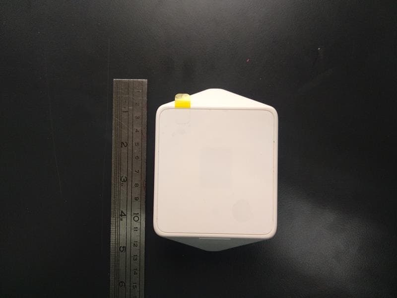
WP3MP843
Jun 30, 2020PIR detector ZigBee
Equipment Class
DTS - Digital Transmission System
WP3MCT350SMA5
Dec 14, 2015Zigbee Door / Window Contact
Equipment Class
DTS - Digital Transmission System