WP3FLD550PG2Flood detector
Visonic Ltd.
Click to zoom
Application Details
- Equipment Class
- DSS - Part 15 Spread Spectrum Transmitter
- Date of Grant
- May 29, 2012
- Application Purpose
- Original Equipment
- Date of Application
- May 28, 2012
- Equipment Note
- Flood detector
- Frequency Range
- 912.75000000 - 919.10600000
- Company
- Visonic Ltd.
- Country
- Israel
Documents & Files
Document Text
Text extracted from the exhibit documents filed with the FCC. Open a document above to read the original.
Users Manual
D-303731 FLD-550 PG2 Installation Instructions 1 FLD-550 PG2 PowerG Wireless Flood Detector Installation Instructions 1. INTRODUCTION The FLD-550 PG2 is a fully supervised two-way indoor, PowerG flood detector, used to detect the presence of water based fluids at any desired location. The FLD-550 PG2 sends the parameters of the specific alarm to the control panel using PowerG two-way communications protocol. The FLD-550 PG2 tamper switch is activated when the cover is removed. A periodic supervision message is transmitted automatically. The control panel is thus informed, at regular intervals, of the unit’s active participation in the system. An LED lights whenever alarm or tamper events are reported. The LED does not light while a supervision message is being transmitted. Operating power is obtained from an on-board 3 V Lithium battery. When the battery voltage is low, a “low battery” message is sent to the receiver. A. Clamp (1 of 3) – attach slightly above flood detector B. Flood sensor C. Water D. Flood sensor cable E. FLD-550 PG2 F. PowerG code alarm G. Alarm system Figure 1. Using the FLD-550 PG2 2. INSTALLATION 2.1 Mounting 1. Attach the flood sensor near the floor. 2. Secure the flood sensor and its cable to the wall using the three wire clamps. One clamp should be fastened immediately above the flood sensor. The flood sensor should be installed only in a vertical position, and facing downward. The remaining two clamps can be used as required (see Figures 1 and 2). Note: To provide better protection against rats, it is recommended that the flood sensor cable be placed inside a metal/plastic pipe. 3. Attach the flood detector to the wall. The flood detector should be placed as high up as possible on the wall to improve communication and to prevent the flood detector itself from coming into contact with water in the event of flooding. 4. Insert a flat-edged screwdriver into the slot and push upward to remove cover. 5. Remove the screw and separate the cover from the base. 6. Remove the PCB board. 7. Mark and drill 2 holes in the mounting surface and fasten the base with 2 countersunk screws. Risk of explosion if battery is replaced by an incorrect type. Dispose of used battery according to manufacturer's instructions. Note: 868 MHz device is illustrated in the above example. The same mounting procedure should be performed for 433 MHz and 915 MHz devices. A. Transmission LED B. 2 -3 m (recommended length) C. Flood Sensor Cable D. Water E. Enroll button F. Tamper switch Note: Flood sensor height according to required flood detection. Recommended 0-3 cm from floor. Figure 2. Correct Mounting of the Flood Detector 2 D-303731 FLD-550 PG2 Installation Instructions 2.2. Enrollment Refer to the PowerMaster panel's Installer's Guide and follow the procedure under the "02:ZONES/DEVICES" option of the Installer Menu. A general description of the procedure is provided in the following flow chart. Step 1 Step 2 Step 3 Step 4 Enter the Installer menu and select “02:ZONES/DEVICES” Select "ADD NEW DEVICE" See Note 1 Enroll the device or enter the device ID Select the desired detector number for the new flood detector Step 5 Step 6 Step 7 Configure Location parameter Enter PARTITIONS. See Note 2 Assign partitions to the detector by pressing the , and buttons on the panel means scroll and select Notes: 1. If the detector is already enrolled, you can configure the detector location parameter and assign partitions via the “Modify Devices” option – see Step 2. 2. PARTITIONS will appear only if PARTITIONING was previously enabled in a panel that supports the Partitioning feature (for further details, see "Partitioning" in the PowerMaster Installer Guide). 3. LOCAL DIAGNOSTICS TEST Before testing, separate the base from the cover (see Figure 2). A. Verify that the FLD-550 transmits (the LED lights briefly) and that a tamper message was received by the panel. B. When you are satisfied that tamper alerts are transmitted properly, put the cover on to return the tamper switch to its normal (undisturbed) position and then secure the front cover to the base with the screw. C. Bring the flood sensor into contact with water. Wait a few seconds and verify that the transmitter LED lights, indicating that transmission is in progress. It is recommended to perform this test every month. D. After 2 seconds the LED blinks 3 times. The following table indicates received signal strength indication. LED response Reception Green LED blinks Strong Orange LED blinks Good Red LED blinks Poor No blinks No communication IMPORTANT! Reliable reception must be assured. Therefore, "poor" signal strength is not acceptable. If you receive a "poor" signal from the device, re-locate it and re-test until a "good" or "strong" signal strength is received. E. Dry the flood sensor using either blotting paper or a rag, thus restoring it to the undisturbed state, and then observe the LED. Note: For detailed Diagnostics Test instructions refer to the control panel Installer's Guide. 4. MISCELLANEOUS COMMENTS Visonic Ltd. wireless systems are very reliable and are tested to high standards. However, due to low transmitting power and limited range (required by FCC and other regulatory authorities), there are some limitations to be considered: A. Receivers may be blocked by radio signals occurring on or near their operating frequencies, regardless of the digital code used. B. A receiver responds only to one transmitted signal at a time. C. Wireless devices should be tested regularly to determine whether there are sources of interference and to protect against faults. The user is cautioned that changes or modifications to the unit, not expressly approved by Visonic Ltd., could void the user’s FCC or other authority to operate the equipment. The digital circuitry of this device has been tested and found to comply with the limits for a Class B digital device, pursuant to Part 15 of the FCC Rules. These limits are designed to provide…
Text truncated - open the document above for the full version.
Cover Letter(s)
Declaration of Authorization We Name: Visonic Ltd. Address: Habarzel street 24, City: Tel Aviv 69710, Country: Israel . Declare that: Agent Company name: Hermon Laboratories Ltd. Address: Harakevet Industrial Zone City: Binyamina 30500 Country Israel is authorized to apply for Certification of the following product(s): Product description: Flood detector Type designation: FLD-550 PG2. Trademark: Visonic . on our behalf. Date: 05/24/2012 Name: Arik Elshtein .. (2) Function: International Standards Department Manager Signature:
Cover Letter(s)
FCC, Request for non-disclosure Date: 16-Jul-10 RF_501, Issue 6 Page 1 of 1 Company Name: Visonic Ltd. Address : Habarzel street 24 City: Tel Aviv 69710 Country: Israel To: Telefication B.V., Dept. FCC TCB Edisonstraat 12A 6902 PK ZEVENAAR The Netherlands Subject: Request for confidentiality FCC ID: WP3FLD550PG2 Reference number: ###### Dear FCC TCB, 1. Long-Term Confidentiality Pursuant to 47 CFR Section 0.459(a) & (b), we hereby requests non-disclosure and confidential treatment of the following materials submitted in support of FCC certification application: Bill(s) of Material Block Diagrams Operational Description Schematic Diagrams Tune-up Procedure Above materials contain secrets, proprietary and technical information, which would customarily be guarded from competitors under 47 CFR, section 0.457(d)(2). Disclosure or publication or any portion of this company confidential material to other parties could cause substantial competitive harm and provide unjustified benefits for competitors. 2. Short-Term Confidentiality (STC) Pursuant to Public Notice DA 04-1705 of the Commission’s policy, in order to comply with the marketing regulations in 47 CFR §2.803 and the importation rules in 47 CFR §2.1204, a pplicant hereby requests Short-Term Confidential treatment of the following materials (note 1): Internal Photos User’s Manual Test Set-up Photos External Photos Justification: Planned Release Date STC: (notes 2, 3, 4, 5) Date: May 23, 2012 Name and signature of applicant: Mr. Arik Elshtein Notes: 1) A document or type of document can only have ONE type of confidentiality! 2) Short-Term confidentiality is in principle for 45 days from date of grant; it can be extended max 3 times (total time 180 days max.)! 3) FCC must be informed when marketing begins earlier. 4) Release takes place automatically thus extension must be requested in time. Telefication does not remind you of this! 5) Request for extension or for release must be received by Telefication at least 7 days before date of actual marketing or before expiration of the STC period
External Photos
Visonic Ltd. FCC ID:WP3FLD550PG2 IC:1467C-FLD550PG2 Page 1 of 3 EXTERNAL PHOTOGRAPHS This document contains 2 photographs Visonic Ltd. FCC ID:WP3FLD550PG2 IC:1467C-FLD550PG2 Page 2 of 3 Photograph No.1 Flood detector FLD-550 PG2 general view Visonic Ltd. FCC ID:WP3FLD550PG2 IC:1467C-FLD550PG2 Page 3 of 3 Photograph No.2 Flood detector FLD-550 PG2 rear side view
ID Label/Location Info
Visonic Ltd. FCC ID:WP3FLD550PG2 IC:1467C-FLD550PG2 Page 1 of 1 Label Label location Label with FCC ID:WP3FLD550PG2 and IC:1467C-FLD550PG2 is located at the rear side panel. The statement according to FCC part 15 §15.19(a)(3) is placed in User’s Guide, page 3 (Application exhibit User_manual_23018). FCC ID:WP3FLD550PG2 IC:1467C-FLD550PG2
Internal Photos
Visonic Ltd. FCC ID:WP3FLD550PG2 IC:1467C-FLD550PG2 Page 1 of 4 INTERNAL PHOTOGRAPHS This document contains 3 photographs Visonic Ltd. FCC ID:WP3FLD550PG2 IC:1467C-FLD550PG2 Page 2 of 4 Photograph No.1 Flood detector FLD-550 PG2 internal view Visonic Ltd. FCC ID:WP3FLD550PG2 IC:1467C-FLD550PG2 Page 3 of 4 Photograph No.2 Flood detector PCB rear side view Visonic Ltd. FCC ID:WP3FLD550PG2 IC:1467C-FLD550PG2 Page 4 of 4 Photograph No.3 Flood detector FLD-550PG2 antenna
RF Exposure Info
Visonic Ltd. FCC ID:WP3FLD550PG2 IC:1467C-FLD550PG2 Exposure limit according to §15.247(i) and RSS-102 The device is classified as mobile. Limit for power density for general population/uncontrolled exposure is f/1500 mW/cm 2 for 300 – 1500 MHz frequency range: P = 912.75/1500 = 0.61 mW/cm 2 The power density P (mW/cm 2 ) = P T / 4 r 2 P T is the transmitted power, which is equal to the peak transmitter output power 21 dBm plus maximum antenna gain -7 dBi, the maximum equivalent isotropically radiated power EIRP is P T = 21 dBm -7 dBi = 14 dBm = 25.1 mW. The power density at 20 cm (minimum safe distance, required for mobile devices), calculated as follows: 25.1 mW / 4 (20 cm) 2 = 0.005 mW/cm 2 << 0.61 mW/cm 2 General public cannot be exposed to dangerous RF level.
Test Report
Hermon Laboratories Ltd. Harakevet Industrial Zone, Binyamina 30500, Israel Tel. +972-4-6288001 Fax. +972-4-6288277 E-mail: [email protected] Page 1 of 79 Report ID: VISRAD_FCC.23018.doc Date of Issue: 4-Apr-12 ELECTRICAL TESTING 0839.01 TEST REPORT ACCORDING TO: FCC 47CFR part 15 subpart C § 15.247 (FHSS) and subpart B, RSS-210 issue 8 Annex 8, ICES-003 Issue 4:2004 FOR: Visonic Ltd. Flood Detector Model: FLD-550 PG2 (915) FCC ID:WP3FLD550PG2 This report is in conformity with ISO/ IEC 17025. The "A2LA Accredited" symbol endorsement applies only to the tests and calibrations that are listed in the scope of Hermon Laboratories accreditation. The test results relate only to the items tested. This test report shall not be reproduced in any form except in full with the written approval of Hermon Laboratories Ltd. Report ID: VISRAD_FCC.23018.doc Date of Issue: 4-Apr-12 Page 2 of 79 Table of contents 1 Applicant information ..................................................................................................................................................... 3 2 Equipment under test attributes .................................................................................................................................... 3 3 Manufacturer information .............................................................................................................................................. 3 4 Test details .................................................................................................................................................................... 3 5 Tests summary .............................................................................................................................................................. 4 6 EUT description ............................................................................................................................................................. 5 6.1 General information ....................................................................................................................................................... 5 6.2 Test configuration .......................................................................................................................................................... 5 6.3 Changes made in the EUT ............................................................................................................................................ 5 6.4 Transmitter characteristics ............................................................................................................................................ 6 7 Transmitter tests according to 47CFR part 15 subpart C and RSS-210 Annex 8 requirements .................................... 7 7.1 20 dB bandwidth ........................................................................................................................................................... 7 7.2 Carrier frequency separation ....................................................................................................................................... 11 7.3 Number of hopping frequencies .................................................................................................................................. 13 7.4 Average time of occupancy ......................................................................................................................................... 16 7.5 Peak output power ...................................................................................................................................................... 19 7.6 Band edge radiated emissions .................................................................................................................................... 25 7.7 Field strength of spurious emissions ........................................................................................................................... 29 7.8 Antenna requirements ................................................................................................................................................. 61 8 Unintentional emissions .............................................................................................................................................. 62 8.1 Radiated emission measurements .............................................................................................................................. 62 9 APPENDIX A Test equipment and ancillaries used for tests ....................................................................................... 68 10 APPENDIX B Measurement uncertainties ................................................................................................................... 69 11 APPENDIX C Test laboratory description ................................................................................................................... 70 12 APPENDIX D Specification references ....................................................................................................................... 70 13 APPENDIX E Test equipment correction factors ......................................................................................................... 71 14 APPENDIX F Abbreviations and acronyms ................................................................................................................. 79 Report ID: VISRAD_FCC.23018.doc Date of Issue: 4-Apr-12 Page 3 of 79 1 Applicant information Client name: Visonic Ltd. Address: Habarzel street 24, Tel Aviv 69710, Israel Telephone: +972 3645 6714 Fax: +972 3645 6788 E-mail: [email protected] Contact name: Mr. Arick Elshtein 2 Equipment under test attributes Product name: Flood Detector Product type: Transceiver Model(s): FLD-550 PG2 (915) Hardware version: 90-204900 Software release: JS 702155 Receipt date 6/21/2011 3 Manufacturer information Manufacturer name: Visonic Ltd. Address:…
Text truncated - open the document above for the full version.
Test Setup Photos
Visonic Ltd. FCC ID:WP3FLD550PG2 IC:1467C-FLD550PG2 Page 1 of 6 SETUP PHOTOGRAPHS This document contains 5 photographs Visonic Ltd. FCC ID:WP3FLD550PG2 IC:1467C-FLD550PG2 Page 2 of 6 Photograph No.1 Setup for spurious emission field strength measurements in the anechoic chamber below 30 MHz Visonic Ltd. FCC ID:WP3FLD550PG2 IC:1467C-FLD550PG2 Page 3 of 6 Photograph No.2 Setup for carrier field strength, OBW, spurious emission field strength measurements in the anechoic chamber in 30 – 1000 MHz range Visonic Ltd. FCC ID:WP3FLD550PG2 IC:1467C-FLD550PG2 Page 4 of 6 Photograph No.3 Setup for spurious emission field strength measurements in the anechoic chamber above 1000 MHz range Visonic Ltd. FCC ID:WP3FLD550PG2 IC:1467C-FLD550PG2 Page 5 of 6 Photograph No.4 Setup for spurious emission field strength measurements at the OATS above 1000 MHz range Visonic Ltd. FCC ID:WP3FLD550PG2 IC:1467C-FLD550PG2 Page 6 of 6 Photograph No.5 Setup for band edge emissions and hopping parameters measurements
Contact Information
Applicant
Zuri Rubin(Certification Manager)
Technical Contact
Hermon Laboratories LtdMichael Nikishin
[email protected]+97246268440
Harakevet Industrial zone · Binyamina · Israel
Test Firm
Hermon Laboratories Ltd.Alexander Usoskin
Technical Specifications
| # | Rule Parts | Frequency Range | Power Output |
|---|---|---|---|
| 1 | 15C | 912.75 MHz - 919.106 MHz | 126.00 mW |
Other Applications from Visonic Ltd.
WP3NEXTCAMPGP
Dec 21, 2023Wireless Motion detector with integrated camera
Equipment Class
DSS - Part 15 Spread Spectrum Transmitter
WP3RP600PGP
May 16, 2023Wireless Repeater for PowerG Communications
Equipment Class
DSS - Part 15 Spread Spectrum Transmitter
WP3PGMODIQREM
Jun 02, 2021Power-G Modem iQ Remote
Equipment Class
DSS - Part 15 Spread Spectrum Transmitter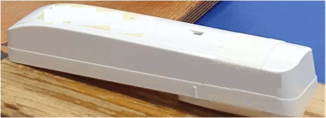
WP3SD304EPG2
Jan 03, 2021PowerG Wireless Shock Detector
Equipment Class
DSS - Part 15 Spread Spectrum Transmitter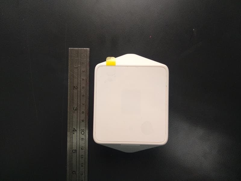
WP3MP843
Jun 30, 2020PIR detector ZigBee
Equipment Class
DTS - Digital Transmission System