WP3GSD442NCO gas detector
Visonic Ltd.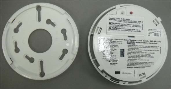
Click to zoom
Application Details
- Equipment Class
- DSS - Part 15 Spread Spectrum Transmitter
- Date of Grant
- Sep 29, 2014
- Application Purpose
- Original Equipment
- Date of Application
- Sep 28, 2014
- Equipment Note
- CO gas detector
- Frequency Range
- 912.75000000 - 919.10600000
- Company
- Visonic Ltd.
- Country
- Israel
Documents & Files
Document Text
Text extracted from the exhibit documents filed with the FCC. Open a document above to read the original.
Users Manual
D-303404 GSD-442 PG2 Installation Instructions 1 GSD-442 PG2 PowerG Wireless Carbon Monoxide (CO) Detector Installation Instructions 1. INTRODUCTION The Wireless PowerG Two-way Carbon Monoxide (CO) Detector is designed to monitor the CO gas level in residential dwellings and give early warning before potentially dangerous levels exist. The CO alarm is transmitted to the PowerMaster control panel and presented on its display. The CO gas is considered to be a highly dangerous poisonous gas because it is colorless, odorless, tasteless and very toxic. Presence of CO gas inhibits the blood's capacity to transport oxygen throughout the body, which can eventually lead to brain damage. CO gas is produced by incomplete combustion of fuels (such as natural gas, propane, heating oil, kerosene, coal, charcoal, gasoline or wood) that can occur in any device that depends on burning for energy and heat (such as furnaces, boilers, room heaters, hot water heaters, stoves, grills and in any gasoline powered vehicle or engine). Before CO harmful level is reached, the detector's internal buzzer beeps sound periodically and the detector's red LED flashes. In this condition, the buzzer sound can be stopped for 6 minutes by pressing the TEST/MUTE switch. It will not correct the CO gas problem, but will temporarily silence the buzzer while you correct the problem. After 6 minutes, the detector restarts alarm if the CO level remains high. The detector provides low battery and detector end-of-life indications. Caution: The detector expiry date is stamped on the detector. After the expiry date, the detector should not be used - do not wait for end-of-life indication!! The detector is continuously self-tested and has a TEST button that enables the user to test the detector anytime. Note: The TEST/MUTE switch functions as TEST switch (in normal operation) or as MUTE switch (in alarm condition). The tamper switch actuator (Figure 3), is pressed against the bracket when the unit is attached to the bracket. Removal of the unit from the bracket causes the switch contacts to open, creating a tamper event, which is reported by the transmitter to the alarm system control panel. A B C A. Alarm (red) LED B. Battery (green) / Fault (yellow) LED C. TEST / MUTE button Figure 1 - General View 2. PREPARATIONS 2.1 Disassembly 1 2 A B 1. Hold the bracket with one hand 2. Rotate the detector as shown and pull it from the bracket A. Bracket B. Detector Figure 2. Separating the Detector from Its Bracket 2.2 Enrollment Refer to the PowerMaster Installer Guide and follow the procedure under the "02:ZONES/DEVICES" option of the Installer Menu. A general description of the procedure is provided in the following flow chart. Step 1 Step 2 Step 3 Step 4 Step 5 Enter the Installer menu and select “02:ZONES/DEVICES” Select "ADD NEW DEVICE" Option Enroll the device or Enter the device ID See Note Select the desired Zone Number Configure the Location Parameter means scroll and select Note: i) Insert the battery (see Figure 3) to enroll the gas detector. -or- ii) Key in the device ID of the gas detector and at a later stage, when the installation makes possible, insert the battery. Z07.LOCATION ID No. 220‐XXXX Z07:GAS Sensor ENTR ID:XXX‐XXXX ENROLL NOW or ADD NEW DEVICES 02.ZONES/DEVICES 2 D-303404 GSD-442 PG2 Installation Instructions 2.3 Inserting Battery 9 volts 1 A C B D Insert battery (see figure 3). 1. Open the battery cover and connect the battery to its terminals without the insulator. Verify proper polarity. A. Red button B. Battery connector C. Tab (1 of 4) D. Tamper switch actuator Caution! Risk of explosion if battery is replaced by an incorrect type. Dispose of used batteries according to the manufacturer's instructions. Figure 3. Detector Rear Side 3. INSTALLATION 3.1 Mounting The detector can be mounted on a wall or ceiling. For EN approved sites, only ceiling installation is allowed. It must be mounted with its bracket (when it is attached to its bracket the tamper switch is pressed and the detector automatic reset is performed). ! Warnings Installation must be performed by a qualified individual. Failure to properly install, test and maintain a CO detector may cause it to fail, resulting in loss of life! Installation of the CO detector should not be used as a substitute for proper installation, use and maintenance of fuel burning appliances, including appropriate ventilation and exhaust systems. Unauthorized removal of the unit from the bracket will initiate a tamper alert! ! Warning - The battery must be inserted into the detector otherwise you will not be able to close the detector. 3.2 Diagnostic Test For Diagnostics Test instructions refer to the control panel Installer Guide. ! WARNING: The test switch is the only proper way to test the CO detector. Never use vehicle exhaust! Exhaust may cause permanent damage and void your warranty. B. Communication Test Create a tamper alarm at the installation location and verify that tamper message is received by the control panel / receiver. 1 2 3 UP A 1. Locate the bracket on the mounting surface so that the word "UP" appears in the direction shown in Figure 4 (this ensures that the text on the detector's stickers will be easily readable). 2. Mark and drill 2 holes in the mounting surface. Fasten the bracket to the mounting surface with 2 screws. 3. Align the detector's tabs (see Figure 3) with the bracket slots and rotate the detector as shown. Pull the detector outward to verify that it is securely attached. A. Mounting Surface Figure 4. Mounting 4. MAINTENANCE ! Warning: Press the detector's TEST button once every week to ensure proper operation of the detector. When low battery alarm exists (see specifications) immediately replace the battery (see figure 3). Once a month, use a vacuum cleaner to clean the air vents occasionally, to keep them free of dust. D-303404 GSD-442 PG2 Installation Instructions 3 APPENDICES Appendix A - Specifications CO DETECTION Detection Pr…
Text truncated - open the document above for the full version.
Cover Letter(s)
September 16, 2014 Telefication B.V. Attn: Dept. FCC TCB Edisonstraat 12A 6902 PK ZEVENAAR The Netherlands Subject: Application for certification of a wireless carbon monoxide (CO) gas detector, FCC ID:WP3GSD442N Dear Gentlemen, Please find attached our application for certification of a wireless carbon monoxide (CO) gas detector, FCC ID:WP3GSD442N, prepared in accordance with FCC Rules, parts 2 and 15, section 15.247. The product testing and this application for certification were performed by Hermon Laboratories, which is listed by FCC, Registration Numbers 90623, 90624. The FCC Designation Number is US1003. Hermon Labs responsible person is Mr. Michael Nikishin, tel: +972 4626 8440, fax:+972 4628 8277, e-mail: [email protected]. We hope this application satisfies your requirements. Please send an invoice to Hermon Labs. Arick Elshtein, International Standards Department Manager Visonic Ltd.
Cover Letter(s)
RF_160, Issue 03 Declaration of Authorization We Name: Visonic Ltd. Address: 24 Habarzel street City: Tel Aviv 61920. Country: Israel. Declare that: Name Representative of agent: ............. (1) Agent Company name: Hermon Laboratories Ltd. . Address: Harakevet Industrial Zone .. City: Binyamina 30500 .. Country Israel . is authorized to apply for Certification of the following product(s): Product description: CO gas detector . Type designation: GSD-442 PG2 Trademark: Visonic . on our behalf. Date: July 31, 2014 .. City: Tel Aviv.. Name: Arick Elshtein .. (2) Function: International Standards Department Manager ............................... Signature: . Notes: (1): Required for FCC application (2): For FCC it must be the Grantee Code “owner” or the authorized agent.
External Photos
Visonic Ltd. FCC ID:WP3GSD442N IC:1467C-GSD442N Page 1 of 3 EXTERNAL PHOTOGRAPHS This document contains 2 photographs Visonic Ltd. FCC ID:WP3GSD442N IC:1467C-GSD442N Page 2 of 3 Photograph No.1 CO gas detector front view Visonic Ltd. FCC ID:WP3GSD442N IC:1467C-GSD442N Page 3 of 3 Photograph No.2 CO gas detector rear side view
ID Label/Location Info
Visonic Ltd. FCC ID:WP3GSD442N IC:1467C-GSD442N Page 1 of 2 Label location Label with FCC ID:WP3GSD442N and IC:1467C-GSD442N is located at the rear side panel. Visonic Ltd. FCC ID:WP3GSD442N IC:1467C-GSD442N Page 2 of 2 Label
Internal Photos
Visonic Ltd. FCC ID:WP3GSD442N IC:1467C-GSD442N Page 1 of 7 INTERNAL PHOTOGRAPHS This document contains 6 photographs Visonic Ltd. FCC ID:WP3GSD442N IC:1467C-GSD442N Page 2 of 7 Photograph No.1 CO gas detector internal view Visonic Ltd. FCC ID:WP3GSD442N IC:1467C-GSD442N Page 3 of 7 Photograph No.2 Main PCB with RFD module front view Visonic Ltd. FCC ID:WP3GSD442N IC:1467C-GSD442N Page 4 of 7 Photograph No.3 Main PCB with RFD module removed Visonic Ltd. FCC ID:WP3GSD442N IC:1467C-GSD442N Page 5 of 7 Photograph No.4 Main PCB second side view Visonic Ltd. FCC ID:WP3GSD442N IC:1467C-GSD442N Page 6 of 7 Photograph No.5 RFD module front view Visonic Ltd. FCC ID:WP3GSD442N IC:1467C-GSD442N Page 7 of 7 Photograph No.6 RFD module second side view
RF Exposure Info
Visonic Ltd. FCC ID:WP3GSD442N IC:1467C-GSD442N Exposure limit according to §15.247(i) and RSS-102 The device is classified as mobile. Limit for power density for general population/uncontrolled exposure is f/1500 mW/cm 2 for 300 – 1500 MHz frequency range: P = 912.75/1500 = 0.61 mW/cm 2 The power density P (mW/cm 2 ) = P T / 4 r 2 P T is the transmitted power, which is equal to the peak transmitter output power 19.8 dBm plus maximum antenna gain -3 dBi, the maximum equivalent isotropically radiated power EIRP is P T = 19.8 dBm -3 dBi = 16.8 dBm = 47.9 mW. The power density at 20 cm (minimum safe distance, required for mobile devices), calculated as follows: 47.9 mW / 4 (20 cm) 2 = 0.0095 mW/cm 2 << 0.61 mW/cm 2 General public cannot be exposed to dangerous RF level.
Test Report
Hermon Laboratories Ltd. Harakevet Industrial Zone, Binyamina 30500, Israel Tel. +972-4-6288001 Fax. +972-4-6288277 E-mail: [email protected] Page 1 of 82 Report ID: VISRAD_FCC_IC.24998.docx Date of Issue: 23-Jun-14 ELECTRICAL TESTING 0839.01 TEST REPORT ACCORDING TO: FCC 47CFR part 15 subpart C § 15.247 (FHSS), RSS-210 issue 8 Annex 8 FOR: Visonic Ltd. CO gas detector (915 MHz) Model:GSD-442 PG2 FCC ID:WP3GSD442N IC:1467C-GSD442N This report is in conformity with ISO/ IEC 17025. The "A2LA Accredited" symbol endorsement applies only to the tests and calibrations that are listed in the scope of Hermon Laboratories accreditation. The test results relate only to the items tested. This test report shall not be reproduced in any form except in full with the written approval of Hermon Laboratories Ltd. Report ID: VISRAD_FCC_IC.24998.docx Date of Issue: 23-Jun-14 Page 2 of 82 Table of contents 1 Applicant information ..................................................................................................................................................... 3 2 Equipment under test attributes .................................................................................................................................... 3 3 Manufacturer information .............................................................................................................................................. 3 4 Test details .................................................................................................................................................................... 3 5 Tests summary .............................................................................................................................................................. 4 6 EUT description ............................................................................................................................................................. 5 6.1 General information ....................................................................................................................................................... 5 6.2 Test configuration .......................................................................................................................................................... 5 6.3 Changes made in EUT .................................................................................................................................................. 5 6.4 EUT positions during testing ......................................................................................................................................... 6 6.5 Transmitter characteristics ............................................................................................................................................ 7 7 Transmitter tests according to 47CFR part 15 subpart C and RSS-210 Annex 8 requirements .................................... 8 7.1 20 dB bandwidth ........................................................................................................................................................... 8 7.2 Carrier frequency separation ....................................................................................................................................... 12 7.3 Number of hopping frequencies .................................................................................................................................. 15 7.4 Average time of occupancy ......................................................................................................................................... 19 7.5 Peak output power ...................................................................................................................................................... 23 7.6 Band edge radiated emissions .................................................................................................................................... 32 7.7 Field strength of spurious emissions ........................................................................................................................... 37 7.8 Antenna requirements ................................................................................................................................................. 68 8 APPENDIX A Test equipment and ancillaries used for tests ....................................................................................... 69 9 APPENDIX B Measurement uncertainties ................................................................................................................... 70 10 APPENDIX C Test laboratory description ................................................................................................................... 71 11 APPENDIX D Specification references ....................................................................................................................... 71 12 APPENDIX E Test equipment correction factors ......................................................................................................... 72 13 APPENDIX F Abbreviations and acronyms ................................................................................................................. 82 Report ID: VISRAD_FCC_IC.24998.docx Date of Issue: 23-Jun-14 Page 3 of 82 1 Applicant information Client name: Visonic Ltd. Address: 24 Habarzel street, Tel Aviv 69710, Israel Telephone: +972 3 645 6714 Fax: +972 3645 6788 E-mail: [email protected] Contact name: Mr. Arik Elshtein 2 Equipment under test attributes Product name: Wireless PowerG Two-way Carbon Monoxide (CO) Detec Product type: Transceiver Model(s): GSD-442 PG2 (CO) Hardware version: V2.6 Software release: 1106 Receipt date 17-Oct-13 3 Manufacturer information Manufacturer name: Visonic Ltd. Address: 24 Habarzel street, Tel Aviv 69710, Israel Telephone: +972 3 645 6714 Fax: +972 3645 6788 E-Mail: [email protected] Contact name: Mr. Ar…
Text truncated - open the document above for the full version.
Test Setup Photos
Visonic Ltd. FCC ID:WP3GSD442N IC:1467C-GSD442N Page 1 of 8 SETUP PHOTOGRAPHS This document contains 7 photographs Visonic Ltd. FCC ID:WP3GSD442N IC:1467C-GSD442N Page 2 of 8 Photograph No.1 Setup for spurious emission field strength measurements in the anechoic chamber below 30 MHz Visonic Ltd. FCC ID:WP3GSD442N IC:1467C-GSD442N Page 3 of 8 Photograph No.2 Setup for spurious emission field strength measurements in the anechoic chamber in 30 – 1000 MHz range Visonic Ltd. FCC ID:WP3GSD442N IC:1467C-GSD442N Page 4 of 8 Photograph No.3 Setup for carrier field strength measurements at the OATS in 30 – 1000 MHz range, EUT in X-axis position Visonic Ltd. FCC ID:WP3GSD442N IC:1467C-GSD442N Page 5 of 8 Photograph No.4 Setup for carrier field strength measurements at the OATS in 30 – 1000 MHz range, EUT in Y-axis position Visonic Ltd. FCC ID:WP3GSD442N IC:1467C-GSD442N Page 6 of 8 Photograph No.5 Setup for spurious emission field strength measurements in the anechoic chamber above 1000 MHz range Visonic Ltd. FCC ID:WP3GSD442N IC:1467C-GSD442N Page 7 of 8 Photograph No.6 Setup for band edge emissions and hopping parameters measurements Visonic Ltd. FCC ID:WP3GSD442N IC:1467C-GSD442N Page 8 of 8 Photograph No.7 Setup for OBW measurements
Contact Information
Applicant
Zuri Rubin(Certification Manager)
Technical Contact
Hermon Laboratories Ltd.Michael Nikishin
[email protected]97246268840
Harakevet Industrial zone, P.O.Box 23 · Israel
Non-Technical Contact
Visonic Ltd.Arick Elshtein
[email protected]97236456714
Test Firm
Hermon Laboratories Ltd.Alexander Usoskin
Technical Specifications
| # | Rule Parts | Frequency Range | Power Output |
|---|---|---|---|
| 1 | 15C | 912.75 MHz - 919.106 MHz | 95.00 mW |
Other Applications from Visonic Ltd.
WP3NEXTCAMPGP
Dec 21, 2023Wireless Motion detector with integrated camera
Equipment Class
DSS - Part 15 Spread Spectrum Transmitter
WP3RP600PGP
May 16, 2023Wireless Repeater for PowerG Communications
Equipment Class
DSS - Part 15 Spread Spectrum Transmitter
WP3PGMODIQREM
Jun 02, 2021Power-G Modem iQ Remote
Equipment Class
DSS - Part 15 Spread Spectrum Transmitter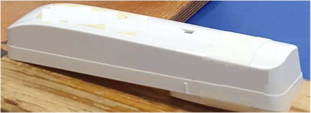
WP3SD304EPG2
Jan 03, 2021PowerG Wireless Shock Detector
Equipment Class
DSS - Part 15 Spread Spectrum Transmitter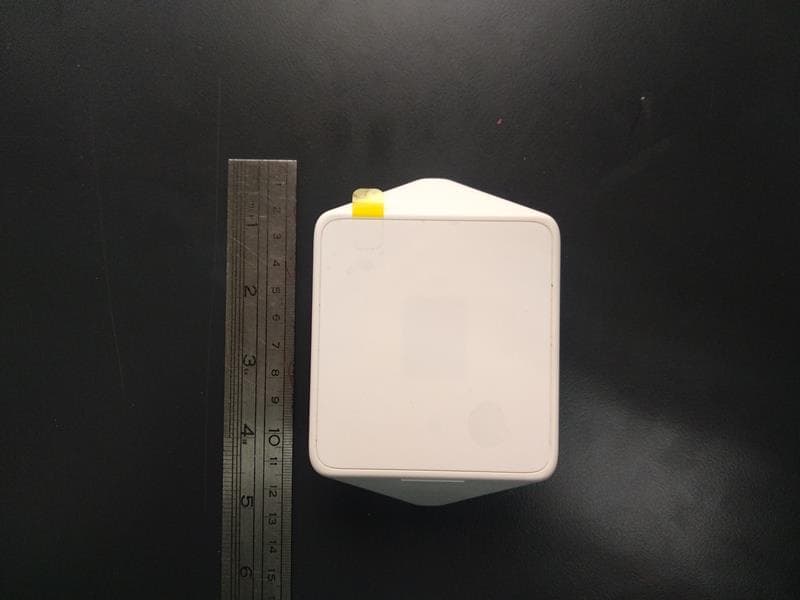
WP3MP843
Jun 30, 2020PIR detector ZigBee
Equipment Class
DTS - Digital Transmission System