WP3KP141PG2Remote keypad
Visonic Ltd.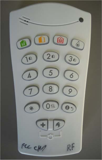
Click to zoom
Application Details
- Equipment Class
- DCD - Part 15 Low Power Transmitter Below 1705 kHz
- Date of Grant
- Sep 04, 2011
- Application Purpose
- Original Equipment
- Date of Application
- Aug 08, 2011
- Equipment Note
- Remote keypad
- Frequency Range
- 0.12000000 - 0.12000000
- Company
- Visonic Ltd.
- Country
- Israel
Documents & Files
Document Text
Text extracted from the exhibit documents filed with the FCC. Open a document above to read the original.
Users Manual
D-303015 1 KP-140 PG2/KP-141 PG2 Portable Remote Wireless 2-Way Keypad User’s Guide 1. INTRODUCTION KP-140 PG2 and KP-141 PG2 are 2-way PowerG wireless keypads for the PowerMaster family control panels. The KP-141 PG2 is the same as the KP-140 PG2 but also includes a built-in proximity RFID tag reader. Both keypads enable most common everyday user functions: Arm and Disarm the alarm system. Initiate Emergency, Fire and Panic alarms. Control X-10 devices and PGM output. Perform one of the AUX (auxiliary) predefined functions. Review system Status. When authorization is required, for example, to arm or disarm the system, the user can enter his PIN Code via the built-in numerical keypad or alternatively present a valid proximity tag to the built-in tag reader (only with KP-141PG2) located at "N" in Figure 1. In addition, the KP-140 PG2/KP-141 PG2 keypad supports panels featuring Partitions. Partitioning allows you to have up to three controllable areas; each partition can be armed and disarmed independently regardless of the status of the other two partitions by the same or different users (see buttons marked "E" in Figure 1). The keypads can be wall mounted using the supplied bracket or be used as portable units. For compliance with various international standards, the keypads are equipped with two tamper switches that can be configured to detect when the cover of the battery compartment is removed or when the unit is removed from its mounting bracket. Other features of the KP-140 PG2/KP-141 PG2 keypad include: Status, alarm memory, trouble and Ready / Not-Ready indications. Automatic reporting of low battery voltage. Keypad back lighting. Exit/entry beeps Tag reader can also be used to enroll proximity tags into the panel. Long-life 4-5 years battery life expectancy (for typical use), 3 VDC lithium battery. B A C D E F G H I J K L M N A. ARM HOME H. AUX / ENROLLMENT B. ARM AWAY I. EMERGENCY ALARM C. DISARM J. FIRE ALARM D. X-10 / PGM K. PANIC ALARM E. PARTITION SELECTION L. BUZZER INDICATOR F. ARM INSTANT M. LED INDICATOR G. STATUS / ESCAPE N. TAG READER Figure 1 - External View 2. INSTALLATION 2.1 Mounting and Battery Replacement 3 A 1 2 1. Drill 2 holes in mounting surface, insert wall anchors and fasten the bracket with 2 screws. 2. Place the "Visual Indications" sticker within the frame. 3. Slide the keypad into the bracket. A. Magnet (activates back tamper when bracket is removed from the wall). Figure 2 - Mounting 2 1 A 1. Slide out the cover. 2. Replace the battery (verify proper polarity) and close the cover. A. Battery compartment tamper switch Figure 3 - Battery Replacement 2.2. ENROLLMENT Refer to the PowerMaster panel's Installer Guide and follow the procedure under the "02:ZONES/DEVICES" option of the Installer Menu a general description of which is provided in the following flow chart. Step 1 Step 2 Step 3 Step 4 Step 5 Enter the Installer menu and select “ZONES / DEVICES” Select "ADD NEW DEVICE" Option See Note [1] Enroll the device or Enter the device ID Select the desired Zone Number Configure Location, Zo n Paramete Means scroll and select K06.DEV SETTINGS K06.SET CHIME K06.ZK06.LOCATION ID No. 370-XXXX K06: Keypad ENTR ID:XXX-XXXX ENROLL NOW or MODIFY DEVICES ADD NEW DEVICES 02.ZONES/DEVICES D-303015 3 Notes: [1] If the keypad is already enrolled you can configure the keypad parameters via the “Modify Devices” option – see Step 2. [2] Select the "Device Settings" option and refer to section 2.3 to configure the keypad parameters. 2.3. Configuring the Keypad Parameters Enter the menu and follow the configuration instructions for the KP-140 PG2/KP-141 PG2 keypad as described in the following table. Option Configuration Instructions Here you determine which of the two tampers (i.e. battery compartment cover and wall tamper) will be active. Optional settings: Disabled (default); Wall only; Battery only. Here you determine whether or not the control panel will monitor supervision messages sent by the keypad or not (see Note). Optional settings: ON (default) or OFF. Note: Every 5 minutes the keypad performs a communication test session with the control panel (i.e. "Supervision signal) to check the integrity and quality of the Radio link. If the keypad does not report a supervision signal at least once within a predefined time window, a “MISSING” trouble alert is initiated. Therefore, if you intend to take the keypad out of the protected premises you must switch the Supervision OFF to avoid the trouble alert. Here you determine whether the keypad will sound the exit and entry beeps, or not, or whether the keypad will sound the beeps only when the system is armed AWAY and not when it is armed HOME. Optional settings: ON; OFF (default) and OFF @ Home. Here you select the function of the (AUX) button . Four options are offered: Not used: No function assigned to AUX button. Stop Beeps: Pressing the AUX button will cause the control panel and other devices in the system (such as keypads, sirens etc.) to stop beeping (for example during exit or entry delays). Skip exit delay: Pressing the AUX button will immediately stop the exit delay. PGM: Pressing the AUX button will activate the PGM output. The functions of the PGM output is configured at the corresponding sections of the control panel’s Installer Guide (see “OUTPUTS” menu) and User Guide (see “SCHEDULER ” menu). Optional settings: Not Used (default); Stop Beeps; Skip exit delay; and PGM. 2.4 Enrollment of Proximity Tags The built-in proximity tag reader of the KP-141PG2 can be also used to enroll proximity tags into the PowerMaster panel via the keypad as described in the corresponding section of the control panel's User or Installer Guide, or as explained in the general description provided below. Step 1 Step 2 Step 3 Step 4 Enter the Installer menu of the control panel and select the “02:ZONES/DEVICES” Select the "ADD NEW DEVICES" option When "ENROLL NOW" is displayed, press …
Text truncated - open the document above for the full version.
Cover Letter(s)
Declaration of Authorization We Name: Visonic Ltd. Address: Habarzel street 24, City: Tel Aviv 69710, Country: Israel . Declare that: Agent Company name: Hermon Laboratories Ltd. Address: Harakevet Industrial Zone City: Binyamina 30500 Country Israel is authorized to apply for Certification of the following product(s): Product description: 1) Remote keypad . Type designation: 1) KP-140 PG2;2) KP-141 PG2. Trademark: Visonic . on our behalf. Date: 7/05/2011 Name: Arik Elshtein .. (2) Function: International Standards Department Manager Signature:
Cover Letter(s)
FCC, Request for non-disclosure Date: 16-Jul-10 RF_501, Issue 6 Page 1 of 1 Company Name: Visonic Ltd. Address : Habarzel street 24 City: Tel Aviv 69710 Country: Israel To: Telefication B.V ., Dept. FCC TCB Edisonstraat 12A 6902 PK ZEVENAAR The Netherlands Subject: Request for confidentiality FCC ID: WP3KP141PG2 Reference number: ###### Dear FCC TCB, 1. Long-Term Confidentiality Pursuant to 47 CFR Section 0.459(a) & (b), we hereby requests non-disclosure and confidential treatment of the following materials submitted in support of FCC certification application: Bill(s) of Material Block Diagrams Operational Description Schematic Diagrams Tune-up Procedure Above materials contain secrets, proprietary and technical information, which would customarily be guarded from competitors under 47 CFR, section 0.457(d)(2). Disclosure or publication or any portion of this company confidential material to other parties could cause substantial competitive harm and provide unjustified benefits for competitors. 2. Short-Term Confidentiality (STC) Pursuant to Public Notice DA 04-1705 of the Commission’s policy, in order to comply with the marketing regulations in 47 CFR §2.803 and the importation rules in 47 CFR §2.1204, a pplicant hereby requests Short-Term Confidential treatment of the following materials (note 1): Internal Photos User’s Manual Test Set-up Photos External Photos Justification: Planned Release Date STC: (notes 2, 3, 4, 5) Date: July 5, 2011 Name and signature of applicant: Mr. Arik Elshtein Notes: 1) A document or type of document can only have ONE type of confidentiality! 2) Short-Term confidentiality is in principle for 45 days from date of grant; it can be extended max 3 times (total time 180 days max.)! 3) FCC must be informed when marketing begins earlier. 4) Release takes place automatically thus extension must be requested in time. Telefication does not remind you of this! 5) Request for extension or for release must be received by Telefication at least 7 days before date of actual marketing or before expiration of the STC period
External Photos
Visonic Ltd. FCC ID:WP3KP141PG2 IC:1467C-KP141PG2 Page 1 of 5 EXTERNAL PHOTOGRAPHS This document contains 4 photographs Visonic Ltd. FCC ID:WP3KP141PG2 IC:1467C-KP141PG2 Page 2 of 5 Photograph No.1 Remote keypad front view Visonic Ltd. FCC ID:WP3KP141PG2 IC:1467C-KP141PG2 Page 3 of 5 Photograph No.2 Remote keypad rear side view Visonic Ltd. FCC ID:WP3KP141PG2 IC:1467C-KP141PG2 Page 4 of 5 Photograph No.3 Remote keypad rear side with cover removed Visonic Ltd. FCC ID:WP3KP141PG2 IC:1467C-KP141PG2 Page 5 of 5 Photograph No.4 Remote keypad rear side with cover and battery removed
ID Label/Location Info
Visonic Ltd. FCC ID:WP3KP141PG2 IC:1467C-KP141PG2 Page 1 of 2 Label of KP-141 PG remote keypad Visonic Ltd. FCC ID:WP3KP141PG2 IC:1467C-KP141PG2 Page 2 of 2 Label location Label with FCC ID:WP3KP141PG2 and IC:1467C-KP141PG2 will be located at the rear side panel. The statement according to FCC part 15 §15.19(a)(3) is placed in User’s Guide, page 4 (Application exhibit User_manual_21632). FCC ID:WP3KP141PG2 IC:1467C-KP141PG2
Internal Photos
Visonic Ltd. FCC ID:WP3KP141PG2 IC:1467C-KP141PG2 Page 1 of 9 INTERNAL PHOTOGRAPHS This document contains 8 photographs Visonic Ltd. FCC ID:WP3KP141PG2 IC:1467C-KP141PG2 Page 2 of 9 Photograph No.1 Remote keypad internal view Visonic Ltd. FCC ID:WP3KP141PG2 IC:1467C-KP141PG2 Page 3 of 9 Photograph No.2 Remote keypad internal view Visonic Ltd. FCC ID:WP3KP141PG2 IC:1467C-KP141PG2 Page 4 of 9 Photograph No.3 Main board with RFD and RFID modules Visonic Ltd. FCC ID:WP3KP141PG2 IC:1467C-KP141PG2 Page 5 of 9 Photograph No.4 Main PCB second side view Visonic Ltd. FCC ID:WP3KP141PG2 IC:1467C-KP141PG2 Page 6 of 9 Photograph No.5 RFD module and RFID reader close view Visonic Ltd. FCC ID:WP3KP141PG2 IC:1467C-KP141PG2 Page 7 of 9 Photograph No.6 RFD module Visonic Ltd. FCC ID:WP3KP141PG2 IC:1467C-KP141PG2 Page 8 of 9 Photograph No.7 RFD module second side view Visonic Ltd. FCC ID:WP3KP141PG2 IC:1467C-KP141PG2 Page 9 of 9 Photograph No.8 RFD module and RFID reader second side view
RF Exposure Info
Visonic Ltd. FCC ID:WP3KP141PG2 Page 1 of 1 RF exposure information according to FCC CFR 47 part 15, §15.247(i), part 2, §2.1093 The remote keypad is a portable device operating in 912.750 – 919.106 MHz band. It is equipped with an integrates internal antenna. No SAR evaluation required if a transmitter power is below the following low threshold: 60/f (GHz) [mW] = 60/0.915863 [mW] = 65.5 [mW]. Tunable range, GHz Flow Fhigh Center of tunable band, GHz 60/f SAR limitation, mW 0.912750 0.919106 0.915863 65.5 Maximum measured transmitter power: Pout conducted Pout EIRP dBm mW Maximum antenna gain, dBi dBm mW 24.5 282 -8 16.5 44.7 According to the manufacturer’s declaration in every 6 min the device transmits 2 supervision messages of 6 ms duration each and 2 messages following a key press of 10 ms duration each. Total duration is 32 ms. The duty cycle is 9 x10 –5 . Maximum conducted power is 282 mW. Equivalent conducted power is 282 mW x duty cycle = 282 mW x 9 x10 –5 = 254 x10 –4 mW. Threshold for no SAR evaluation is 65.5 mW. Conclusion: No SAR evaluation is required since the maximum transmitter radiated power is below the FCC threshold.
Test Report
Hermon Laboratories Ltd. Harakevet Industrial Zone, Binyamina 30500, Israel Tel. +972-4-6288001 Fax. +972-4-6288277 E-mail: [email protected] Page 1 of 26 Report ID: VISRAD_FCC.21632_15.209.doc Date of Issue: July 2011 ELECTRICAL TESTING 0839.01 TEST REPORT ACCORDING TO: FCC 47CFR part 15 subpart C § 15.209 and RSS-210 issue 8 section 2.5.1 FOR: Visonic Ltd. RFID tag reader of Remote keypad Model: KP-141 PG2 This report is in conformity with ISO/ IEC 17025. The "A2LA Accredited" symbol endorsement applies only to the tests and calibrations that are listed in the scope of Hermon Laboratories accreditation. The test results relate only to the items tested. This test report shall not be reproduced in any form except in full with the written approval of Hermon Laboratories Ltd. Report ID: VISRAD_FCC.21632_15.209.doc Date of Issue: July 2011 Page 2 of 26 Table of contents 1 Applicant information .........................................................................................................................................................3 2 Equipment under test attributes ........................................................................................................................................3 3 Manufacturer information ..................................................................................................................................................3 4 Test details ........................................................................................................................................................................3 5 Tests summary ..................................................................................................................................................................4 6 EUT description .................................................................................................................................................................5 6.1 General information ...........................................................................................................................................................5 6.2 Test configuration ..............................................................................................................................................................5 6.3 Changes made in the EUT ................................................................................................................................................5 6.4 EUT positions during testing .............................................................................................................................................6 7 Transmitter tests according to 47CFR part 15 subpart C and RSS-210 requirements...................................................8 7.1 Field strength of emissions................................................................................................................................................8 7.2 Antenna requirements .....................................................................................................................................................17 7.3 Occupied bandwidth test .................................................................................................................................................18 8 APPENDIX A Test equipment and ancillaries used for tests..........................................................................................20 9 APPENDIX B Measurement uncertainties ......................................................................................................................21 10 APPENDIX C Test laboratory description .......................................................................................................................22 11 APPENDIX D Specification references ...........................................................................................................................22 12 APPENDIX E Test equipment correction factors ............................................................................................................23 13 APPENDIX F Abbreviations and acronyms ....................................................................................................................26 Report ID: VISRAD_FCC.21632_15.209.doc Date of Issue: July 2011 Page 3 of 26 1 Applicant information Client name: Visonic Ltd. Address: Habarzel street 24, Tel Aviv 69710, Israel Telephone: +972 3645 6714 Fax: +972 3645 6788 E-mail: [email protected] Contact name: Mr. Arick Elshtein 2 Equipment under test attributes Product name: RFID tag reader of Remote keypad Product type: Transmitter Model(s): KP-141 PG2 Hardware version: 90-204024 Software release: JS-701195, version 1.0.09 Receipt date 6/28/2011 3 Manufacturer information Manufacturer name: Visonic Ltd. Address: Habarzel street 24, Tel Aviv 69710, Israel Telephone: +972 3645 6714 Fax: +972 3645 6788 E-Mail: [email protected] Contact name: Mr. Arick Elshtein 4 Test details Project ID: 21632 Location: Hermon Laboratories Ltd. Harakevet Industrial Zone, Binyamina 30500, Israel Test started: 6/28/2011 Test completed: 6/28/2011 Test specification(s): FCC 47CFR part 15, subpart C, §15.209; RSS-210 issue 8 section 2.5.1, RSS-Gen issue 3 Table 6 Report ID: VISRAD_FCC.21632_15.209.doc Date of Issue: July 2011 Page 4 of 26 5 Tests summary Test Status Transmitter characteristics FCC section 15.209, RSS-Gen section 7.2.5, Field strength of emissions Pass FCC section 15.203, RSS-Gen section 7.1.2, Antenna requirement Pass RSS-Gen, Section 4.6.1, Occupied bandwidth Tested Testing was completed against all relevant requirements of the test standard. The results obtained indicate that the product under test complies in full with the requirements tested. The test results relate only to the items tested. Pass/ fail decision was based on nominal values. Name and Title Date Signature Tested by: Mr. S. Samokha, test engineer June 28, 201…
Text truncated - open the document above for the full version.
Test Setup Photos
Visonic Ltd. FCC ID:WP3KP141PG2 IC:1467C-KP141PG2 Page 1 of 6 SETUP PHOTOGRAPHS This document contains 5 photographs Visonic Ltd. FCC ID:WP3KP141PG2 IC:1467C-KP141PG2 Page 2 of 6 Photograph No.1 Setup for spurious emission field strength measurements in the anechoic chamber below 30 MHz Visonic Ltd. FCC ID:WP3KP141PG2 IC:1467C-KP141PG2 Page 3 of 6 Photograph No.2 Setup for hopping frequencies and spurious emission field strength measurements in the anechoic chamber in 30 – 1000 MHz range Visonic Ltd. FCC ID:WP3KP141PG2 IC:1467C-KP141PG2 Page 4 of 6 Photograph No.3 Setup for spurious emission field strength measurements in the anechoic chamber above 1000 MHz range Visonic Ltd. FCC ID:WP3KP141PG2 IC:1467C-KP141PG2 Page 5 of 6 Photograph No.4 Setup for OBW, carrier field strength, spurious emission field strength measurements at the OATS in 30 – 1000 MHz range Visonic Ltd. FCC ID:WP3KP141PG2 IC:1467C-KP141PG2 Page 6 of 6 Photograph No.5 Setup for spurious emission field strength measurements at the OATS above 1000 MHz range
Contact Information
Applicant
Zuri Rubin(Certification Manager)
Technical Contact
Test Firm
Hermon Laboratories Ltd.Alexander Usoskin
Technical Specifications
| # | Rule Parts | Frequency Range | Power Output |
|---|---|---|---|
| 1 | 15C | 0.12 MHz - 0.12 MHz | - |
Other Applications from Visonic Ltd.
WP3NEXTCAMPGP
Dec 21, 2023Wireless Motion detector with integrated camera
Equipment Class
DSS - Part 15 Spread Spectrum Transmitter
WP3RP600PGP
May 16, 2023Wireless Repeater for PowerG Communications
Equipment Class
DSS - Part 15 Spread Spectrum Transmitter
WP3PGMODIQREM
Jun 02, 2021Power-G Modem iQ Remote
Equipment Class
DSS - Part 15 Spread Spectrum Transmitter
WP3SD304EPG2
Jan 03, 2021PowerG Wireless Shock Detector
Equipment Class
DSS - Part 15 Spread Spectrum Transmitter
WP3MP843
Jun 30, 2020PIR detector ZigBee
Equipment Class
DTS - Digital Transmission System