WP3KP250PG2Advanced two-way keypad
Visonic Ltd.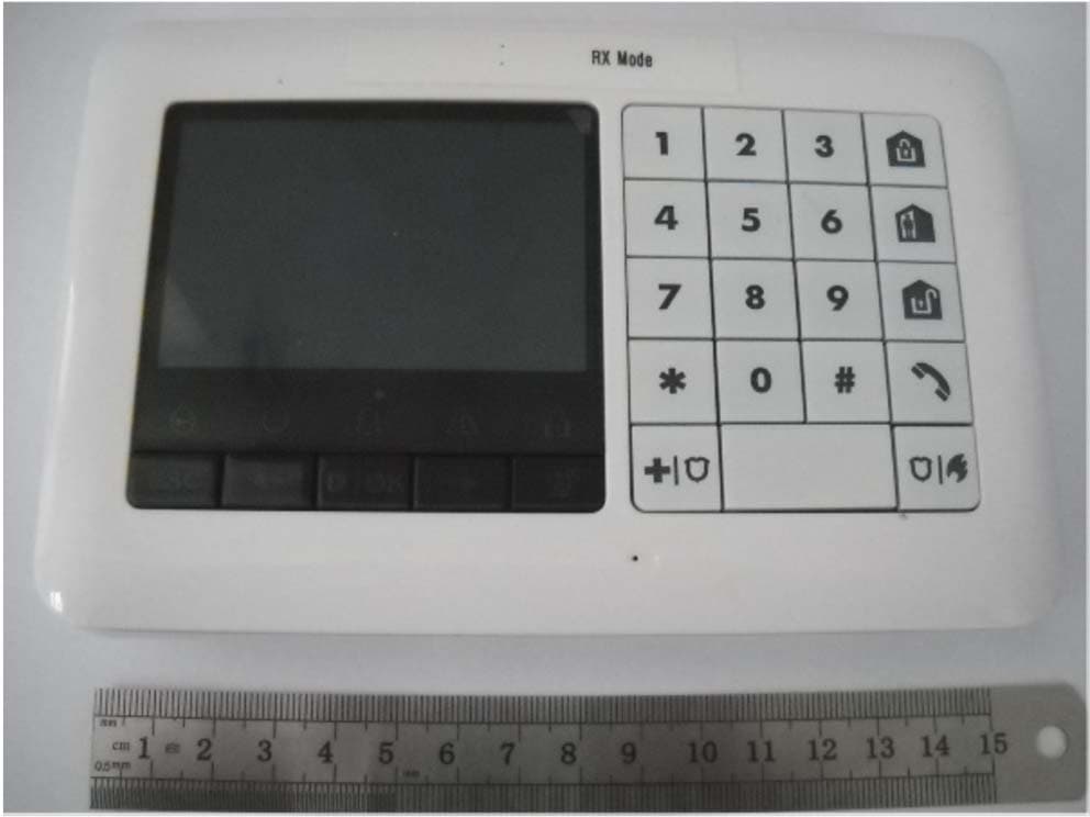
Click to zoom
Application Details
- Equipment Class
- DCD - Part 15 Low Power Transmitter Below 1705 kHz
- Date of Grant
- Sep 29, 2014
- Application Purpose
- Original Equipment
- Date of Application
- Sep 29, 2014
- Equipment Note
- Advanced two-way keypad
- Frequency Range
- 0.11750000 - 0.11750000
- Company
- Visonic Ltd.
- Country
- Israel
Documents & Files
Document Text
Text extracted from the exhibit documents filed with the FCC. Open a document above to read the original.
Users Manual
D-304269 KP-250 PG2 User’s Guide 1 KP-250 PG2 Advanced Two-Way Keypad User’s Guide Table of Contents 1. Introduction ................................................................................................................................................................. 3 2. Additional System Features ........................................................................................................................................ 3 Partitioning .............................................................................................................................................................. 3 Screen Saver .......................................................................................................................................................... 3 Proximity Tags ........................................................................................................................................................ 3 Users and Codes .................................................................................................................................................... 3 Speech & Sound Cont. Push-buttons ..................................................................................................................... 3 Voice ON/OFF ........................................................................................................................................................ 4 Recording a Message ............................................................................................................................................. 4 Message Playback .................................................................................................................................................. 5 3. Arming and Disarming the System ............................................................................................................................. 6 Basic Arming and Disarming................................................................................................................................... 6 Special Arming & Disarming Options ...................................................................................................................... 7 Initiating Alarms .................................................................................................................................................... 10 4. System Status and Indications ................................................................................................................................. 13 LCD Display and General Audible Indicators ........................................................................................................ 13 Arming Indications ................................................................................................................................................ 13 General Indications ............................................................................................................................................... 14 Alarm Indication Siren ........................................................................................................................................... 15 5. Reviewing Troubles and Alarm Memory ................................................................................................................... 16 Alarm & Tamper Memory Indication ..................................................................................................................... 16 Clearing the Memory Indication ............................................................................................................................ 16 Troubles ................................................................................................................................................................ 16 GSM/GPRS Status Indications ............................................................................................................................. 17 Trouble Indications ............................................................................................................................................... 18 6. System Configuration ............................................................................................................................................... 19 A.1 Entering the User Settings Menu & Selecting a Setting Option ...................................................................... 19 A.2 Returning to the Previous Step or Exiting the USER SETTINGS Menu ......................................................... 21 A.3 Buttons used for Navigation & Setting ............................................................................................................ 22 B.1 Setting the Zone Bypass Scheme .................................................................................................................. 22 B.2 Reviewing the Zone Bypass Scheme ............................................................................................................. 24 B.3 Recalling the Zone Bypass Scheme ............................................................................................................... 24 B.4 Programming User Codes .............................................................................................................................. 25 B.5 Programming the Duress Code ...................................................................................................................... 27 B.6 Add / Delete Proximity Tags ........................................................................................................................... 28 B.7 Add / Delete Keyfob Transmitters ................................................................................................................... 30 B.8 Setting the Time & Time Format .........................................................................…
Text truncated - open the document above for the full version.
Cover Letter(s)
Rev 11/20/07 To: Timco Engineering, Inc. To Whom It May Concern We the undersigned, hereby authorize Mr. Michael Nikishin of Hermon Laboratories to act on behalf of Visonic Ltd. in all manners relating to application for certification of FCC ID:WP3KP250PG2, IC:1467C-KP250PG2. Any and all acts carried out by Hermon Laboratories, on our behalf shall have the same legal authority as acts of our own. This authorization is valid until further written notice from Visonic Ltd. Sincerely, Arik Elshtein
Cover Letter(s)
Rev 11/20/07 Federal Communications Commission Authorization and Evaluation Division Confidentiality Request regarding application for certification of FCC ID:WP3KP250PG2. Pursuant to Sections 0.457 and 0.459 of the Commission’s Rules, we hereby request confidential treatment of information accompanying this application as outlined below: Exhibit Type File Name Block diagram KP-250_BlkDia Schematic diagram KP-250_Schem Operational description KP-250_OpDes The above materials contain trade secrets and proprietary information not customarily released to the public. The public disclosure of these materials may be harmful to the applicant and provide unjustified benefits to its competitors. The applicant understands that pursuant to Section 0.457 of the Rules, disclosure of this application and all accompanying documentation will not be made before the date of the Grant for this application. Sincerely, Arik Elshtein
External Photos
Visonic Ltd. FCC ID:WP3KP250PG2 IC:1467C-KP250PG2 Page 1 of 4 EXTERNAL PHOTOGRAPHS This document contains 3 photographs Visonic Ltd. FCC ID:WP3KP250PG2 IC:1467C-KP250PG2 Page 2 of 4 Photograph No.1 Two-way keypad KP-250 PG2 front view Visonic Ltd. FCC ID:WP3KP250PG2 IC:1467C-KP250PG2 Page 3 of 4 Photograph No.2 Two-way keypad KP-250 PG2 rear side view Visonic Ltd. FCC ID:WP3KP250PG2 IC:1467C-KP250PG2 Page 4 of 4 Photograph No.3 Two-way keypad KP-250 PG2 rear side view without bracket
ID Label/Location Info
Visonic Ltd. FCC ID:WP3KP250PG2 IC:1467C-KP250PG2 Page 1 of 1 Label Label location Label with FCC ID:WP3KP250PG2 and IC:1467C-KP250PG2 will be located at the rear side panel of the keypad. The statement according to FCC part 15 §15.19(a)(3) is placed in Installer’s Guide, page 88 (Application exhibit KP-250_UserMan).
Internal Photos
Visonic Ltd. FCC ID:WP3KP250PG2 IC:1467C-KP250PG2 Page 1 of 7 INTERNAL PHOTOGRAPHS This document contains 6 photographs Visonic Ltd. FCC ID:WP3KP250PG2 IC:1467C-KP250PG2 Page 2 of 7 Photograph No.1 Two-way keypad KP-250 PG2 internal view Visonic Ltd. FCC ID:WP3KP250PG2 IC:1467C-KP250PG2 Page 3 of 7 Photograph No.2 Two-way keypad PCB front view Visonic Ltd. FCC ID:WP3KP250PG2 IC:1467C-KP250PG2 Page 4 of 7 Photograph No.3 Two-way keypad PCB rear side view Visonic Ltd. FCC ID:WP3KP250PG2 IC:1467C-KP250PG2 Page 5 of 7 Photograph No.4 Two-way keypad RF module front view Visonic Ltd. FCC ID:WP3KP250PG2 IC:1467C-KP250PG2 Page 6 of 7 Photograph No.5 Two-way keypad RF module second side view Visonic Ltd. FCC ID:WP3KP250PG2 IC:1467C-KP250PG2 Page 7 of 7 Photograph No.6 RFID reader close view
Test Report
Hermon Laboratories Ltd. Harakevet Industrial Zone, Binyamina 30500, Israel Tel. +972-4-6288001 Fax. +972-4-6288277 E-mail: [email protected] Page 1 of 27 Report ID: VISRAD_FCC.23967_15.209.docx Date of Issue: 2-Sep-14 ELECTRICAL TESTING 0839.01 TEST REPORT ACCORDING TO: FCC 47CFR part 15 subpart C § 15.209 and RSS-210 issue 8 section 2.5.1 FOR: Visonic Ltd. RFID reader of advanced two-way keypad Model: KP-250 PG2 FCC ID:WP3KP250PG2 IC:1467C-KP250PG2 This report is in conformity with ISO/ IEC 17025. The "A2LA Accredited" symbol endorsement applies only to the tests and calibrations that are listed in the scope of Hermon Laboratories accreditation. The test results relate only to the items tested. This test report shall not be reproduced in any form except in full with the written approval of Hermon Laboratories Ltd. Report ID: VISRAD_FCC.23967_15.209.docx Date of Issue: 2-Sep-14 Page 2 of 27 Table of contents 1 Applicant information ..................................................................................................................................................... 3 2 Equipment under test attributes .................................................................................................................................... 3 3 Manufacturer information .............................................................................................................................................. 3 4 Test details .................................................................................................................................................................... 3 5 Tests summary .............................................................................................................................................................. 4 6 EUT description ............................................................................................................................................................. 5 6.1 General information ....................................................................................................................................................... 5 6.2 Ports and lines .............................................................................................................................................................. 5 6.3 Test configuration .......................................................................................................................................................... 5 6.4 Changes made in the EUT ............................................................................................................................................ 5 7 Transmitter tests according to 47CFR part 15 subpart C and RSS-210 requirements ................................................. 6 7.1 Field strength of emissions ............................................................................................................................................ 6 7.2 Antenna requirements ................................................................................................................................................. 14 7.3 Occupied bandwidth test ............................................................................................................................................. 15 8 APPENDIX A Test equipment and ancillaries used for tests ....................................................................................... 18 9 APPENDIX B Measurement uncertainties ................................................................................................................... 19 10 APPENDIX C Test laboratory description ................................................................................................................... 20 11 APPENDIX D Specification references ....................................................................................................................... 20 12 APPENDIX E Test equipment correction factors ......................................................................................................... 21 13 APPENDIX F Abbreviations and acronyms ................................................................................................................. 27 Report ID: VISRAD_FCC.23967_15.209.docx Date of Issue: 2-Sep-14 Page 3 of 27 1 Applicant information Client name: Visonic Ltd. Address: 24 Habarzel street, Tel Aviv 69710, Israel Telephone: +972 3 645 6714 Fax: +972 3645 6788 E-mail: [email protected] Contact name: Mr. Arik Elshtein 2 Equipment under test attributes Product name: RFID reader of Advanced Two-Way Keypad Product type: Transceiver Model(s): KP-250 PG2 Cataloque number: 102679 Hardware version: 90-205104 Software release: JS-702451 Receipt date 7-Aug-14 3 Manufacturer information Manufacturer name: Visonic Ltd. Address: 24 Habarzel street, Tel Aviv 69710, Israel Telephone: +972 3 645 6714 Fax: +972 3645 6788 E-Mail: [email protected] Contact name: Mr. Arik Elshtein 4 Test details Project ID: 23967 Location: Hermon Laboratories Ltd. Harakevet Industrial Zone, Binyamina 30500, Israel Test started: 7-Aug-14 Test completed: 21-Aug-14 Test specification(s): FCC 47CFR part 15, subpart C, §15.209; RSS-210 issue 8 section 2.5.1, RSS-Gen issue 3 Table 6 Report ID: VISRAD_FCC.23967_15.209.docx Date of Issue: 2-Sep-14 Page 4 of 27 5 Tests summary Test Status Transmitter characteristics Section 15.209 / RSS-Gen section 7.2.5, Field strength of emissions Pass Section 15.203 / RSS-Gen, Section 7.1.2, Antenna requirements Pass RSS-Gen, Section 4.6.1, Occupied bandwidth Tested Testing was completed against all relevant requirements of the test standard. The results obtained indicate that the product under test complies in full with the requirements tested. The test results relate only to the items tested. Pass/ fail decision was based on nominal values. Name and Title Date Signature Tested by: Mr. V. Einem, test engineer Augus…
Text truncated - open the document above for the full version.
Test Setup Photos
Visonic Ltd. FCC ID:WP3KP250PG2 IC:1467C-KP250PG2 Page 1 of 9 SETUP PHOTOGRAPHS This document contains 8 photographs Visonic Ltd. FCC ID:WP3KP250PG2 IC:1467C-KP250PG2 Page 2 of 9 Photograph No.1 Setup for spurious emission field strength measurements in the anechoic chamber below 30 MHz Visonic Ltd. FCC ID:WP3KP250PG2 IC:1467C-KP250PG2 Page 3 of 9 Photograph No.2 Setup for carrier field strength, spurious emission field strength measurements in the anechoic chamber in 30 – 1000 MHz range Visonic Ltd. FCC ID:WP3KP250PG2 IC:1467C-KP250PG2 Page 4 of 9 Photograph No.3 Setup for spurious emission field strength measurements in the anechoic chamber above 1000 MHz range Visonic Ltd. FCC ID:WP3KP250PG2 IC:1467C-KP250PG2 Page 5 of 9 Photograph No.4 Setup for spurious emission field strength measurements in the anechoic chamber, EUT close view Visonic Ltd. FCC ID:WP3KP250PG2 IC:1467C-KP250PG2 Page 6 of 9 Photograph No.5 Setup for OBW measurements Visonic Ltd. FCC ID:WP3KP250PG2 IC:1467C-KP250PG2 Page 7 of 9 Photograph No.6 Setup for band edge emissions and hopping parameters measurements Visonic Ltd. FCC ID:WP3KP250PG2 IC:1467C-KP250PG2 Page 8 of 9 Photograph No.7 Setup for conducted emission measurements on the AC power lines Visonic Ltd. FCC ID:WP3KP250PG2 IC:1467C-KP250PG2 Page 9 of 9 Photograph No.8 Setup for conducted emission measurements on the AC power lines
Contact Information
Applicant
Zuri Rubin(Certification Manager)
Test Firm
Hermon Laboratories Ltd.Alexander Usoskin
Technical Specifications
| # | Rule Parts | Frequency Range | Power Output |
|---|---|---|---|
| 1 | 15C | 0.1175 MHz - 0.1175 MHz | - |
Other Applications from Visonic Ltd.
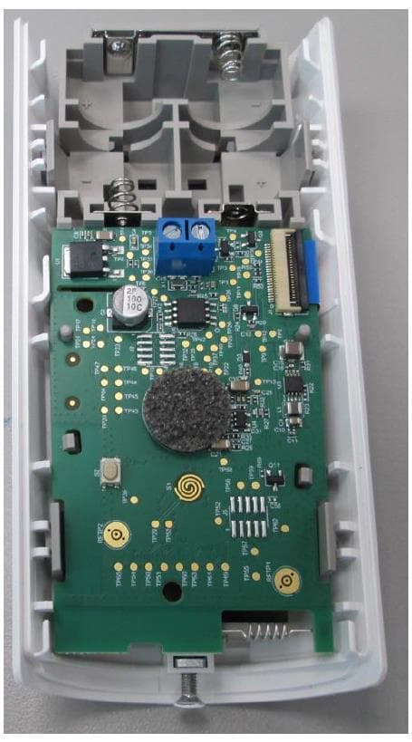
WP3NEXTCAMPGP
Dec 21, 2023Wireless Motion detector with integrated camera
Equipment Class
DSS - Part 15 Spread Spectrum Transmitter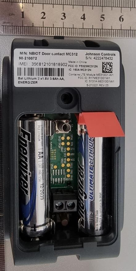
WP3RP600PGP
May 16, 2023Wireless Repeater for PowerG Communications
Equipment Class
DSS - Part 15 Spread Spectrum Transmitter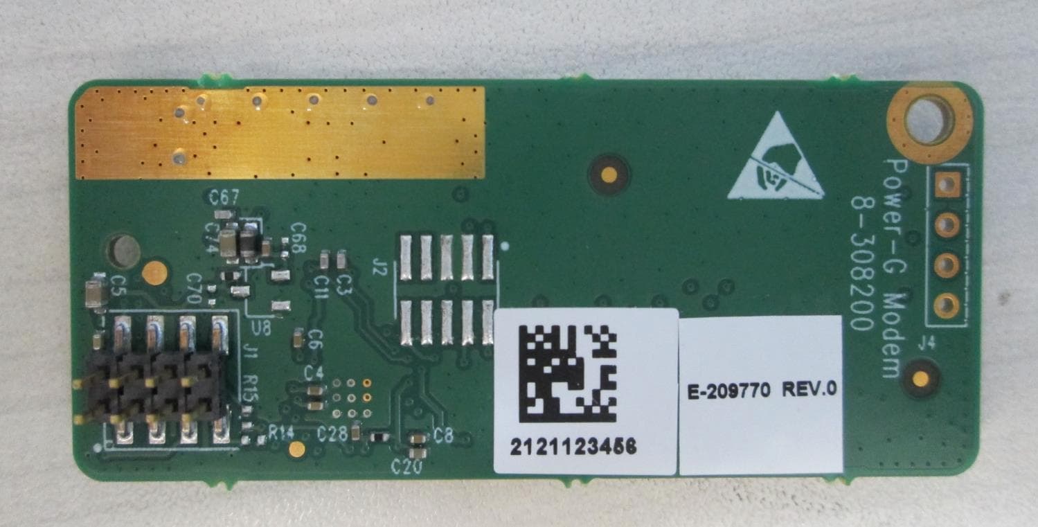
WP3PGMODIQREM
Jun 02, 2021Power-G Modem iQ Remote
Equipment Class
DSS - Part 15 Spread Spectrum Transmitter
WP3SD304EPG2
Jan 03, 2021PowerG Wireless Shock Detector
Equipment Class
DSS - Part 15 Spread Spectrum Transmitter
WP3MP843
Jun 30, 2020PIR detector ZigBee
Equipment Class
DTS - Digital Transmission System