WP3MC332WIRELESS CURTAIN-TYPE POWERCODE INFARED DETECTOR
Visonic Ltd.
Click to zoom
Application Details
- Equipment Class
- DSC - Part 15 Security/Remote Control Transmitter
- Date of Grant
- Jan 26, 2012
- Application Purpose
- Original Equipment
- Date of Application
- Jan 26, 2012
- Equipment Note
- WIRELESS CURTAIN-TYPE POWERCODE INFARED DETECTOR
- Frequency Range
- 315.00000000 - 315.00000000
- Company
- Visonic Ltd.
- Country
- Israel
Documents & Files
Document Text
Text extracted from the exhibit documents filed with the FCC. Open a document above to read the original.
Users Manual
D-3030691 MCT-330/MCT-332 English MagneticContactTransmitter Installation Instructions Español Contacto Magnético InalámbricoInstrucciones de Instalación Portuguese Transmissor de Contacto MagnéticoInstruções de Instalação or/ o/ ou MCT-330 or/ o/ ou or/ o/ ou or/ o/ ou MCT-332 Fig. 1- Options / Opciones / Opções ENGLISH 1. INTRODUCTION TheMCT-330/MCT-332 is a fully supervised, PowerCode magnetic contact transmitter, for use with PowerCode products. The transmitter includes a built-in reed switch (that opens upon removal of a magnet placed near it). MCT-332 is similar toMCT-330 but has2 internal reed switches and 2 external magnets, for use with a door/windowwith 2 movable parts. One of the MCT-332 reed switches / magnets can be disabled– for use with door/windowthat has 1 movable part (seeFig. 1). The magnet switch has a unique 24-bit PowerCode ID, selected in the factory, from over 16 million possible code combinations. Since messages transmitted by theMCT-330/MCT-332 might collide with transmissions from other PowerCode transmitters, a "smart" anti- collision transmission sequence is used. TheMCT-330/MCT-332 tamper switch is activated when the cover is removed or when the detector is removed from the wall. A periodic supervision message is transmitted automatically. The target receiver is thus informed, at regular intervals, of the unit’s active participation in the system. An LED lights whenever alarm or tamper events are reported. The LED light can be disabled if desired. The LED does not light while a supervision message is being transmitted. Operating power is obtained from an on-board 3 V Lithium battery. When the battery voltage is low, a “low battery” message is sent to the receiver. 2.SPECIFICATIONS Frequency (MHz): 315, 433.92, 868.95, 869.2125or according to local requirements (UL has only investigated at 315 MHz). Transmitter's ID Code:24-bit digital word,over 16 million combinations, pulse width modulation. Overall Message Length: 36 bits Power Source: 3 V Lithium CR-123 type battery, Panasonic, Sanyo or GP only. Caution!Risk of explosion if battery is replaced by an incorrect type. Dispose of used batteries according to the manufacturer's instructions. Battery Life Expectancy:6 years (for typical use) Battery Supervision: Automatic transmission of battery condition data as part of any status report. Operating Temperature:-10C to 55C (14F to 131F). Dimensions:51 x 30 x 21 mm (2 x 1-3/16 x 13/16 in.) Weight (without battery): 30g (1.05 oz) Standards: USA (315 MHz):CFR47 part 15 (FCC)UL 634, ULC C634 Europe (433.92, 868.95, 869.2125):ETSI EN 301 489-3 V1.4.1: (2002- 08) , EN 50130-4:( 95) & A1 : (98) & A2: (03) EN 300 220-2 V2.1.2 :2007, EN 300 220-1 V2.1.1 :2006 EN 60950-1: 2006, EN 50130-5: 1998EN 50131-1 :2007, CLC/TS 50131-2-6:2004 Note:If triggered more than 218 times every day of the year, the product will not comply with the Belgium standards. This device complies with Part 15 of the FCC Rules and RSS-210 of Industry and Science Canada. Operation is subject to the following two conditions: (1) This device may not cause harmful interference, and (2) this device must accept any interference received, including interference that may cause undesired operation. This device complies with the essential requirements and provisions of Directive 1999/5/EC of the European Parliament and of the Council of 9 March 1999 on radio and telecommunications terminal equipment. This device complies with Industry Canada licence-exempt RSS standard(s). Operation is subject to the following two conditions: (1) this device may not cause harmful interference, and (2) thisdevice must accept any interference, including interference that may cause undesired operation of the device. Le présent appareil est conforme aux CNR d'Industrie Canada applicablesaux appareils radio exempts de licence. L'exploitation est autorisée aux deux conditions suivantes : (1) l'appareil ne doit pas produire de brouillage, et (2) l'utilisateur de l'appareil doit accepter tout brouillage radioélectrique subi, même si le brouillage est susceptible d'en compromettre le fonctionnement. 3.GENERAL INFORMATION It is highly recommended to attach the transmitter to the top of the door/window on the fixed frame and the magnet to the movable part (door or window). Make sure that the magnet is located not more than 6 mm (0.25 in.) from the transmitter. Note:Once the cover is removed, a tamper message is transmitted to the receiver. Subsequent removal of the battery prevents transmission of "TAMPER RESTORE", leaving the receiver inpermanent alert. To avoid this, during the enrolling process, press the tamper switch(fig.4)while you remove the battery. 4.MOUNTING The transmitter should be mounted on the fixed surface and the magnet on the moving surface (seeFigure2). 4.1 Transmitter Mounting(see Figure3) 4.2 Magnet Mounting(see Figure1 &5) MCT-332with 1 magnetand MCT-330:The magnetshould be installed at the centerof theleftside or at the center of the right side. MCT332 with 2 magnets:One magnetshould be installed at thecenter (left or right side) andthe second magnetshould be installedat the bottom side (near the opening slot, left or right side),NOT AT THE TOP SIDE! 5. Instructions only for MCT-332 thatuses only 1 reed switch & magnet The MCT-332 includes 2 internal read switches and 2 external magnets. If it is desired to use only 1 reed switch and 1 magnet only (one door/window movable part), the internal reed switch#2 and magnet #2 must be disabled.For this reason set the MAGNET 2 switch to OFF position (see figure 4). 6.TEST A.Insert the battery between the battery clips, at the correct polarity. For proper operation, only Lithium Thionyl Chloride battery (Panasonic, Sanyo or GP type CR123) should be used. Caution: Risk of explosion if battery is replaced by an incorrect type. Dispose used battery according to manufacturer's instructions. B.Press the tamper switch(see figure 4)once and release it. Note: Since the cover is r…
Text truncated - open the document above for the full version.
Cover Letter(s)
Dec 15 2011 Letter of individual Authorization to sign Form 731 To: Timco Engineering Inc. To Whom It May Concern We hereby authorize Shaike Raz of ITL as an authorized individual to sign forform 731on behalf of Visonic Ltdfor theFCC ID:WP3MC332 application. Thank you, Arick Elshtein
Cover Letter(s)
Dec 15 2011 attn:Reviewing Engineer Federal Communications Commission 7435 Oakland Mills Road Columbia, MD 21046 To Whom It May Concern: TheWireless Curtain-Type PowerCode Infrared Detector,FCC ID:WP3MC332and labelis so small that it cannot include the statement specified in FCC Part 15 Sub-part A, Section 15.19 (a) (3) “This device complies with Part 15 of the FCC Rules. Operation is subject to the following two conditions: (1)This device may not cause harmful interference and (2)This device must accept any interference received, including interference that may cause undesired operation." Due to this reason, we are using the provisions of Part 15 Sub-part A, Section 15.19 (a) (5) and this statement appears in a prominent location in the user manual. Please contact me if there is any information you may need. Thank you, Arick Elshtein
Cover Letter(s)
Date:Dec 15 2011 Federal Communications Commission Authorization and Evaluation Division Subject: Confidentiality Request regarding application for certification of FCC ID:WP3MC332 DearSirs Pursuant to Sections 0.457 and 0.459 of the Commission’s Rules, we hereby request confidential treatment of information accompanying this application as outlined below: CONF APPENDIXMCT-332(315) Schem.pdf CONF APPENDIXMCT-332(315)PartsLst.xls CONF APPENDIXMCT-332(315)BlkDia.pdf The above materials contain trade secrets and proprietary information not customarily released to the public. The public disclosure of these materials may be harmful to the applicant and provide unjustified benefits to its competitors. The applicant understands that pursuant to Section 0.457 of the Rules, disclosure of this application and all accompanying documentation will not be made before the date of the Grant for this application. Sincerely, Arick Elshtein
Operational Description
Product Description MCT-332 (315) FCCID: WP3MC332 The MCT-330/MCT-332 is a fully supervised, PowerCode magnetic contact transmitter, for use with PowerCode products. The transmitter includes a built- in reed switch (that opens upon removal of a magnet placed near it). MCT-332 is similar to MCT-330 but has 2 internal reed switches and 2 external magnets, for use with a door/window with 2 movable parts. One of the MCT-332 reed switches / magnets can be disabled– for use with door/window that has 1 movable part. The magnet switch has a unique 24-bit PowerCode ID, selected in the factory, from over 16 million possible code combinations. Since messages transmitted by the MCT-330/MCT-332 might collide with transmissions from other PowerCode transmitters, a "smart" anti- collision transmission sequence is used. The MCT-330/MCT-332 tamper switch is activated when the cover is removed or when the detector is removed from the wall. A periodic supervision message is transmitted automatically. The target receiver is thus informed, at regular intervals, of the unit’s active participation in the system. An LED lights whenever alarm or tamper events are reported. The LED light can be disabled if desired. The LED does not light while a supervision message is being transmitted. Operating power is obtained from an on-board 3 V Lithium battery. When the battery voltage is low, a “low battery” message is sent to the receiver. The E.U.T operates at 315 MHz.
Parts List/Tune Up Info
Date:Dec15 2011 To Whom It May Concern I hereby declare that there is no tune-up procedure for: FCC ID: WP3MC332 Thank you, Arick Elshtein
Test Report
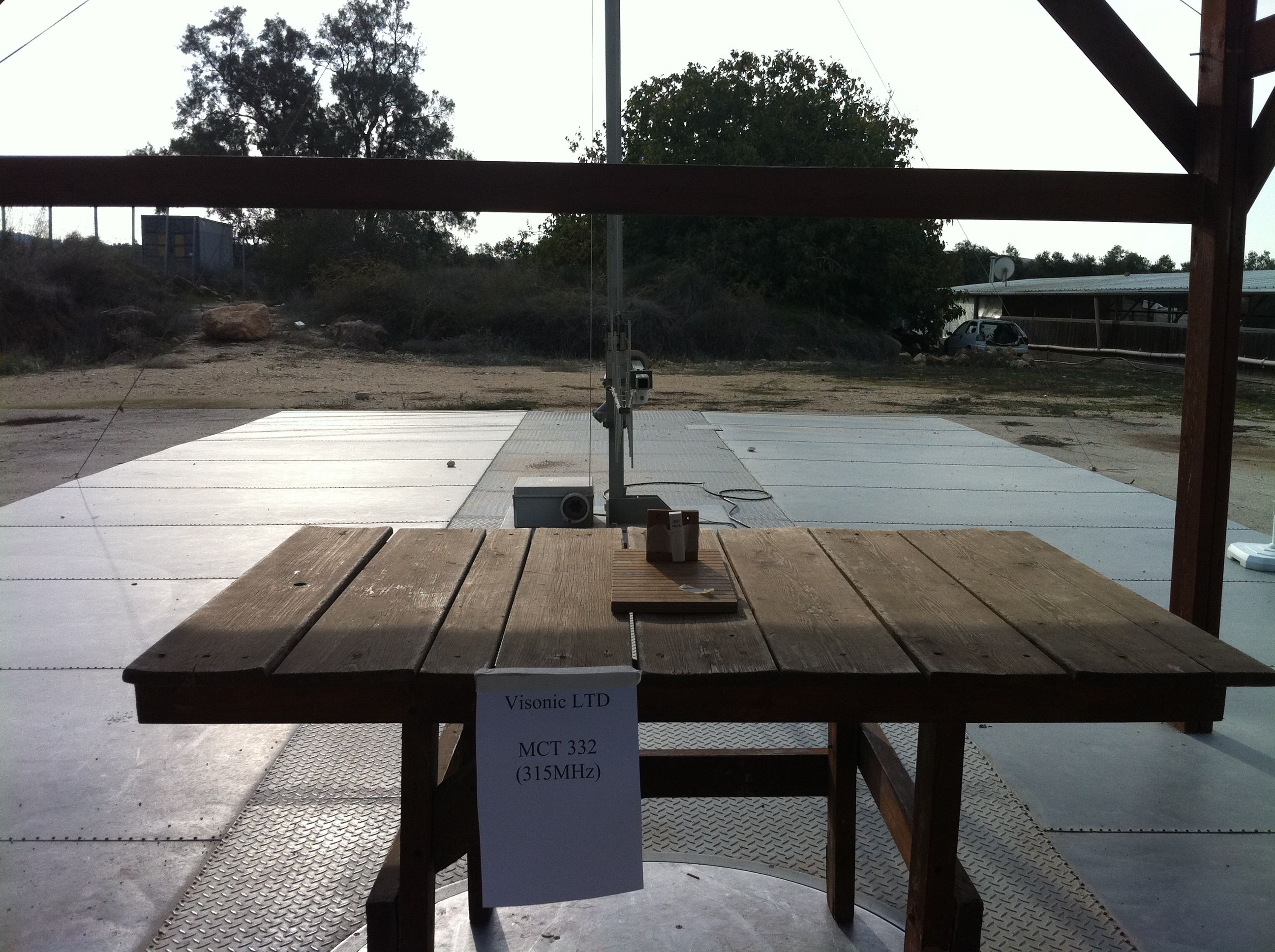
Test Report E108733.00 Visonic Ltd. Page 1 of 43 FCC ACC M Ver 1.1 05Mayl 2000 DATE: 10 January 2012 I.T.L. (PRODUCT TESTING) LTD. FCC Radio Test Report for Visonic Ltd. Equipment under test: PowerCode Magnetic Contact Transmitter MCT-332 (315 MHz) MCT-330 (315 MHz)* * See customer’s declaration on page 6. Written by: _____________________________ D. Shidlowsky, Documentation Approved by: _____________________________ A. Moses, Test Engineer Approved by: _____________________________ I. Raz, EMC Laboratory Manager This report must not be reproduced, except in full, without the written permission of I.T.L. (Product Testing) Ltd. This report relates only to items tested. Test Report E108733.00 Visonic Ltd. Page 2 of 43 FCC ACC M Ver 1.1 05Mayl 2000 Measurement/Technical Report for Visonic Ltd. PowerCode Magnetic Contact Transmitter MCT-332 (315 MHz) MCT-330 (315 MHz)* * See customer’s declaration on page 6. FCC ID: WP3MC332 IC: 1467C-MC332 This report concerns: Original Grant: x Class I change: Class II change: Equipment type: Part 15 Security/Remote Control Transceiver 47CFR15 Section 15231 (a-d) Measurement procedure used is ANSI C63.4-2003. Application for Certification Applicant for this device: prepared by: (different from "prepared by") Ishaihou Raz Arik Elshtein ITL (Product Testing) Ltd. Visonic Ltd. Kfar Bin Nun 24 Habarzel St. D.N. Shimshon 99780 Tel-Aviv 69710 Israel Israel e-mail [email protected] Tel: +972-3 -645-6789 Fax: +972-3- 645-6788 e-mail: [email protected] Test Report E108733.00 Visonic Ltd. Page 3 of 43 FCC ACC M Ver 1.1 05Mayl 2000 TABLE OF CONTENTS 1. GENERAL INFORMATION ------------------------------------------------------------------------------- 4 1.1 Administrative Information ................................................................................. 4 1.2 List of Accreditations ......................................................................................... 6 1.3 Product Description ........................................................................................... 7 1.4 Test Methodology .............................................................................................. 7 1.5 Test Facility ....................................................................................................... 7 1.6 Measurement Uncertainty ................................................................................. 7 2. SYSTEM TEST CONFIGURATION --------------------------------------------------------------------- 8 2.1 Justification ........................................................................................................ 8 2.2 Special Accessories .......................................................................................... 8 2.3 Equipment Modifications ................................................................................... 8 2.4 Configuration of Tested System ........................................................................ 8 3. RADIATED MEASUREMENT TEST SET-UP PHOTOS------------------------------------------- 9 4. AVERAGE FACTOR CALCULATION ----------------------------------------------------------------- 10 1.1 Test Instrumentation Used .............................................................................. 14 5. PERIODIC OPERATION ---------------------------------------------------------------------------------- 15 5.1 Specification .................................................................................................... 15 5.2 Requirements .................................................................................................. 15 5.3 Results ............................................................................................................. 15 5.1 Test Instrumentation Used .............................................................................. 20 6. FIELD STRENGTH OF FUNDAMENTAL ------------------------------------------------------------ 21 6.1 Test Specification ............................................................................................ 21 6.2 Test Procedure ................................................................................................ 21 6.3 Measured Data ................................................................................................ 21 6.4 Test Instrumentation Used, Field Strength of Fundamental ............................ 25 7. RADIATED EMISSION, 9 KHZ – 30 MHZ ------------------------------------------------------------ 26 7.1 Test Specification ............................................................................................ 26 7.2 Test Procedure ................................................................................................ 26 7.3 Measured Data ................................................................................................ 26 1.2 Test Instrumentation Used, Radiated Measurements ..................................... 27 7.4 Field Strength Calculation ............................................................................... 27 8. SPURIOUS RADIATED EMISSION-------------------------------------------------------------------- 28 8.1 Test Specification ............................................................................................ 28 8.2 Test Procedure ................................................................................................ 28 8.3 Test Data ......................................................................................................... 29 8.4 Test Instrumentation Used, Radiated Measurements ..................................... 31 9. BANDWIDTH ------------------------------------------------------------------------------------------------ 32 9.1 Test procedure ................................................................................................ 32 9.2 Results table .................................................................................................... 33 9.3 Test Equipmen…
Text truncated - open the document above for the full version.
Contact Information
Applicant
Zuri Rubin(Certification Manager)
Test Firm
Israel Testing LaboratoriesIIan Cohen
Technical Specifications
| # | Rule Parts | Frequency Range | Power Output |
|---|---|---|---|
| 1 | 15.231 | 315 MHz - 315 MHz | - |
Other Applications from Visonic Ltd.
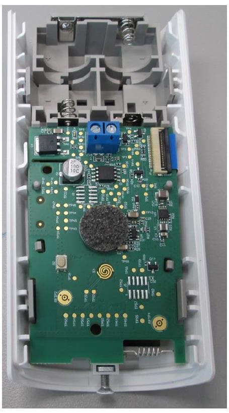
WP3NEXTCAMPGP
Dec 21, 2023Wireless Motion detector with integrated camera
Equipment Class
DSS - Part 15 Spread Spectrum Transmitter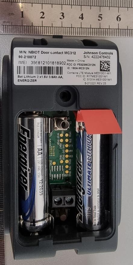
WP3RP600PGP
May 16, 2023Wireless Repeater for PowerG Communications
Equipment Class
DSS - Part 15 Spread Spectrum Transmitter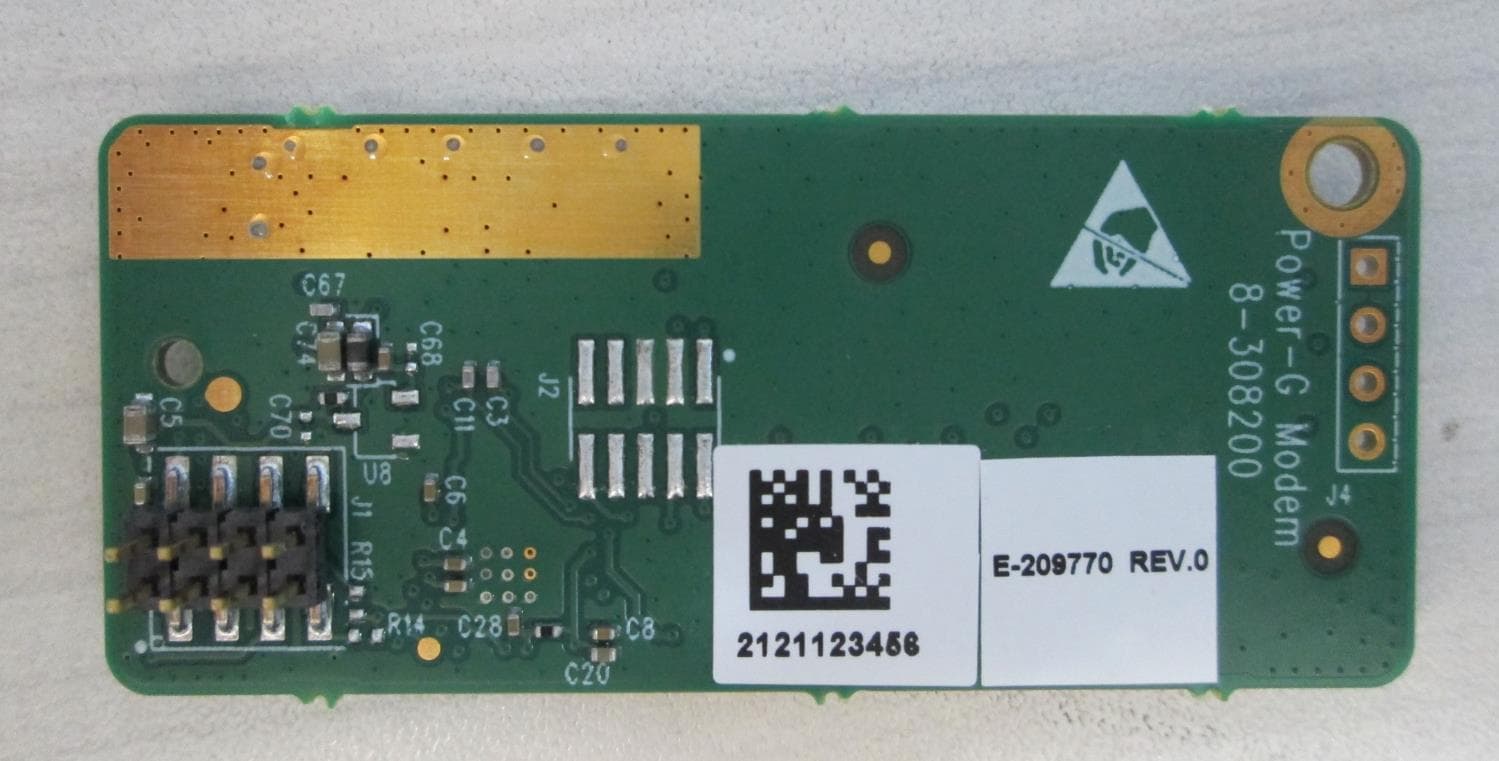
WP3PGMODIQREM
Jun 02, 2021Power-G Modem iQ Remote
Equipment Class
DSS - Part 15 Spread Spectrum Transmitter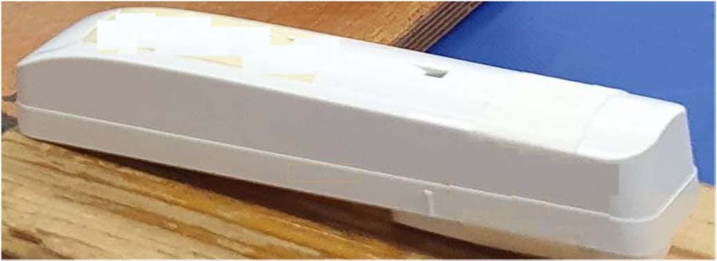
WP3SD304EPG2
Jan 03, 2021PowerG Wireless Shock Detector
Equipment Class
DSS - Part 15 Spread Spectrum Transmitter
WP3MP843
Jun 30, 2020PIR detector ZigBee
Equipment Class
DTS - Digital Transmission System