WP3MCT212GSLAHANDHELD TRANSMITTER FOR AMBER GS/ AMBER LINK (315)
Visonic Ltd.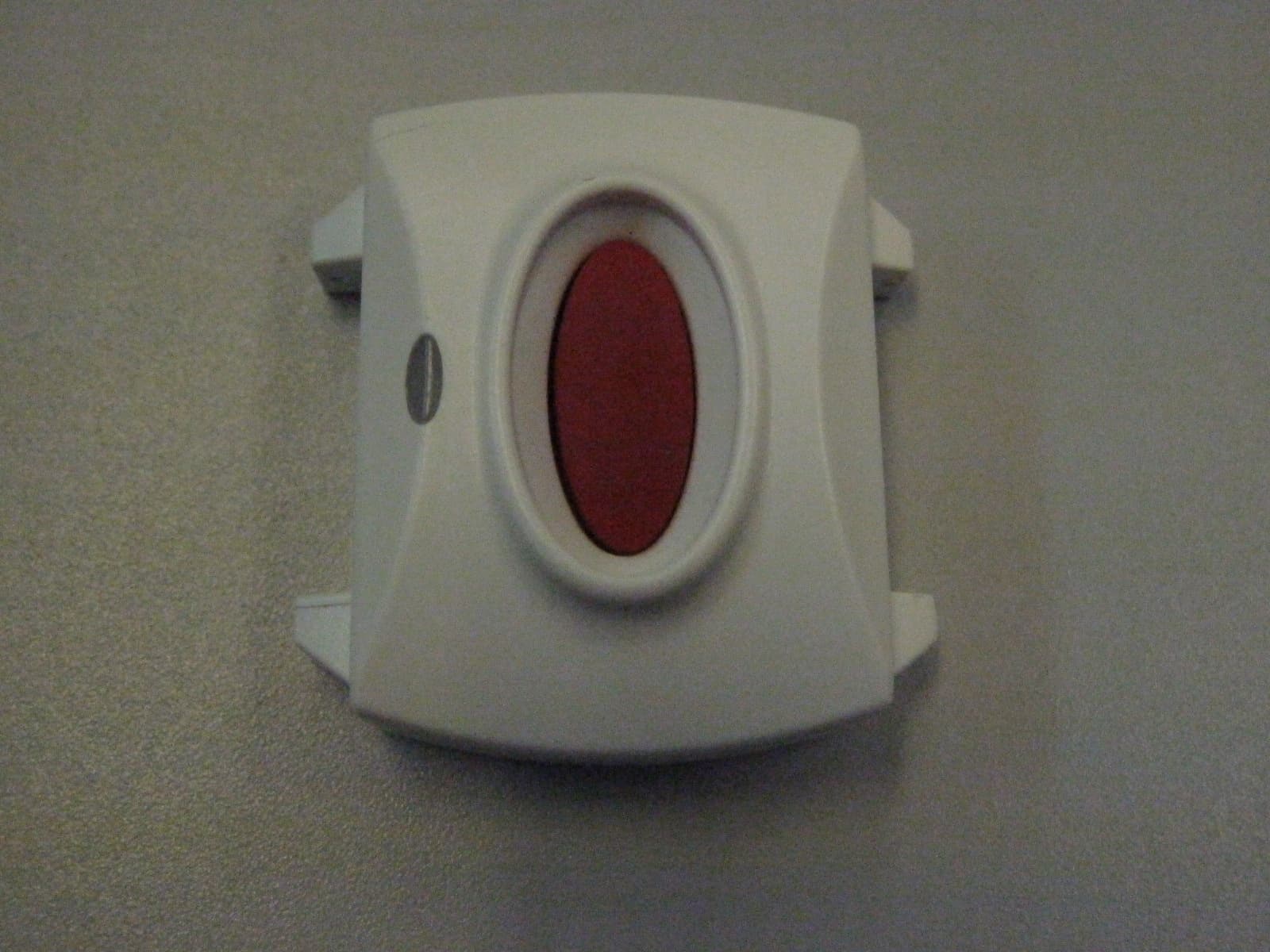
Click to zoom
Application Details
- Equipment Class
- DSC - Part 15 Security/Remote Control Transmitter
- Date of Grant
- Feb 21, 2011
- Application Purpose
- Original Equipment
- Date of Application
- Feb 17, 2011
- Equipment Note
- HANDHELD TRANSMITTER FOR AMBER GS/ AMBER LINK (315)
- Frequency Range
- 315.00000000 - 315.00000000
- Company
- Visonic Ltd.
- Country
- Israel
Documents & Files
Document Text
Text extracted from the exhibit documents filed with the FCC. Open a document above to read the original.
Users Manual
D-302914 1 MCT-212 GS GB/US: LED indicator SP: Indicador LED PT: Indicador LED GB/US: Fastener SP: Seguro PT: Segurança GB/US: Transmit Button SP: Botón de transmission PT: Botão de Transmissão GB/US: Loop SP: Hebilla PT: Presilha MCT-212 GS with Wrist Band / AMBER con Pulsera para Muñeca / AMBER com faixa para o pulso GB/US: Safety release mechanism SP: Mecanismo de liberación de seguridad PT: Mecanismo de liberação da segurança GB/US: Neck cord SP: Colgante para el cuello PT: Cordão para o pescoço GB/US: Fastener SP: Seguro PT: Segurança MCT-212 GS with Neck Strap / con correa para el cuello / AMBER com cinta para o pescoço English Waterproof PowerCode Wrist Transm uide itter – User G Español Transmisor Impermeable de Pulsera PowerCod Guía de Usuario e - Portuguese Transmissor Impermeável de Pulso Acionado a Código – Guia do Usuário ENGLISH (GB/US) 1. INTRODUCTION The MCT-212 GS is a miniature waterproof transmitter, designed for home health care signaling. In the event of an emergency, help can be summoned at the press of the C. ainst faults. cy inations. tteries according to the manufacturer's ort to the transmitter button. All MCT-212 GS units are supplied with a wrist band and neck strap. They can be worn on the wrist or around the neck. The LED lights during a transmission to indicate a good battery. If the LED flashes during a transmission, this means that the battery is low and must be replaced immediately. Anytime the MCT-212 GS is pressed when the battery is low, a trouble signal will automatically be sent to the Base Unit. To alert you of the trouble, a red LED will flash and a trouble message will appear on the display of the Base Unit. All troubles are reported to the Monitoring Center. The transmitter case is waterproof, hermetically sealed (no screws) and therefore disposable. Do not attempt to open the transmitter case or replace the battery; such action will void the warranty. ENROLLMENT 2. TEST, MAINTENANCE & 2.1 Enrolling Transmitters In order for a transmitter to function, its ID must be enrolled into the Base Unit. The Transmitter ID is a 6 character code (ex: EB1772) that can be found both on the unit’s package and on the reverse side of the unit. To enroll a transmitter, provide central station (either by telephone or by fax) of the Transmitter ID. 2.2 Initial Test Upon pressing the transmit button, the Base Unit will sound and display simultaneously a message of calling for help. This indicates that the transmitter is working properly. Note: If for any reason the MCT-212 GS does not result in the above response from the Base Unit, please contact the central station and verify the Transmitter ID located both on the unit's package and on the reverse side of the transmitter beneath the wrist band. NTS 3. GENERAL COMME Product Limitations Our wireless systems are very reliable and are tested to high standards. However, due to their low transmitting power (required by FCC, DTI and other regulatory authorities) there are some limitations to be considered: A. Receivers may be blocked by radio signals occurring on or near their operating frequencies, regardless of the code selected. B. A receiver can only respond to one transmitted signal at a time. Wireless equipment should be tested regularly (at least there are sources of once a week) to determine if interference and to protect ag 4. SPECIFICATIONS Frequency (MHz): 315, 433.92, 868 or other frequen according to local requirements. Transmitter ID: Over 16 million possible code comb Transmit Duration: Up to 5 sec Power Supply: 3-volt Lithium cell type CR-2032 Battery Life Expectancy: 6 years (for typical use) Caution! Risk of explosion if battery is replaced by an incorrect type. Dispose of used ba instructions. Battery Supervision: Good battery - LED lights steadily upon activation. Low battery - LED flashes upon activation. Note: If transmission is still possible despite the battery condition, the MCT-212 GS will send a low battery rep receiver. re: 0° to 50°C (32° to 122°F). Operating Temperatu 39 x 37 x 13 mm (1-9/16 x 1-7/16 x 5/8 in.). Dimensions: Weight: 25 g (0.9 oz). Color: Gray This device complies with Part 15 of the FCC Rules and RSS- 210 of Industry and Science Canada. Operation is subject to the following two conditions: (1) This device may not cause harmful interference, and (2) this device must accept any interference received, including interference that may cause undesired operation. WARNING: Changes or modifications to this unit not expressly approved by the party responsible for compliance could void the user's authority to operate the equipment. The digital circuit of this device has been tested and found to comply with the limits for a Class B digital device, pursuant to Part 15 of the FCC Rules. These limits are designed to provide reasonable protection against harmful interference in residential installations. This equipment generates uses and can radiate radio frequency energy and, if not installed and used in accordance with the instructions, may cause harmful interference to radio and television reception. However, there is no guarantee that interference will not occur in a particular 2 D-302914 installation. If this device does cause such interference, which can be verified by turning the device off and on, the user is encouraged to eliminate the interference by one or more of the following measures: – Re-orient or re-locate the receiving antenna. – Increase the distance between the device and the receiver. – Connect the device to an outlet on a circuit different from the one which supplies power to the receiver. – Consult the dealer or an experienced radio/TV technician. W.E.E.E. Product Recycling Declaration For information regarding the recycling of this product you must contact the company from which you orignially purchased it. If you are discarding this product and not returning it for repair then you must ensure that it is returned as identified by your supplier. This product is not to…
Text truncated - open the document above for the full version.
Cover Letter(s)
Date: 02 February 2011 Federal Communications Commission Authorization and Evaluation Division Subject: Confidentiality Request regarding application for certification of FCC ID: WP3MCT212GSLA Dear Sirs Pursuant to Sections 0.457 and 0.459 of the Commission’s Rules, we hereby request confidential treatment of information accompanying this application as outlined below: CONF APPENDIX MCT212 Schem.pdf CONF APPENDIX MCT212 PartsLst.xls CONF APPENDIX MCT212 BlkDia.pdf The above materials contain trade secrets and proprietary information not customarily released to the public. The public disclosure of these materials may be harmful to the applicant and provide unjustified benefits to its competitors. The applicant understands that pursuant to Section 0.457 of the Rules, disclosure of this application and all accompanying documentation will not be made before the date of the Grant for this application. Sincerely, Arick Elshtein
Cover Letter(s)
01 February 2011 To: Timco Engineering Inc. To Whom It May Concern We hereby authorize Shaike Raz of ITL to act on the behalf of Visonic Ltd, regarding the FCC ID Certification process for the following application FCC ID: WP3MCT212GSLA Thank you, Arick Elshtein
Cover Letter(s)
01 February 2011 Letter of individual Authorization to sign Form 731 To: Timco Engineering Inc. To Whom It May Concern We hereby authorize Shaike Raz of ITL as an authorized individual to sign for form 731 on behalf of Visonic Ltd for the FCC ID: WP3MCT212GSLA application. Thank you, Arick Elshtein
ID Label/Location Info
01 February 2011 attn: Reviewing Engineer Federal Communications Commission 7435 Oakland Mills Road Columbia, MD 21046 To Whom It May Concern: The hand Held Transmitter FCC ID: WP3MCT212GSLA and label is so small that it cannot include the statement specified in FCC Part 15 Sub-part A, Section 15.19 (a) (3) “This device complies with Part 15 of the FCC Rules. Operation is subject to the following two conditions: (1) This device may not cause harmful interference and (2) This device must accept any interference received, including interference that may cause undesired operation." Due to this reason, we are using the provisions of Part 15 Sub-part A, Section 15.19 (a) (5) and this statement appears in a prominent location in the user manual. Please contact me if there is any information you may need. Thank you, Arick Elshtein
ID Label/Location Info
MCT - 212
Operational Description
Operational description MCT-212 GS LA The MCT-212 GS is a miniature waterproof transmitter, operating iin 315MHz frequency, designed for home health care signaling. In the event of an emergency, help can be summoned at the press of the transmitter button. All MCT-212 GS units are supplied with a wrist band and neck strap. They can be worn on the wrist or around the neck. The LED lights during a transmission to indicate a good battery. If the LED flashes during a transmission, this means that the battery is low and must be replaced immediately. Anytime the MCT-212 GS is pressed when the battery is low, a trouble signal will automatically be sent to the Base Unit. GB/US: LED indicator SP: Indicador LED PT: Indicador LED GB/US: Fastener SP: Seguro PT: Segurança GB/US: Transmit Button SP: Botón de transmission PT: Botão de Transmissão GB/US: Loop SP: Hebilla PT: Presilha
Parts List/Tune Up Info
Date: 01 February 2011 To Whom It May Concern I hereby declare that there is no tune-up procedure for: FCC ID: WP3MCT212GSLA Thank you, Arick Elshtein
Test Report
DATE: 01 February 2011 I.T.L. (PRODUCT TESTING) LTD. FCC Radio Test Report for Visonic Ltd. Equipment under test: Handheld Transmitter for AMBER GS (315) MCT-212 GS LA Written by: ___________________________ D. Shidlowsky, Documentation Approved by: For/_________________________ A. Moses, Test Engineer Approved by: _____________________________ I. Raz, EMC Laboratory Manager This report must not be reproduced, except in full, without the written permission of I.T.L. (Product Testing) Ltd. This report relates only to items tested. Test Report E101731.00 Visonic Ltd. Page 1 of 37 FCC ACC M Ver 1.1 05Mayl 2000 Test Report E101731.00 Visonic Ltd. Page 2 of 37 FCC ACC M Ver 1.1 05Mayl 2000 Measurement/Technical Report for Visonic Ltd. Handheld Transmitter for AMBER GS (315) MCT-212 GS LA FCC ID: WP3MCT212GSLA IC No: 1467C-MCT212GSLA This report concerns: Original Grant: x Class I change: Class II change: Equipment type: Part 15 Security/Remote Control Transceiver 47CFR15 Section 15231 (a-d) Measurement procedure used is ANSI C63.4-2003. Application for Certification Applicant for this device: prepared by: (different from "prepared by") Ishaihou Raz Arik Elshtein ITL (Product Testing) Ltd. Visonic Ltd. Kfar Bin Nun 24 Habarzel St. D.N. Shimshon 99780 Tel-Aviv 69710 Israel Israel e-mail [email protected] Tel: +972-3 -645-6789 Fax: +972-3-645-6788 e-mail: [email protected] TABLE OF CONTENTS 1. GENERAL INFORMATION ------------------------------------------------------------------------------- 4 1.1 Administrative Information ................................................................................. 4 1.2 List of Accreditations ......................................................................................... 5 1.3 Product Description ........................................................................................... 6 1.4 Test Methodology .............................................................................................. 6 1.5 Test Facility ....................................................................................................... 6 1.6 Measurement Uncertainty ................................................................................. 6 2. SYSTEM TEST CONFIGURATION --------------------------------------------------------------------- 7 2.1 Justification ........................................................................................................ 7 2.2 Special Accessories .......................................................................................... 7 2.3 Equipment Modifications ................................................................................... 7 2.4 Configuration of Tested System ........................................................................ 7 3. RADIATED MEASUREMENT TEST SET-UP PHOTO -------------------------------------------- 8 4. AVERAGE FACTOR CALCULATION ----------------------------------------------------------------- 9 4.1 Test Instrumentation Used .............................................................................. 13 5. PERIODIC OPERATION ---------------------------------------------------------------------------------14 5.1 Specification .................................................................................................... 14 5.2 Requirements .................................................................................................. 14 5.3 Results............................................................................................................. 14 6. FIELD STRENGTH OF FUNDAMENTAL ------------------------------------------------------------16 6.1 Test Specification ............................................................................................ 16 6.2 Test Procedure ................................................................................................ 16 6.3 Measured Data ................................................................................................ 16 6.4 Test Instrumentation Used, Field Strength of Fundamental ........................... 20 7. RADIATED EMISSION, 9 KHZ – 30 MHZ -----------------------------------------------------------21 7.1 Test Specification ............................................................................................ 21 7.2 Test Procedure ................................................................................................ 21 7.3 Measured Data ................................................................................................ 21 7.4 Test Instrumentation Used, Radiated Measurements .................................... 22 7.5 Field Strength Calculation ............................................................................... 22 8. SPURIOUS RADIATED EMISSION -------------------------------------------------------------------23 8.1 Test Specification ............................................................................................ 23 8.2 Test Procedure ................................................................................................ 23 8.3 Test Data ......................................................................................................... 24 8.4 Test Instrumentation Used, Radiated Measurements .................................... 26 9. BANDWIDTH ------------------------------------------------------------------------------------------------27 9.1 Test procedure ................................................................................................ 27 9.2 Results table .................................................................................................... 28 9.3 Test Equipment Used. ..................................................................................... 29 10. 11. APPENDIX A - CORRECTION FACTORS -----------------------------------------------------30 10.1 Correction factors for CABLE ......................................................................... 30 10.2 Correc…
Text truncated - open the document above for the full version.
Contact Information
Applicant
Zuri Rubin(Certification Manager)
Test Firm
Israel Testing LaboratoriesIIan Cohen
Technical Specifications
| # | Rule Parts | Frequency Range | Power Output |
|---|---|---|---|
| 1 | 15.231 | 315 MHz - 315 MHz | - |
Other Applications from Visonic Ltd.
WP3NEXTCAMPGP
Dec 21, 2023Wireless Motion detector with integrated camera
Equipment Class
DSS - Part 15 Spread Spectrum Transmitter
WP3RP600PGP
May 16, 2023Wireless Repeater for PowerG Communications
Equipment Class
DSS - Part 15 Spread Spectrum Transmitter
WP3PGMODIQREM
Jun 02, 2021Power-G Modem iQ Remote
Equipment Class
DSS - Part 15 Spread Spectrum Transmitter
WP3SD304EPG2
Jan 03, 2021PowerG Wireless Shock Detector
Equipment Class
DSS - Part 15 Spread Spectrum Transmitter
WP3MP843
Jun 30, 2020PIR detector ZigBee
Equipment Class
DTS - Digital Transmission System