WP3MCT320SMAWIRELESS MAGNETIC CONTACT SENSOR
Visonic Ltd.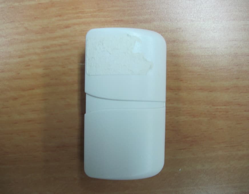
Click to zoom
Application Details
- Equipment Class
- DTS - Digital Transmission System
- Date of Grant
- Sep 21, 2011
- Application Purpose
- Original Equipment
- Date of Application
- Sep 21, 2011
- Equipment Note
- WIRELESS MAGNETIC CONTACT SENSOR
- Frequency Range
- 2405.00000000 - 2475.00000000
- Company
- Visonic Ltd.
- Country
- Israel
Documents & Files
Document Text
Text extracted from the exhibit documents filed with the FCC. Open a document above to read the original.
Users Manual
D-303359 MCT-320 SMA Installation Instructions 1 MCT-320 SMA Wireless Contact Sensor Installation Instructions 1. INTRODUCTION The MCT-320 is a fully supervised, wireless magnetic contact sensor, for use with iControl control panels. The sensor includes a built-in reed switch (that opens upon removal of a magnet placed near it). The MCT-320 tamper switch is activated when the cover is removed or when the detector is removed from the wall. A periodic supervision message is transmitted automatically. The target receiver is thus informed, at regular intervals, of the unit’s active participation in the system. Operating power is obtained from an on-board 3 V Lithium battery. When the battery voltage is low, a “low battery” message is sent to the receiver. MCT-320 SMA 2. SPECIFICATIONS WIRELESS Frequency: Frequency: 2.4 GHz as per IEEE 802.15.4 Tamper Alert: Reported when a tamper event occurs and in any subsequent message, until the tamper switch is restored. Supervision Message: Signaling at 24-minute intervals. ELECTRICAL Internal Battery: 3V Lithium battery, type CR2. Use Panasonic, GP or Sanyo only. Battery Life Expectancy: 3-5 years (for typical use). Battery Power Test: Performed immediately upon battery insertion and periodically every several hours. Battery Supervision: Automatic transmission of battery condition data as part of any status report. ENVIRONMENTAL Operating Temperature: -10C to 55C (14F to 131F). Dimensions: 51 x 30 x 21 mm (2 x 1-3/16 x 13/16 in.) Weight (including battery): 36g (1.27 oz) COMPLIANCE WITH STANDARDS Designed to comply with UL 639, ULC-S306, Title 47 CFR Part 15, IC RSS-210 This device complies with Part 15 of the FCC Rules and RSS-210 of Industry and Science Canada. Operation is subject to the following two conditions: (1) This device may not cause harmful interference, and (2) this device must accept any interference received, including interference that may cause undesired operation. Fixed frame Moving part Transmitter & magnet location marks Fig. 1 – MCT-320 SMA 3. PAIRING/DEFAULTING THE SENSOR To pair the sensor to the control panel, you must set it to pairing mode. 1. Press and hold down the sensor’s tamper switch. 2. Insert the battery into the sensor. 3. Release the tamper switch and press it again within 4 seconds. 4. Complete the pairing procedure on the control panel (see the pairing instructions in the control panel’s installation guide). 2 D-303359 MCT-320 SMA Installation Instructions 4. MOUNTING NOTE: It is highly recommended to attach the transmitter to the top of the door/window on the fixed frame and the magnet to the movable part (door or window). Make sure that the magnet is located not more than 6 mm (0.25 in.) from the transmitter’s marked side. The transmitter should be mounted on the fixed surface and the magnet on the moving surface (see Figure 1). Magnet Mounting 2 A. Fasten the spacer to mounting surface with 2 serews. B. Locate the magnet on the spacer at the correct direction and push it upwards . 1 Remove spacer Magnet 3 mm spacer 3 mm s p a c e r Fig. 2 – Magnet Mounting Magnet Mounting with Optional Spacer(s) Optional spacer(s), 3 mm width, 7mm with, or both, can be used for the magnet mounting. 1 Join the 2 spacers 3 & 7mm spacers mounting 7m m s p a c er 3m m s p ac er 2 Fasten Magnet with 3mm spacer Magnet with 7mm spacer Magnet with 3 & 7mm spacers Fig. 3 – Magnet Spacers Sensor Mounting 3 2 Fasten the bracket with 3 screws Locate and push the transmitter on the bracket 1 Push screwdriver #2 on the “stair” and turn the screwdriver clockwise to separate the transmitter from its bracket Fig. 4 – Transmitter Mounting D-303359 MCT-320 SMA Installation Instructions 3 5. TESTING THE SENSOR Close the door or window, thus restoring it to the undisturbed state. 6. TROUBLESHOOTING If you encounter one of the following problems with the MCT-320 SMA, perform the suggested remedy: Problem Remedy Attempt to pair the sensor is unsuccessful. Make sure that the sensor has been defaulted and is set to pairing mode (see section 3). The sensor and the panel do not communicate. Perform the signal strength testing procedure described in the control panel installation manual. Make sure that the signal is sufficient. If necessary, replace the sensor’s battery. ProblemRemedy The sensor sends a Low Battery indication. To ensure continuous proper operation, replace the battery within two weeks of the first Low Battery indication. Panel does not arm because of an unrecognized sensor malfunction Consult with your installer or system provider before you disable a zone. Disable the detector zone (see the control panel user manual). Note that disabling a sensor zone lowers the overall security level of your system. 7. PRODUCT LIMITATIONS Visonic Ltd. wireless systems are very reliable and are tested to high standards. However, due to low transmitting power and limited range (required by FCC and other regulatory authorities), there are some limitations to be considered: A. Receivers may be blocked by radio signals occurring on or near their operating frequencies, regardless of the digital code used. B. A receiver responds only to one transmitted signal at a time. C. Wireless devices should be tested regularly to determine whether there are sources of interference and to protect against faults. The user is cautioned that changes or modifications to the unit, not expressly approved by Visonic Ltd., could void the user’s FCC or other authority to operate the equipment. W.E.E.E. Product Recycling Declaration For information regarding the recycling of this product you must contact the company from which you orignially purchased it. If you are discarding this product and not returning it for repair then you must ensure that it is returned as identified by your supplier. This product is not to be thrown away with everyday waste. Directive 2002/96/EC Waste Electrical and Electronic Equipment. VISONIC LTD. (ISRAEL): P.O.B 22020 TEL-AVIV 61220 ISRAEL. PHONE:…
Text truncated - open the document above for the full version.
Cover Letter(s)
04 August 2011 To: Timco Engineering Inc. To Whom It May Concern We hereby authorize Shaike Raz of ITL to act on the behalf of Visonic Ltd, regarding the FCC ID Certification process for the fol lowing application FCC ID: WP3MCT320SMA Thank you, Arick Elshtein
Cover Letter(s)
Date: 04 August 2011 Federal Communications Commission Authorization and Evaluation Division Subject: Confidentiality Request regarding application for certification of FCC ID: WP3MCT320SMA Dear Sirs Pursuant to Sections 0.457 and 0.459 of the Commission’s Rules, we hereby request confidential treatment of information accompanying this application as outlined below: CONF APPENDIX MCT-320 SMA Schem.pdf CONF APPENDIX MCT-320 SMA PartsLst.pdf CONF APPENDIX MCT-320 SMA BlkDia.pdf The above materials contain trade secrets and proprietary information not customarily released to the public. The public disclosure of these materials may be harmful to the applicant and provide unjustified benefits to its competitors. The applicant understands that pursuant to Section 0.457 of the Rules, disclosure of this application and all accompanying documentation will not be made before the date of the Grant for this application. Sincerely, Arick Elshtein
Cover Letter(s)
04 August 2011 Letter of individual Authoriz ation to sign Form 731 To: Timco Engineering Inc. To Whom It May Concern We hereby authorize Shaike Raz of ITL as an authorized individual to si gn for form 731 on behalf of Visonic Ltd for the FCC ID: WP3MCT320SMA application. Thank you, Arick Elshtein
Cover Letter(s)
8 September 2011 Declaration To whom it may concern This is to confirm that none of the following products which are with ZIGBEE type RF transceiver MCT 302 SMA/MCT320 SMA/Next K9-85 SMA/Next Plus K9-85 SMA/MCT 560 SMA/MCT 550 SMA/MCT 427 SMA/MCT 442 SMA/ MCT 441 SMA, use Blue tooth communication protocol. They all use Zigbee communication protocol Arick Elshtein International Standards Manager Phone: +972 3 6456714 Fax: +972 3 6456788 Mobile: +972 54 6775714
External Photos
320 SMA‐MCT External Photos ‐Front ‐Back
ID Label/Location Info
04 August 2011 attn: Reviewing Engineer Federal Communications Commission 7435 Oakland Mills Road Columbia, MD 21046 To Whom It May Concern: 1.3 The, Wireless Magnetic Contact Sensor FCC ID: WP3MCT320SMA and label is so small that it cannot include the statement specified in FCC Part 15 Sub-part A, Section 15.19 (a) (3) “This device complies with Part 15 of the FCC Rules. Operation is subject to the following two conditions: (1) This device may not cause harmful interference and (2) This device must accept any interference received, including interference that may cause undesired operation." Due to this reason, we are using the provisions of Part 15 Sub-part A, Section 15.19 (a) (5) and this statement appears in a prominent location in the user manual. Please contact me if there is any information you may need. Thank you, Arick Elshtein
ID Label/Location Info
320 SMA ‐FCC ID Label Location MCT Label Location
ID Label/Location Info
ECM Title: VISONIC LABEL DRAWING VISONIC LTD. 14531 Product Name: LABEL MCT-320 SMA FCC Date Name Document No: 4010169 20.07.11 YANA K. Created Document Rev: 00 Updated Sheet 1 of 1 20.07.11 MICHA F. Approved MATERIAL: print on PVC S-0001-B SIZE: 25.4*12.7 mm NOTES: Description – Variable WW – Week of the year (2 digits) YY – Year (2 digits) XXXXXX – Numerator (increments by 1 until 80000 then became equal to 00001) NNNNNNNNNNNNNNNN – Variable Product MAC ID (Hexadecimal) Barcode- Code 128
Internal Photos
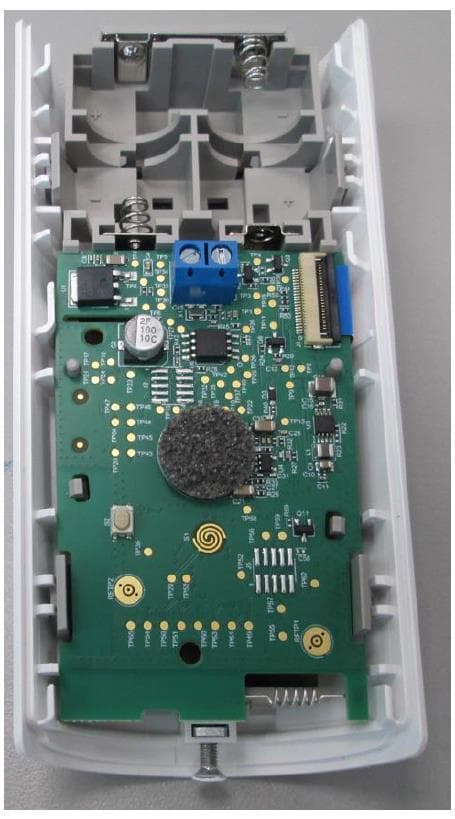
320 SMA‐Internal Photos MCT
Operational Description
MCT-320 SMA 1. INTRODUCTION The MCT-320 is a fully supervised, wireless magnetic contact sensor, for use with iControl control panels. The sensor includes a built-in reed switch (that opens upon removal of a magnet placed near it). The MCT-320 tamper switch is activated when the cover is removed or when the detector is removed from the wall. A periodic supervision message is transmitted automatically. The target receiver is thus informed, at regular intervals, of the unit’s active participation in the system. Operating power is obtained from an on-board 3 V Lithium battery. When the battery voltage is low, a “low battery” message is sent to the receiver. MCT-320 SMA 2. SPECIFICATIONS
Test Report
Test Report E107110.02 Visonic Ltd. Page 1 of 64 FCC ACC M Ver 1.1 05Mayl 2000 DATE: 19 September 2011 I.T.L. (PRODUCT TESTING) LTD. FCC Radio Test Report for Visonic Ltd. Equipment under test: Wireless Magnetic Contact Sensor MCT-320 SMA Written by: _____________________________ A. Moses, Documentation Approved by: _____________________________ A. Moses, Test Engineer Approved by: _____________________________ I. Raz, EMC Laboratory Manager This report must not be reproduced, except in full, without the written permission of I.T.L. (Product Testing) Ltd. This report relates only to items tested. Test Report E107110.02 Visonic Ltd. Page 2 of 64 FCC ACC M Ver 1.1 05Mayl 2000 Measurement/Technical Report for Visonic Ltd. Wireless Magnetic Contact Sensor MCT-320 SMA FCC ID:WP3MCT320SMA IC ID:1467C-MCT320SMA This report concerns: Original Grant: X Class I Change: Class II Change: Equipment type: Limits used: 47CFR15 Section 15.247 Measurement procedure used is ANSI C63.4-2003. Application for Certification Applicant for this device: prepared by: (different from "prepared by") Ishaihou Raz Arik Elshtein ITL (Product Testing) Ltd. Visonic Ltd. Kfar Bin Nun 24 Habarzel St. D.N. Shimshon 99780 Tel-Aviv 69710 Israel Israel e-mail [email protected] Tel: +972-3 -645-6789 Fax: +972-3- 645-6788 e-mail: [email protected] Test Report E107110.02 Visonic Ltd. Page 3 of 64 FCC ACC M Ver 1.1 05Mayl 2000 TABLE OF CONTENTS 1. GENERAL INFORMATION ------------------------------------------------------------------------------- 5 1.1 Administrative Information ................................................................................. 5 1.2 List of Accreditations ......................................................................................... 6 1.3 Product Description ........................................................................................... 7 1.4 Test Methodology .............................................................................................. 7 1.5 Test Facility ....................................................................................................... 7 1.6 Measurement Uncertainty ................................................................................. 7 2. SYSTEM TEST CONFIGURATION --------------------------------------------------------------------- 8 2.1 Justification ........................................................................................................ 8 2.2 Special Accessories .......................................................................................... 8 2.3 Equipment Modifications ................................................................................... 8 2.4 Configuration of Tested System ........................................................................ 8 3. RADIATED MEASUREMENT TEST SET-UP PHOTO -------------------------------------------- 9 4. 6DB MINIMUM BANDWIDTH --------------------------------------------------------------------------- 10 4.1 Test Specification ............................................................................................ 10 4.2 Test procedure ................................................................................................ 10 4.3 Test Results..................................................................................................... 12 4.4 Test Equipment Used. ..................................................................................... 13 5. 26DB BANDWIDTH ---------------------------------------------------------------------------------------- 14 5.1 Test Specification ............................................................................................ 14 5.2 Test procedure ................................................................................................ 14 5.3 Test Results..................................................................................................... 16 5.4 Test Equipment Used. ..................................................................................... 17 6. RADIATED POWER OUTPUT -------------------------------------------------------------------------- 18 6.1 Test Specification ............................................................................................ 18 6.2 Test procedure ................................................................................................ 18 6.3 Results Calculation .......................................................................................... 25 6.4 Test Equipment Used. ..................................................................................... 26 7. BAND EDGE ------------------------------------------------------------------------------------------------- 27 7.1 Test procedure ................................................................................................ 27 7.2 Results table .................................................................................................... 31 7.3 Test Equipment Used. ..................................................................................... 32 8. RADIATED EMISSION, 9 KHZ – 30 MHZ ------------------------------------------------------------ 33 8.1 Test Specification ............................................................................................ 33 8.2 Test Procedure ................................................................................................ 33 8.3 Measured Data ................................................................................................ 33 8.4 Test Instrumentation Used, Radiated Measurements ..................................... 34 8.5 Field Strength Calculation ............................................................................... 34 9. SPURIOUS RADIATED EMISSION 30 – 25000 MHZ --------------------------------------------- 35 9.1 Test Specification ............................................................................................ 35 9.2 Test Procedure .......…
Text truncated - open the document above for the full version.
Test Setup Photos
320 SMA‐Test setup of MCT
Contact Information
Applicant
Zuri Rubin(Certification Manager)
Test Firm
Israel Testing LaboratoriesIIan Cohen
Technical Specifications
| # | Rule Parts | Frequency Range | Power Output |
|---|---|---|---|
| 1 | 15C | 2.40 GHz - 2.48 GHz | 15.00 mW |
Other Applications from Visonic Ltd.
WP3NEXTCAMPGP
Dec 21, 2023Wireless Motion detector with integrated camera
Equipment Class
DSS - Part 15 Spread Spectrum Transmitter
WP3RP600PGP
May 16, 2023Wireless Repeater for PowerG Communications
Equipment Class
DSS - Part 15 Spread Spectrum Transmitter
WP3PGMODIQREM
Jun 02, 2021Power-G Modem iQ Remote
Equipment Class
DSS - Part 15 Spread Spectrum Transmitter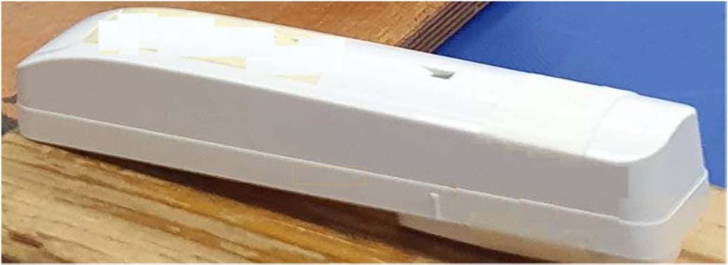
WP3SD304EPG2
Jan 03, 2021PowerG Wireless Shock Detector
Equipment Class
DSS - Part 15 Spread Spectrum Transmitter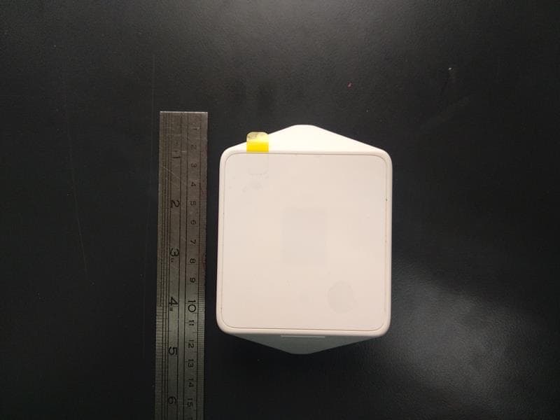
WP3MP843
Jun 30, 2020PIR detector ZigBee
Equipment Class
DTS - Digital Transmission System