WP3MCT350SMA5Zigbee Door / Window Contact
Visonic Ltd.
Click to zoom
Application Details
- Equipment Class
- DTS - Digital Transmission System
- Date of Grant
- Dec 14, 2015
- Application Purpose
- Original Equipment
- Date of Application
- Dec 14, 2015
- Equipment Note
- Zigbee Door / Window Contact
- Frequency Range
- 2405.00000000 - 2480.00000000
- Company
- Visonic Ltd.
- Country
- Israel
Documents & Files
Document Text
Text extracted from the exhibit documents filed with the FCC. Open a document above to read the original.
Users Manual
MCT-350 Installation Instructions 1 Comcast MCT-350 Door / Window Sensor Installation Instructions 1. INTRODUCTION The MCT-350 is a fully supervised, wireless magnetic door / window sensor, for use with ZigBee enabled home security panels. The sensor includes a built-in reed switch (that opens upon removal of a magnet placed near it). The MCT-350 tamper switch is activated when the cover is removed. A periodic supervision message is transmitted automatically. The target receiver is thus informed, at regular intervals, of the unit’s active participation in the system. Operating power is obtained from an on-board 3 V Lithium battery. When the battery voltage is low, a “low battery” message will be sent to the receiver 60 days before expiration of battery life (for operation in room temperature). Figure 1 – External View 2. SPECIFICATIONS WIRELESS Supported Network: ZigBee H.A 1.2 Frequency: 2.4 GHz as per IEEE 802.15.4 Tamper Alert: Reported when a tamper event occurs and in any subsequent message, until the tamper switch is restored. ELECTRICAL Internal Battery: 3V Lithium battery, type CR2450. Use Varta only. Nominal Battery Capacity: 620 mAh Battery Life Expectancy: 5 years (for typical use). Note: Inability to connect with wireless network, or wireless link quality no higher than 20% may significantly reduce the expected battery life. Battery Power Test: Performed immediately upon battery insertion and periodically every several hours. Battery Supervision: Automatic transmission of battery condition data as part of any status report. ENVIRONMENTAL Operating Temperature: 0°C to 50°C (32°F to 122°F) Humidity: 93% RH, non-condensing Dimensions: 66 x 25 x 10 mm (2-9/16 x 1 x 6/16 in.) Weight (including battery): 15 g (0.5 oz) 3. ACTIVATING AND PAIRING THE SENSOR To pair the sensor to the security panel, you must set it to pairing mode. 1. First set the panel to pairing mode and then the sensor. 2. To activate, pull the activation strip (from either side) that protrudes from the back of the sensor. 3. The LED blinks 3 times every 5 seconds (repeated for up to 20 times) to indicate that the sensor is searching for a security panel. Note: If sensor pairing is not successful during the searching process - by tripping the door / window sensor or by pressing the tamper switch - the searching process will restart. 4. Complete the pairing procedure on the security panel (see the pairing instructions in the security panel’s installation guide). Note: Pairing should be performed before installation. Figure 2 – Activation Strip 4. INSTALLATION AND SENSOR TESTING CAUTION: This equipment shall be installed by Service Personnel in non-hazardous indoor locations only. 4.1 Mounting NOTE: It is highly recommended to attach the door / window sensor to the top of the door/window on the fixed frame and the magnet to the movable part (door or window). Make sure that the magnet is located not more than 6 mm (0.25 in.) from the sensor’s marked side. The sensor should be mounted on the fixed surface and the magnet on the moving surface (see Figure 3b). Fig. 3a – Attaching the Adhesive Tape 1. Peel away the release liners from the two strips of double-sided adhesive tape and attach to the device and magnet. Fig. 3b – Mounting on Fixed Surface 2. Align the device with the magnet according to the location marks and fasten the device and magnet to the mounting surface. The sensor should be mounted on the fixed surface and magnet on the moving surface. A. Double-sided adhesive tape B. Magnetic location marks Note: Silicone can also be used to securely mount the device and magnet. 4.2 Sensor Testing Close the door or window, thus restoring it to the undisturbed state 5. BATTERY REPLACEMENT Fig. 4a – Opening Battery Cover Fig. 4b –Replacing Battery 1. Press down on the battery cover and slide in the direction shown in Figure 4a to open. 2. Push against the clip and lift the battery from the slot below it. 3. Insert the new battery into the sensor while observing battery polarity (see Figure 4b). 4. Close the battery cover. Note: The required battery is CR2450 Lithium 3V, manufactured by VARTA. Caution! Risk of explosion if battery is replaced by an incorrect type. Dispose of used battery according to the manufacturer's instructions. 2 MCT- 35 0 Installation Instructions 6. REBOOTING THE SENSOR You can reboot the sensor, as follows: 1.Remove the battery cover. 2.Press and release the tamper switch for 1 to 2 sec. (see Figure 4b). 3.Close the battery cover. 7. DEFAULTING THE SENSOR CAUTION! T he defaulting process removes the device from the network and enables re-pairing. Open the battery cover and pull back the clip to remove the battery (see Figure 4). 1.Press and hold down the sensor’s tamper switch (see Figure 4b). 2.Insert the battery into the sensor while observing battery polarity (see Figure 4b). 3.Release the tamper switch within 4 seconds (the LED blinks 3 times every 5 seconds). 4.To re-pair the sensor, follow the instructions in section 3. 8. TROUBLESHOOTING If you encounter one of the following problems with the MCT-350 , perform the suggested remedy: Problem Remedy Attempt to pair the sensor is unsuccessful. Make sure that the sensor has been defaulted and is set to pairing mode (see section 4). Make sure the security panel supports the MCT-350. The sensor and the panel do not communicate. Perform the signal strength testing procedure described in the security panel installation manual. Make sure that the signal is sufficient. If necessary, replace the sensor’s battery. Problem Remedy The sensor sends a Low Battery indication. To ensure continuous proper operation, replace the battery within two weeks of the first Low Battery indication. Panel does not arm because of an unrecognized sensor malfunction Consult with your installer or system provider before you disable a zone. Disable the detector zone (see the security panel user manual). Note that disabling a sensor zone lowers the overall security level of …
Text truncated - open the document above for the full version.
Cover Letter(s)
Visonic Ltd. 24 Habarzel Street P.O.Box 22020 Tel-Aviv 69710, Israel Tele: +972 3 645 6789 Fax: +972 3 645 6788 www.visonic.com December 1st, 2015 To Whom It May Concern: The Visonic Zigbee Door/Window contacts MCT-350 SMA and XHS2-TY are built using the same enclosure, hardware (RF circuitry) and have identical functionality. The only difference is the marketing name. The testing of model MCT-350 SMA is representative for all models in this family. Respectfully yours, Arik Elshtein Approvals Manager
Cover Letter(s)
Visonic Ltd. 24 Habarzel Street P.O.Box 22020 Tel-Aviv 69710, Israel Tele: +972 3 645 6789 Fax: +972 3 645 6788 www.visonic.com December 1, 2015 Equipment Autorisation Division Federal Communications Commission 7435 Oakland Mills Road Columbia, MD 21046 FCC ID: WP3MCT350SMA5 Product Name: Zigbee Door/Window Contact Models: MCT-350 SMA, XHS2-TY Request for Confidentiality Pursuant to Sections 0.457 and 0.459 of the commission’s rules, we hereby request that the following documents be held confidential: • Schematics • Block diagram • Operational Description • Parts List These materials contain trade secrets and proprietary information and are not customarily released to the public. The public disclosure of this information might be harmful to the company and provide unjustified benefits to our competitors. Dated this 1st Day of December 20 15 By: Arik Elshtein Signature Printed Title: Approvals Manager On behalf of : Visonic Ltd. Telephone: +972 3 6456832
Cover Letter(s)
Visonic Ltd. 24 Habarzel Street P.O.Box 22020 Tel-Aviv 69710, Israel Tele: +972 3 645 6789 Fax: +972 3 645 6788 www.visonic.com December 1, 2015 Nemko Canada Inc 303 River Road Ottawa, Ontario, Canada K1V 1H2 Attn: Director of Certification Authority to Act as Agent On our behalf, I appoint Nemko Canada Inc., 303 River Road, Ottawa, Ontario, Canada K1V 1H2 to act as our agent in the preparation of this application for equipment certification. I certify that submitted documents properly describe the device or system for which equipment certification is sought. I also certify that each unit manufactured, imported or marketed, as defined in the Federal Communications Commission’s regulations will have affixed to it a label identical to that submitted for approval with this application. For instances where our authorized agent signs the application for certification on our behalf, I acknowledge that all responsibility for complying with the terms and conditions for certification, as specified by Nemko Canada Inc, still resides with Visonic Ltd., 24 Habarzel Str., Tel Aviv, Israel 61920. Dated this 1st Day of December 20 15 Agency agreement expiration date: November 30th, 2016 By: Arik Elshtein Signature Printed Title: Approvals Manager On behalf of : Visonic Ltd. Telephone: +972 3 6456832
ID Label/Location Info
18009405R001 XHS2-TY(MCT-350) Product Label Digital Security Controls 3301 Langstaff Road Concord, Ontario Canada L4K 4L2 Tele: 905 760 3000 Toll Free: 888 888 7838 Fax: 905-760-3020 Font: X nity Sans 3pt-4.5pt Alignment/Spacing: Sticker and sticker elements (icons, text, etc.) should be centred vertically and horizontally to product elements. Sticker Recess: .08mm deboss and .15mm o set from sticker edge. Sticker Text/Icon Color: PMS Cool Grey 7C. Sticker CMF: PMS Cool Grey 3C satin nish MT11005. QR Code: PMS Cool Grey 7C on White Background. QR code should contain Device Name, Serial Number and MAC address. Product name: XHS2-TY where “TY” is the assigned vendor code. Stock Label: P/N: 18009447R001- MCT-350 PRODUCT LABEL 20MM X 28MM ADHE- SIVE PMS COOL GREY 3C SATIN FINISH MT11005. YYMMDDFID: “FID” stands for “Factory ID”. This identi es the ID of the factory where the product was manufactured. “YYMMDD” is the date of production. Sticker (outlined in blue) should be in a deboss recess .06mm and . 15mm o set along edges. SN: TYWWYYAXXXXX ZID: XXXXXXXXXXXXXXXX YYMMDDFID 5000245 Battery type: CR2450/3V FCC ID: WP3MCT350SMA5 IC: 1467C-MCT350SMA 20mm 28mm Marks centred horizontally to main housing QR Code PMS Cool Grey 7C on White Background. QR Code should contain Device Name, Serial Number and MAC address. Sticker centred horizontally to main housing (rear side) 1:1 Scale QR Code Sizing Not to Scale QR Code must be 7mm x 7mm, on white background, and have .3mm white border on all sides. 7mm 7mm .3mm .3mm .3mm .3mm XHS2-TY : WP3MCT350SMA5 IC:1467C-MCT350SMA XHS2-TY SN: TYWWYYAXXXXX ZID: XXXXXXXXXXXXXXXX YYMMDDFID Battery type: CR2450/3V
Internal Photos
MCT‐350 SMA (UA695 Rev 05) PCB assembly top side view MCT‐350 SMA (UA695 Rev 05) PCB assembly rear side view
Test Report
www.nemko.com Nemko Canada Inc., a testing laboratory, is accredited by the Standards Council of Canada. The tests included in this report are within the scope of this accreditation FCC 15.247 and RSS-247.docx; Date: May 2015 ONE WORLDOURAPPROVAL Test report 295231-1TRFWL Date of issue: December 14, 2015 Applicant: Visonic Ltd. Product: Wireless Door/Window Contact Model: MCT-350 SMA and XHS2-TY FCC ID: IC Registration number: WP3MCT350SMA5 1467C-MCT350SMA Specifications: FCC 47 CFR Part 15 Subpart C, §15.247 Operation in the 902–928 MHz, 2400–2483.5 MHz, 5725–5850 MHz RSS-247, Issue 1, May 2015, Section 5 Digital Transmission Systems (DTSs), Frequency Hopping Systems (FHSs) and Licence-Exempt Local Area Network (LE-LAN) Devices Report reference ID: 295231-1TRFWL Page 2 of 24 Test location Company name Nemko Canada Inc. Address 303 River Road City Ottawa Province Ontario Postal code K1V 1H2 Country Canada Telephone +1 613 737 9680 Facsimile +1 613 737 9691 Toll free +1 800 563 6336 Website www.nemko.com Site number FCC: 176392; IC: 2040A-4 (3 m semi anechoic chamber) Tested by Kevin Rose, Wireless/EMC Specialist Reviewed by Andrey Adelberg, Senior Wireless/EMC Specialist Review date December 14, 2015 Reviewer signature Limits of responsibility Note that the results contained in this report relate only to the items tested and were obtained in the period between the date of initial receipt of samples and the date of issue of the report. This test report has been completed in accordance with the requirements of ISO/IEC 17025. All results contain in this report are within Nemko Canada’s ISO/IEC 17025 accreditation. Copyright notification Nemko Canada Inc. authorizes the applicant to reproduce this report provided it is reproduced in its entirety and for use by the company’s employees only. Any use which a third party makes of this report, or any reliance on or decisions to be made based on it, are the responsibility of such third parties. Nemko Canada Inc. accepts no responsibility for damages, if any, suffered by any third party as a result of decisions made or actions based on this report. © Nemko Canada Inc. Report reference ID: 295231-1TRFWL Page 3 of 24 Table of contents Table of contents .......................................................................................................................................................................................................... 3 Section 1. Report summary ................................................................................................................................................................................. 4 1.1 Applicant and manufacturer .................................................................................................................................................................................... 4 1.2 Test specifications .................................................................................................................................................................................................... 4 1.3 Test methods ............................................................................................................................................................................................................ 4 1.4 Statement of compliance ......................................................................................................................................................................................... 4 1.5 Exclusions ................................................................................................................................................................................................................. 4 1.6 Test report revision history ...................................................................................................................................................................................... 4 Section 2. Summary of test results ....................................................................................................................................................................... 5 2.1 FCC Part 15 Subpart C, general requirements test results ........................................................................................................................................ 5 2.2 FCC Part 15 Subpart C, intentional radiators test results.......................................................................................................................................... 5 2.3 IC RSS-GEN, Issue 4, test results ............................................................................................................................................................................... 5 2.4 IC RSS-247, Issue 1, test results ................................................................................................................................................................................ 6 Section 3. Equipment under test (EUT) details ..................................................................................................................................................... 7 3.1 Sample information .................................................................................................................................................................................................. 7 3.2 EUT information ....................................................................................................................................................................................................... 7 3.3 Technical information .............................................................................................................................................................................................. 7 3.4 Product description and theory of operation .......................................................................................…
Text truncated - open the document above for the full version.
Test Setup Photos
www.nemko.com Nemko Canada Inc., a testing laboratory, is accredited by the Standards Council of Canada. The tests included in this report are within the scope of this accreditation setup photos.docx; Date: May 2013 SCC Accredited LAB LAB Accrédité CCN TM ONE WORLDOURAPPROVAL Setup photos 295231-3RADWL Date of issue: December 1, 2015 Applicant: Visonic Ltd. Product: Wireless Door/Window Contact Model MCT-350 SMA FCC ID: IC Registration number: WP3MCT350SMA5 1467C-MCT350SMA Section 1: Setup photos Report reference ID: 295231-3RADWL Page 2 of 2 Section 1. Setup photos 1.1 Radiated Emissions
Contact Information
Applicant
Zuri Rubin(Certification Manager)
Test Firm
Nemko Canada Inc. (Ottawa)Charles Neal
Technical Specifications
| # | Rule Parts | Frequency Range | Power Output |
|---|---|---|---|
| 1 | 15C | 2.40 GHz - 2.48 GHz | 6.70 mW |
Other Applications from Visonic Ltd.
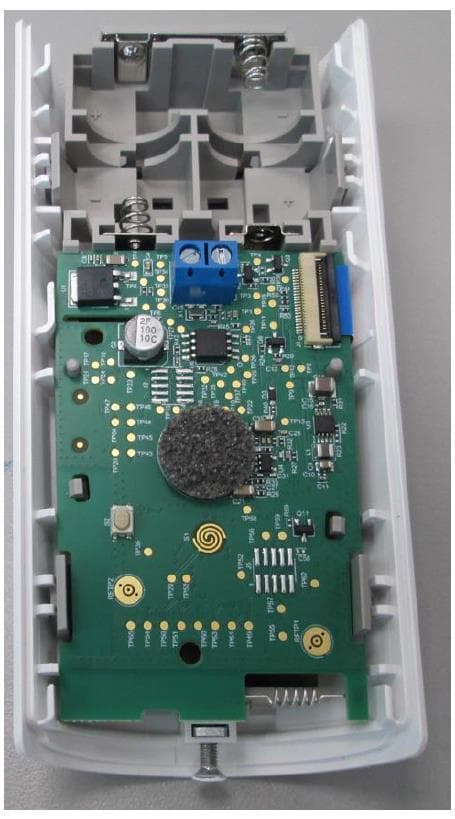
WP3NEXTCAMPGP
Dec 21, 2023Wireless Motion detector with integrated camera
Equipment Class
DSS - Part 15 Spread Spectrum Transmitter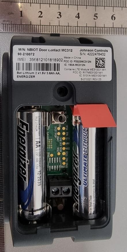
WP3RP600PGP
May 16, 2023Wireless Repeater for PowerG Communications
Equipment Class
DSS - Part 15 Spread Spectrum Transmitter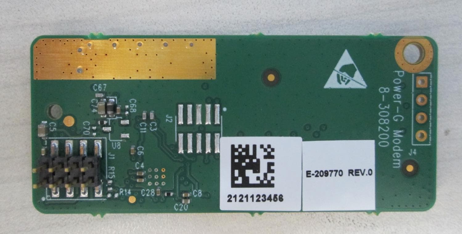
WP3PGMODIQREM
Jun 02, 2021Power-G Modem iQ Remote
Equipment Class
DSS - Part 15 Spread Spectrum Transmitter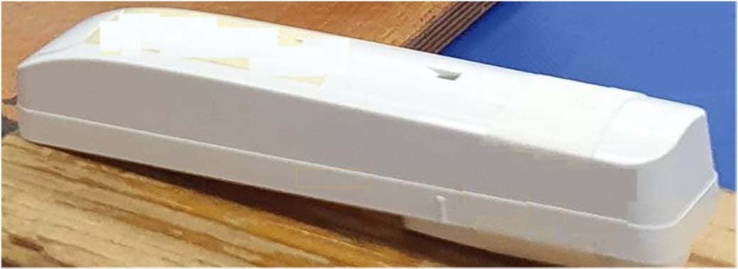
WP3SD304EPG2
Jan 03, 2021PowerG Wireless Shock Detector
Equipment Class
DSS - Part 15 Spread Spectrum Transmitter
WP3MP843
Jun 30, 2020PIR detector ZigBee
Equipment Class
DTS - Digital Transmission System