WP3MCT426-MCT427Smoke and heat detector
Visonic Ltd.
Click to zoom
Application Details
- Equipment Class
- DSC - Part 15 Security/Remote Control Transmitter
- Date of Grant
- Mar 25, 2010
- Application Purpose
- Original Equipment
- Date of Application
- Mar 25, 2010
- Equipment Note
- Smoke and heat detector
- Frequency Range
- 315.00000000 - 315.00000000
- Company
- Visonic Ltd.
- Country
- Israel
Documents & Files
Document Text
Text extracted from the exhibit documents filed with the FCC. Open a document above to read the original.
Users Manual
D-302151 1 MCT-426, MCT-427 Supervised Wireless PowerCode Smoke / Heat and Smoke Detector Installation Instructions 1. DESCRIPTION AND APPLICATIONS MCT-426 (smoke detector) and MCT-427 (heat and smoke detector) are heat and smoke automatic fire detectors with integral audible signal for open area protection, designed to sense heat or smoke (not flame) and fitted with a PowerCode type UHF transmitter. MCT-426 / MCT-427 provides early warning of developing fire by sounding an alarm with its built-in alarm horn, and by transmitting a coded alarm signal to a PowerCode receiver or to a compatible wireless alarm control panel. For UL approved installation use only PowerMax+ control panel. It must be borne in mind, though that effective prewarning of fire accidents is only possible if the detector is located, installed and maintained as described here. In alarm condition, the buzzer sound can be stopped for 12 minutes by pressing the TEST/MUTE switch. It will not restore the alarm condition, but will temporarily silence the buzzer while you correct the condition. After 12 minutes, the detector restarts the alarm buzzer sound. Note: The TEST/MUTE switch functions as TEST switch (in normal operation) or as MUTE switch (in alarm condition). The tamper switch actuator (Fig. 3) is pressed against the bracket when the unit is attached to the bracket. Removal of the unit from the bracket causes the switch contacts to open, creating a tamper event, which is reported by the transmitter to the alarm system control panel. BUZZER HOLE TEST / MUTE BUTTON & LEDS Figure 1. General View (MCT-427) 2. SPECIFICATIONS SMOKE DETECTOR Alarm Sound Level: 85 dB at 3 m (10 feet) TRANSMITTER AND CODING Operating Frequency (MHz): 315, 433.92, 868.95, 869.2125 or other frequency according to local requirements. Transmitter's ID Code: 24-bit digital word, over 16 million combinations, pulse width modulation. Overall Message Length: 36 bits Supervision: Automatic signaling at 60-minute intervals (315 MHz version), 15-minute interval (433.92, 868.95, 869.2125 MHz versions) or according to the local standards. Tamper Alerts: Tamper event (removal of the unit from its bracket) is reported once. Tamper restore is reported when the tamper switch is restored. Transmission Indicator: Yellow LED lights upon transmission (visible only when LED function is pre-defined). ALARM REPORT: Every 3 min. for the next 30 minutes. Alarm stops reporting after 30 min., or if the detector goes into "alarm restore". After 30 minutes, an alarm bit will be sent as part of the supervision message. ELECTRICAL DATA Power Source: 3 Volt CR123A / CR17450 lithium. Operation Voltage: From 2.7 V to 3 V. Current Drain: 18 μA standby, 70 mA max. in operation Smoke Density: Europe: 0.09 – 0.14 dB/m USA: 1.44%/ft to 2.74%/ft Cover Range: 50 – 100 cubic meters (1770 – 3530 cubic ft.) Battery Supervision: Automatic transmission of battery status data as part of any transmitted message. Battery Life Expectancy: 5 years for CR123A, 8 years for CR17450. Audible and Visual Low Battery Warning: Built-in horn beeps every 30 seconds simultaneously with red LED flashing (for up to 30 days when the battery voltage drops). Note: Dispose of used batteries according to the manufacturer's instructions. Audible and Visual Degraded Chamber Sensitivity Warning: Built-in horn beeps every 30 seconds in the middle of red LED flashing intervals – indicates that the detector must be replaced. Clean Warning Transmission: A clean (maintenance) signal is transmitted when the detector's chamber becomes stained, causing the detector to operate at high sensitivity. Note: This transmission applies to the PowerMax+ control panel only. PHYSICAL DATA Operating Temperature: -10°C to 50°C (14°F to 122°F). Relative Humidity: 10% to 85% Dimensions: MCT-426 120 mm (4.7") x 58 mm (2.3") MCT-427 120 mm (4.7") x 63 mm (2.5") Weight (including battery): 165 g (5.8 oz) Compliance with Standard: MCT-426/427 Europe: (868.95, 433.92 and 869.2125 MHz): EN54-7 (except for § 4.2), EN 14604. EN 54-5 (except for § 4.4), EN 60950, EN 300220, EN 301489, EN 50130-4. USA: 315MHz (FCC) CFR47 Part 15 Canada: (315 MHz): RSS210 Designed to comply with: MCT-426/427 USA (315MHz): UL 268 3. INSTALLATION 3.1 Disassembly Separate the unit from its mounting bracket as shown in Figure 2. BRACKETDETECTOR 1 Hold the bracket with one hand 2 Rotate the detector anticlockwise and pull it from the bracket Figure 2. Separating the Detector from Its Bracket 2 D-302151 3.2 Audible and Visual Indications The dual color LED and buzzer are used to signal various alarm and trouble messages as shown in Table 1 below: Table 1. Visual and Audible Indications Visual Indication (LEDs) Condition Red Yellow Audio Indication Smoke alarm Flash every 500ms - 3 long beeps every 4 sec. Heat alarm(***) Flash every 500ms - Long beep every 2 sec. Tamper alarm(*) - - Long beep every 2 sec. Standby Flash every 30 sec. - - Low battery Flash every 30 sec. - Short beep every 30 sec. Smoke sensor trouble Flash every 60 sec. 3 Flashes every 60 sec. Short beep every 60 sec. Low sensitivity alarm Flash every 30 sec.(**) - Short beep every 30 sec. Heat sensor trouble(***) Flash every 60 sec. 5 Flashes every 60 sec. Short beep every 60 sec. Need to clean 2 flashes every 30 sec. - 2 short beeps every 30 sec. Test See par. 3.7 * The tamper alarm will mute for 3 minutes at first power on, and will revert to normal mode when the tamper switch condition is changed. ** Delay of 15 sec. between buzzer beep and LED operation *** MCT-427 only 3.3 Battery Connection and Initial Test Attention: The detector battery cover is fitted with a red button that prevents the detector from locking onto bracket if there is no battery inside. The smoke detector is supplied with a 3V CR123A / CR17450 battery. Battery connection for both types of batteries is illustrated in Figure 3a and 3b below. Battery cover Open battery cover and connect the battery to its terminals (without insulator…
Text truncated - open the document above for the full version.
Cover Letter(s)
Declaration of Authorization We Name: Visonic Ltd. Address: Habarzel street 24, City: Tel Aviv 69710, Country: Israel ............................................................................ Declare that: Agent Company name: Hermon Laboratories Ltd. Address: Harakevet Industrial Zone City: Binyamina 30500 Country Israel is authorized to apply for Certification of the following product(s): Product description: ...Wireless Smoke and Heat Detectors ....... Type designation: ... MCT-426, MCT-427 .................. . Trademark: ... Visonic ........................................... on our behalf. Date: March 08, 2010 Name: Arik Elshtein .......................... (2) Function: International Standards Department Manager Signature:
Cover Letter(s)
To: Telefication B.V. Attn: Dept. FCC TCB Edisonstraat 12A 6902 PK ZEVENAAR The Netherlands Subject: Request for confidentiality FCC ID:WP3MCT426-MCT427 Reference number: 20149 Dear FCC TCB, Persuant to 47 CFR Section 0.459(a) & (b), Visonic Ltd. hereby requests non-disclosure and confidential treatment of the following materials submitted in support of FCC certification application for FCC ID:WP3MCT426-MCT427: Block Diagrams Operational Description Schematic Diagrams Above materials contain secrets, proprietary and technical information, which would customarily be quarded from competitors under 47 CFR, section 0.457(d)(2). Disclosure or publication or any portion of this company confidential material to other parties could cause substantial competitive harm and provide unjustified benefits for competitors. Visonic Ltd. understands that pursuant to 47 CFR section 0.457(d)(1)(ii) disclosure of the applicant and all accompanying documentation will not be made before the date of the grant. 8 March 2010 Tel Aviv Arik Elshtein
External Photos
Visonic Ltd. FCC ID: WP3MCT426-MCT427 IC:1467C-MCT426427 Page 1 of 4 EXTERNAL PHOTOGRAPHS This document contains 3 photographs Visonic Ltd. FCC ID: WP3MCT426-MCT427 IC:1467C-MCT426427 Page 2 of 4 Photograph No.1 MCT-426 detector front view Visonic Ltd. FCC ID: WP3MCT426-MCT427 IC:1467C-MCT426427 Page 3 of 4 Photograph No.2 MCT-427 detector front view Visonic Ltd. FCC ID: WP3MCT426-MCT427 IC:1467C-MCT426427 Page 4 of 4 Photograph No.3 MCT-426/ MCT-427 detector rear side view
ID Label/Location Info
Visonic Ltd. FCC ID:WP3MCT426-MCT427 IC:1467C-MCT426427 Label_location_20149.doc Page 1 of 2 Label location on the MCT-426/MCT-427 detector Label with FCC ID:WP3MCT426-MCT427 and IC:1467C- MCT426427 will be located at the rear side panel. The statement according to FCC part 15 §15.19(a)(3) is placed in Installation Instructions, page 6 (Application exhibit Users_manual_20149). Visonic Ltd. FCC ID:WP3MCT426-MCT427 IC:1467C-MCT426427 Label_location_20149.doc Page 2 of 2 Label of MCT-426 detector Label of MCT-427 detector
Internal Photos
Visonic Ltd. FCC ID: WP3MCT426-MCT427 IC:1467C-MCT426427 Page 1 of 8 INTERNAL PHOTOGRAPHS This document contains 7 photographs Visonic Ltd. FCC ID: WP3MCT426-MCT427 IC:1467C-MCT426427 Page 2 of 8 Photograph No.1 MCT-426 detector internal view Visonic Ltd. FCC ID: WP3MCT426-MCT427 IC:1467C-MCT426427 Page 3 of 8 Photograph No.2 MCT-427 detector internal view Visonic Ltd. FCC ID: WP3MCT426-MCT427 IC:1467C-MCT426427 Page 4 of 8 Photograph No.3 MCT-426 detector internal view with shield removed Visonic Ltd. FCC ID: WP3MCT426-MCT427 IC:1467C-MCT426427 Page 5 of 8 Photograph No.4 MCT-427 detector internal view with shield removed Visonic Ltd. FCC ID: WP3MCT426-MCT427 IC:1467C-MCT426427 Page 6 of 8 Photograph No.5 Detector main PCB second side view Visonic Ltd. FCC ID: WP3MCT426-MCT427 IC:1467C-MCT426427 Page 7 of 8 Photograph No.6 Detector RF module front view Visonic Ltd. FCC ID: WP3MCT426-MCT427 IC:1467C-MCT426427 Page 8 of 8 Photograph No.7 RF module PCB second side view
Test Report
Hermon Laboratories Ltd. Harakevet Industrial Zone, Binyamina 30500, Israel Tel. +972-4-6288001 Fax. +972-4-6288277 E-mail: [email protected] Page 1 of 55 Report ID: VISRAD_FCC.20149.doc Date of Issue: 2/21/2010 Electrical 839.01 TEST REPORT ACCORDING TO: FCC CFR 47 PART 15 Subpart C, section 15.231 and subpart B; RSS-210, Issue 7, Annex 1; ICES-003 Issue 4:2004 FOR: Visonic Ltd. PowerCode Smoke Detector, model MCT-426 PowerCode Heat and Smoke Detector, model MCT-427 This report is in conformity with ISO/ IEC 17025. The "A2LA Accredited" symbol endorsement applies only to the tests and calibrations that are listed in the scope of Hermon Laboratories accreditation. The test results relate only to the items tested. This test report shall not be reproduced in any form except in full with the written approval of Hermon Laboratories Ltd. Report ID: VISRAD_FCC.20149.doc Date of Issue: 2/21/2010 Page 2 of 55 Table of contents 1 Applicant information..................................................................................................................................................... 3 2 Equipment under test attributes .................................................................................................................................... 3 3 Manufacturer information .............................................................................................................................................. 3 4 Test details.................................................................................................................................................................... 3 5 Tests summary.............................................................................................................................................................. 4 6 EUT description............................................................................................................................................................. 5 6.1 General information....................................................................................................................................................... 5 6.2 Test configuration.......................................................................................................................................................... 5 6.3 Changes made in EUT .................................................................................................................................................. 5 6.4 Transmitter characteristics ............................................................................................................................................ 6 7 Transmitter tests according to 47CFR part 15 subpart C requirements ........................................................................ 7 7.1 Periodic operation requirements ................................................................................................................................... 7 7.2 Field strength of emissions.......................................................................................................................................... 14 7.3 Occupied bandwidth test ............................................................................................................................................. 33 7.4 Antenna requirements ................................................................................................................................................. 35 7.5 Radiated emission measurements .............................................................................................................................. 36 8 APPENDIX A Test equipment and ancillaries used for tests....................................................................................... 42 9 APPENDIX B Measurement uncertainties................................................................................................................... 43 10 APPENDIX C Test laboratory description ................................................................................................................... 44 11 APPENDIX D Specification references ....................................................................................................................... 44 12 APPENDIX E Test equipment correction factors......................................................................................................... 45 13 APPENDIX F Abbreviations and acronyms................................................................................................................. 55 Report ID: VISRAD_FCC.20149.doc Date of Issue: 2/21/2010 Page 3 of 55 1 Applicant information Client name: Visonic Ltd. Address: Habarzel street 24, Tel Aviv 69710, Israel Telephone: +972 3645 6789 Fax: +972 3645 6788 E-mail: [email protected] Contact name: Mr. Arik Elshtein 2 Equipment under test attributes Products names: PowerCode Smoke Detector, model MCT-426 PowerCode Heat and Smoke Detector, model MCT-427 Product type: Transmitter Operating frequency: 315 MHz Hardware version: NP1360-R Ver. 1.0, PCB layout from July 06, 2009 Software release: JS-701342_Ver_2.S19 (Visonic P/N JS-701342) RF module hardware: E-2348-1 RFT-302A 3V Receipt date 1/7/2010 3 Manufacturer information Manufacturer name: Visonic Ltd. Address: Habarzel street 24, Tel Aviv 69710, Israel Telephone: +972 3645 6789 Fax: +972 3645 6788 E-Mail: [email protected] Contact name: Mr. Arik Elshtein 4 Test details Project ID: 20149 Location: Hermon Laboratories Ltd. Harakevet Industrial Zone, Binyamina 30500, Israel Test started: 1/7/2010 Test completed: 2/21/2010 Test specification(s): FCC Part 15, subpart C, §15.231; subpart B, §15.109 RSS-210 Issue 7:2007, Annex 1; ICES-003 issue 4:2004 Report ID: VISRAD_FCC.20149.doc Date of Issue: 2/21/2010 Page 4 of 55 5 Tests summary Test Status Transmitter characteristics FCC Part 15, Section 231(a) / RSS-210, Section A1.1.1, Periodi…
Text truncated - open the document above for the full version.
Test Setup Photos
Visonic Ltd. FCC ID: WP3MCT426-MCT427 IC:1467C-MCT426427 Page 1 of 8 SETUP PHOTOGRAPHS This document contains 7 photographs Visonic Ltd. FCC ID: WP3MCT426-MCT427 IC:1467C-MCT426427 Page 2 of 8 Photograph No.1 Setup for spurious emission field strength measurements in the anechoic chamber below 30 MHz Visonic Ltd. FCC ID: WP3MCT426-MCT427 IC:1467C-MCT426427 Page 3 of 8 Photograph No.2 Setup for carrier and spurious emission field strength measurements in the anechoic chamber in 30 – 1000 MHz range Visonic Ltd. FCC ID: WP3MCT426-MCT427 IC:1467C-MCT426427 Page 4 of 8 Photograph No.3 Setup for carrier and spurious emission field strength measurements in the anechoic chamber above 1000 MHz range Visonic Ltd. FCC ID: WP3MCT426-MCT427 IC:1467C-MCT426427 Page 5 of 8 Photograph No.4 Setup for spurious emission field strength measurements at the OATS above 1000 MHz range Visonic Ltd. FCC ID: WP3MCT426-MCT427 IC:1467C-MCT426427 Page 6 of 8 Photograph No.5 Setup for occupied bandwidth measurements Visonic Ltd. FCC ID: WP3MCT426-MCT427 IC:1467C-MCT426427 Page 7 of 8 Photograph No.6 Setup for radiated emission measurements in the anechoic chamber in 30 – 1000 MHz range Visonic Ltd. FCC ID: WP3MCT426-MCT427 IC:1467C-MCT426427 Page 8 of 8 Photograph No.7 Setup for radiated emission measurements in the anechoic chamber above 1000 MHz range
Contact Information
Applicant
Zuri Rubin(Certification Manager)
Technical Contact
Hermon Laboratories Ltd.Michael Nikishin
[email protected]+972 4626 8440
Harakevet Industrial zone, · Binyamina · Israel
Test Firm
Hermon Laboratories Ltd.Alexander Usoskin
Technical Specifications
| # | Rule Parts | Frequency Range | Power Output |
|---|---|---|---|
| 1 | 15.231 | 315 MHz - 315 MHz | - |
Other Applications from Visonic Ltd.
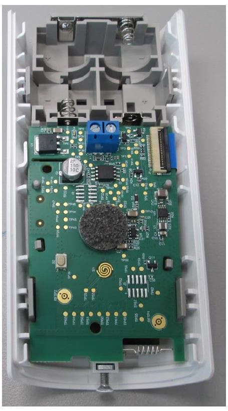
WP3NEXTCAMPGP
Dec 21, 2023Wireless Motion detector with integrated camera
Equipment Class
DSS - Part 15 Spread Spectrum Transmitter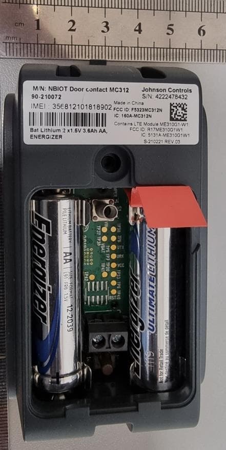
WP3RP600PGP
May 16, 2023Wireless Repeater for PowerG Communications
Equipment Class
DSS - Part 15 Spread Spectrum Transmitter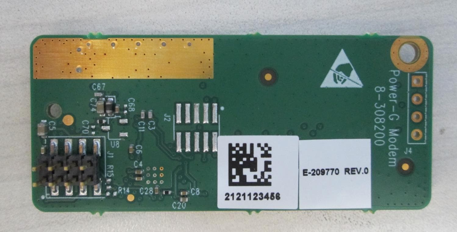
WP3PGMODIQREM
Jun 02, 2021Power-G Modem iQ Remote
Equipment Class
DSS - Part 15 Spread Spectrum Transmitter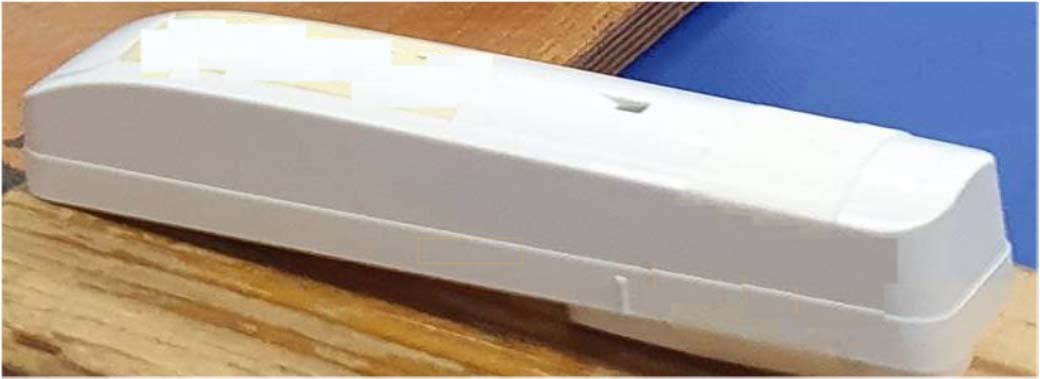
WP3SD304EPG2
Jan 03, 2021PowerG Wireless Shock Detector
Equipment Class
DSS - Part 15 Spread Spectrum Transmitter
WP3MP843
Jun 30, 2020PIR detector ZigBee
Equipment Class
DTS - Digital Transmission System