WP3MCX610WIRELESS REPEATER FOR POWER CODE COMMUNICATIONS
Visonic Ltd.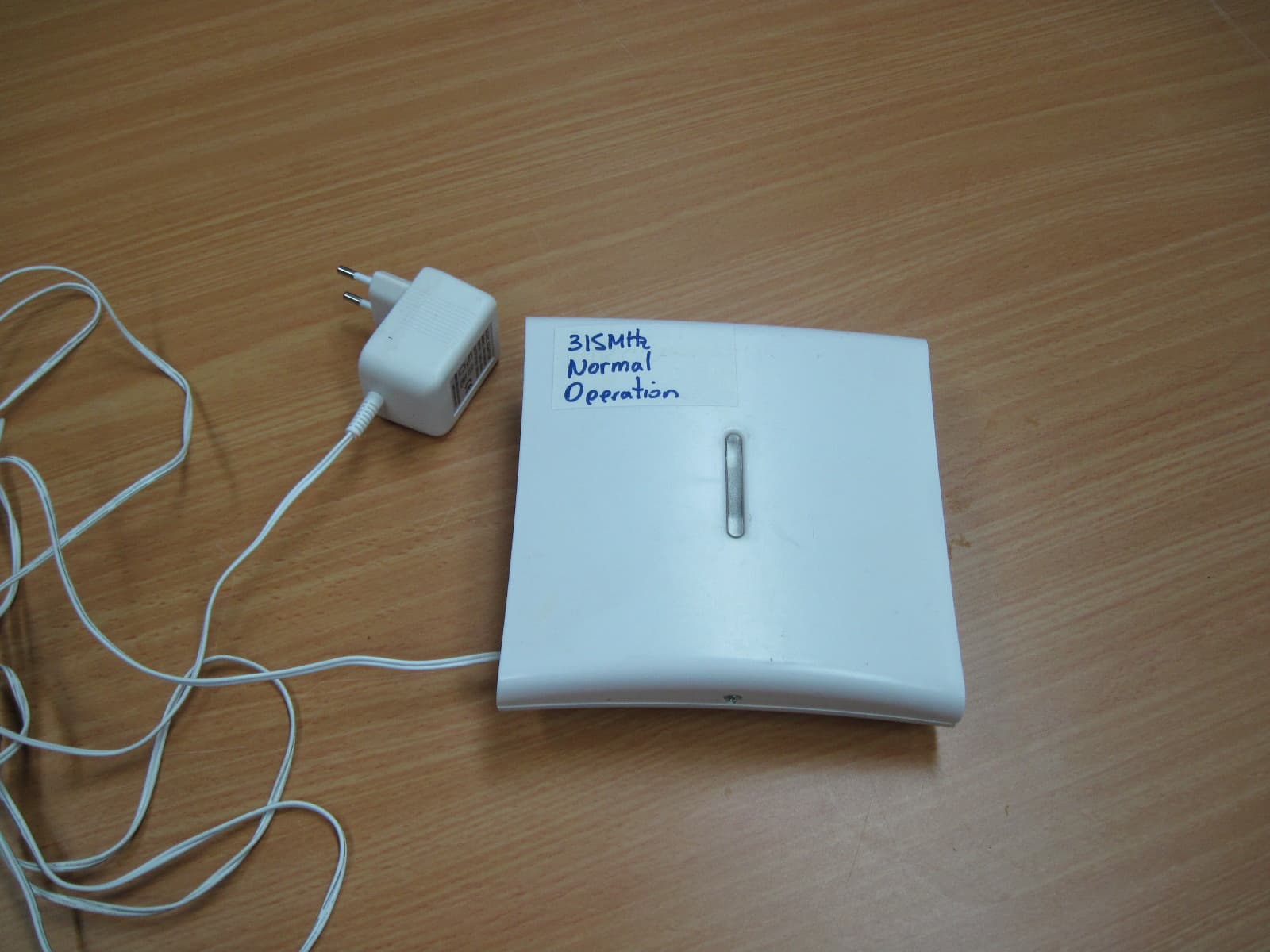
Click to zoom
Application Details
- Equipment Class
- DSR - Part 15 Remote Control/Security Device Transceiver
- Date of Grant
- Sep 05, 2010
- Application Purpose
- Original Equipment
- Date of Application
- Sep 01, 2010
- Equipment Note
- WIRELESS REPEATER FOR POWER CODE COMMUNICATIONS
- Frequency Range
- 315.00000000 - 315.00000000
- Company
- Visonic Ltd.
- Country
- Israel
Documents & Files
Document Text
Text extracted from the exhibit documents filed with the FCC. Open a document above to read the original.
Users Manual
D-302722 1 MCX-610 Wireless Repeater for PowerCode Communications Installation Instructions 1. INTRODUCTION The MCX-610 is a range extender designed to relay digital data between wireless devices and a control panel. Repeater links are required when the control panel is beyond the range of at least some of the devices and is therefore incapable of receiving transmissions directly (see Figure 1). Devices whose message transmissions need to be repeated by the repeater must be enrolled to the repeater and to the control panel. Features Supports 1way and 2way keyfob and detector devices Mains powered 36 hours backup battery (rechargeable) Front and back tamper protected Enrolment and test buttons Diagnostic of installation performance Power fail indication (greed LED) Activity (RF) indication (blue LED) Compatible with PowerMaxExpress PowerMaxComplete PowerMaxPro, PowerMax+ and PowerMax1 versions Indoor environment Note: MCX-610 does not support wireless sirens and repeater chains. MCX-610 POWERMAX CONTROL PANEL Keyfob Door or window open/close detector Motion detector Two-way Keyfob Smoke detector Figure 1 - Repeater Configuration The MCT-237 2way keyfob is supported by MCX-610 starting from MCT-237 partition version and above. 2. SPECIFICATIONS Frequency Band (MHz): Europe: 868.95 and 433.92 USA & canada: 315 Antenna: Diversity antenna Enrolled devices: Up to 50 devices may be enrolled to the repeater. Communication Protocol: PowerCode AC Power Supply: AC to AC adaptor. 120 VAC, 60 Hz / 9 VAC, 0.35 A min. (in the U.S.A.) 230 VAC, 50 Hz / 9 VAC, 0.35 A min. For Europe: Unit shall be powered by 9VAC only by suitably rated (min. 0.35A rated output, 49°C permitted ambient) SELV (safety extra low voltage) Limited Power Source (LPS) AC/AC transformer. Backup Battery: 4.8-Volt 1300 mAh NiMH rechargeable. Caution: Risk of explosion if battery is replaced by an incorrect type. Dispose of used batteries according to the manufacturer's instructions. Current drain at 5.7 VDC: 90 mA Battery Backup Duration (with fully charged 1300 mA/h battery) 36 hours: LED indicator: Green LED lights when AC power on. Blue LED lights during transmission. Supervision: A periodic supervision message is transmitted automatically once every 15 minutes at 433.92 and 868.95 MHz and once every hour at 315 MHz. Complies with Standards: Europe CE: EN 300220, EN 301489, EN 50130-4, EN 60950 USA: CFR 47 part 15, Canada: RSS 210 Operating Temperature: 0°C to 49°C (32°F to 120°F). Dimensions (H x W x D): 161x161x50mm (6-7/16 x 6-7/16 x 1-3/4 in) Weight: (with battery): 470g (16.5 oz.) 3. FUNCTION 3.1 Service Messages In addition to repeating messages of enrolled devices, the MCX-610 generates the following event codes automatically: Low Battery Tamper Supervision. 3.2 Indications Green LED: lights when AC power is available Blue LED: lights during transmission 2 D-302722 4. INSTALLATION 4.1 Repeater's Location Selection A. Install the repeater where good communication is assured with the PowerMax panel or alternative target receiver and with the transmitters deployed in the repeater's coverage area B. Make sure the repeater is mounted as high as possible above the floor and well away from metal chimneys, large metal cabinets, metal doors and reinforced concrete walls, all of which may reduce the communication range. C. Make sure that the location you have selected is near an electrical outlet. D. Mount the repeater in the selected location as shown in Figure 3. 4.2 Battery Pack Insertion Note: The rechargeable backup battery must be connected before connecting to AC mains power. If the backup battery is not connected or if a low battery condition exists when the cover is opened the repeater will beep every 10 seconds. Note: Battery replacement should be done by a service man. TURN & PUSH BATTERY BATTERY CABLE BATTERY TEST BUTTON CONNECT THE WIRES OF THE AC ADAPTER TO THE TERMINAL BLOCK ENROLL BUTTON AC CONNECTOR TERMINAL BLOCK BATTERY PACK CONNECTOR AC ADAPTER CONNECTOR Figure 2 - Battery Pack Insertion 1 2 3 (*) 4 For back tamper screw 6 5 AC to AC adaptor Figure 3 - Installation 4.3 Adding Devices Devices whose message transmissions need to be repeated by the repeater must be enrolled both to the repeater and to the control panel. A total of 50 devices may be enrolled to the MCX- 610. Follow the instructions below for enrolling a device. A. Remove the MCX-610 cover. B. Press the repeater’s enroll button and release it (see Figure 2); the orange LED blinks for 10 sec. Note: Do not press the enroll button for longer than 3 sec. C. Initiate transmission from the device to be enrolled within 10 seconds. In response, the green LED will light and a "happy" beep will sound to indicate successful enrollment of the device. Note: For enrollment verification, the blue LED will blink when the device is activated. D. Repeat steps A to C for enrolling additional devices. Notes: i) If the device was already enrolled in the MCX-610 and the enroll procedure is performed again for the same device to the same MCX-610, the red LED will light and a "sad" failure beep will sound. ii) In the event that enrollment is performed after 50 devices have already been enrolled, the green LED does not light and a "sad" failure beep will sound. iii) If no transmission has been initiated for more than 10 seconds, the orange LED will extinguish and a double beep will sound. iv) Device enrollment cannot be used to link repeaters. 4.4 Deleting Devices Caution! Deleting devices procedure must be performed without the cover. D-302722 3 The procedure for deleting devices enrolled to the repeater is performed for all the devices collectively. It is not possible to clear a specific device from the MCX-610 memory. A. Remove the MCX-610 cover. B. Press the repeater’s enroll button continuously. In response, the following successive stages should be observed: i) The orange LED blinks and the buzzer beeps at a slow rate (3 sec.). ii) The red LED blinks and the buzzer beeps…
Text truncated - open the document above for the full version.
Cover Letter(s)
Federal Communications Commission Authorization and Evaluation Division Subject: Confidentiality Request regarding application for certification of FCC ID: WP3MCX610 29 August 2010 Dear Sirs Pursuant to Sections 0.457 and 0.459 of the Commission’s Rules, we hereby request confidential treatment of information accompanying this application as outlined below: CONF APPENDIX MCX-610 Schem.pdf CONF APPENDIX MCX-610 PartsLst.pdf CONF APPENDIX MCX-610 BlkDia.pdf The above materials contain trade secrets and proprietary information not customarily released to the public. The public disclosure of these materials may be harmful to the applicant and provide unjustified benefits to its competitors. The applicant understands that pursuant to Section 0.457 of the Rules, disclosure of this application and all accompanying documentation will not be made before the date of the Grant for this application. Sincerely, Arick Elshtein
Cover Letter(s)
29 August 2010 To: Timco Engineering Inc. To Whom It May Concern We hereby authorize Shaike Raz of ITL to act on the behalf of Visonic Ltd, regarding the FCC ID Certification process for the following applications Unit Name /Model: MCX-610 FCC ID: WP3MCX610 Thank you, Arick Elshtein
Cover Letter(s)
29 August 2010 Letter of individual Authorization to sign Form 731 To: Timco Engineering Inc. To Whom It May Concern We hereby authorize Shaike Raz of ITL as an authorized individual to sign for form 731 in the favor of FCC ID : WP3MCX610 application. Thank you, Arick Elshtein International Standards Manager
ID Label/Location Info
ECM Title: VISONIC LABEL DRAWING VISONIC LTD. 13739 Product Name: LABEL MCX-610 FCC Date Name Document No: 4008987 23.08.10 YANA K. Created Document Rev: 00 Updated Sheet 1 of 1 23.08.10 MICHA F. Approved MATERIAL: PVC S-0002-A SIZE: 65 X 40 mm NOTES: Description MFG- Variable (Product description) 90-ZZZZZZ- Variable (Product cat.no) A- Variable (Product revision) WW- Week of Year YY- Year XXXXXX- Numerator (increment by 1, became equal to 000001 every new week)
Operational Description
The MCX-610 is a range extender designed to relay digital data between wireless devices and a control panel. Repeater links are required when the control panel is beyond the range of at least some of the devices and is therefore incapable of receiving transmissions directly (see diagram below). Devices whose message transmissions need to be repeated by the repeater must be enrolled to the repeater and to the control panel. Features • Supports 1way and 2way keyfob and detector devices • Mains powered • 36 hours backup battery (rechargeable) • Front and back tamper protected • Enrolment and test buttons • Diagnostic of installation performance • Power fail indication (greed LED) • Activity (RF) indication (blue LED) • Compatible with PowerMaxExpress PowerMaxComplete PowerMaxPro, PowerMax+ and PowerMax1 versions • Indoor environment Note: MCX-610 does not support wireless sirens and repeater chains. MCX-610 POWERMAX CONTROL PANEL Keyfob Door or window open/close detector Motion detector Two-way Keyfob Smoke detector
Parts List/Tune Up Info
29 August 2010 Reviewing Engineer Subject: Tune-up Procedure for Wireless Repeater for Power Code Communications M/N MCX-610 FCC ID: WP3MCX610 IC: 1467C-MCX610 To Whom it may Concern, I hereby declare that there is no tune-up procedure for the subject product. Sincerely, Arick Elshtein
Test Report
DATE: 01 September 2010 I.T.L. (PRODUCT TESTING) LTD. FCC Radio Test Report for Visonic Ltd. Equipment under test: Wireless Repeater for Power Code Communications MCX-610 (PCI) (315 MHz) Written by: _____________________________ D. Shidlowsky, Documentation Approved by: _____________________________ A. Sharabi, Test Engineer Approved by: _____________________________ I. Raz, EMC Laboratory Manager This report must not be reproduced, except in full, without the written permission of I.T.L. (Product Testing) Ltd. This report relates only to items tested. Test Report E99067.01 Visonic Ltd. Page 1 of 46 FCC ACC M Ver 1.1 05Mayl 2000 Test Report E99067.01 Visonic Ltd. Page 2 of 46 FCC ACC M Ver 1.1 05Mayl 2000 Measurement/Technical Report for Visonic Ltd. Wireless Repeater for Power Code Communications MCX-610 (PCI) (315 MHz) FCC ID: WP3MCX610 IC No.: 1467C-MCX610 This report concerns: Original Grant: x Class I change: Class II change: Equipment type: Part 15 Security/Remote Control Transceiver 47CFR15 Section 15231 (a-d) Measurement procedure used is ANSI C63.4-2003. Application for Certification Applicant for this device: prepared by: (different from "prepared by") Ishaihou Raz Arik Elshtein ITL (Product Testing) Ltd. Visonic Ltd. Kfar Bin Nun 24 Habarzel St. D.N. Shimshon 99780 Tel-Aviv 69710 Israel Israel e-mail [email protected] Tel: +972-3 -645-6789 Fax: +972-3-645-6788 e-mail: [email protected] TABLE OF CONTENTS 1. GENERAL INFORMATION ------------------------------------------------------------------------------- 5 1.1 Administrative Information ................................................................................. 5 1.2 List of Accreditations ......................................................................................... 6 1.3 Product Description ........................................................................................... 7 1.4 Test Methodology .............................................................................................. 7 1.5 Test Facility ....................................................................................................... 7 1.6 Measurement Uncertainty ................................................................................. 8 2. SYSTEM TEST CONFIGURATION --------------------------------------------------------------------- 9 2.1 Justification ........................................................................................................ 9 2.2 EUT Exercise Software ..................................................................................... 9 2.3 Special Accessories .......................................................................................... 9 2.4 Equipment Modifications ................................................................................... 9 2.5 Configuration of Tested System ........................................................................ 9 3. CONDUCTED AND RADIATED MEASUREMENT TEST SET-UP PHOTO ----------------10 4. CONDUCTED EMISSION DATA -----------------------------------------------------------------------11 4.1 Test Specification ............................................................................................ 11 4.2 Test Procedure ................................................................................................ 11 4.3 Measured Data ................................................................................................ 11 4.4 Test Instrumentation Used, Conducted Measurement ................................... 16 5. AVERAGE FACTOR CALCULATION ----------------------------------------------------------------17 5.1 Test Instrumentation Used .............................................................................. 20 6. PERIODIC OPERATION ---------------------------------------------------------------------------------21 6.1 Specification .................................................................................................... 21 6.2 Requirements .................................................................................................. 21 6.3 Results............................................................................................................. 21 7. FIELD STRENGTH OF FUNDAMENTAL ------------------------------------------------------------25 7.1 Test Specification ............................................................................................ 25 7.2 Test Procedure ................................................................................................ 25 7.3 Measured Data ................................................................................................ 25 7.4 Test Instrumentation Used, Field Strength of Fundamental ........................... 29 8. SPURIOUS RADIATED EMISSION, 9 KHZ – 30 MHZ -------------------------------------------30 8.1 Test Specification ............................................................................................ 30 8.2 Test Procedure ................................................................................................ 30 8.3 Measured Data ................................................................................................ 30 8.4 Test Instrumentation Used, Radiated Measurements .................................... 31 8.5 Field Strength Calculation ............................................................................... 31 9. SPURIOUS RADIATED EMISSION, 30 MHZ – 3500 MHZ --------------------------------------32 9.1 Test Specification ............................................................................................ 32 9.2 Test Procedure ................................................................................................ 32 9.3 Test Data ......................................................................................................... 33 9.4 Test Instrumentation Used, Radiated Measurements .................................... 35 10. BANDWIDTH --------…
Text truncated - open the document above for the full version.
Contact Information
Applicant
Zuri Rubin(Certification Manager)
Test Firm
Israel Testing LaboratoriesIIan Cohen
Technical Specifications
| # | Rule Parts | Frequency Range | Power Output |
|---|---|---|---|
| 1 | 15.231 | 315 MHz - 315 MHz | - |
Other Applications from Visonic Ltd.
WP3NEXTCAMPGP
Dec 21, 2023Wireless Motion detector with integrated camera
Equipment Class
DSS - Part 15 Spread Spectrum Transmitter
WP3RP600PGP
May 16, 2023Wireless Repeater for PowerG Communications
Equipment Class
DSS - Part 15 Spread Spectrum Transmitter
WP3PGMODIQREM
Jun 02, 2021Power-G Modem iQ Remote
Equipment Class
DSS - Part 15 Spread Spectrum Transmitter
WP3SD304EPG2
Jan 03, 2021PowerG Wireless Shock Detector
Equipment Class
DSS - Part 15 Spread Spectrum Transmitter
WP3MP843
Jun 30, 2020PIR detector ZigBee
Equipment Class
DTS - Digital Transmission System