WP3RFDPG2 RF Module, RFD
Visonic Ltd.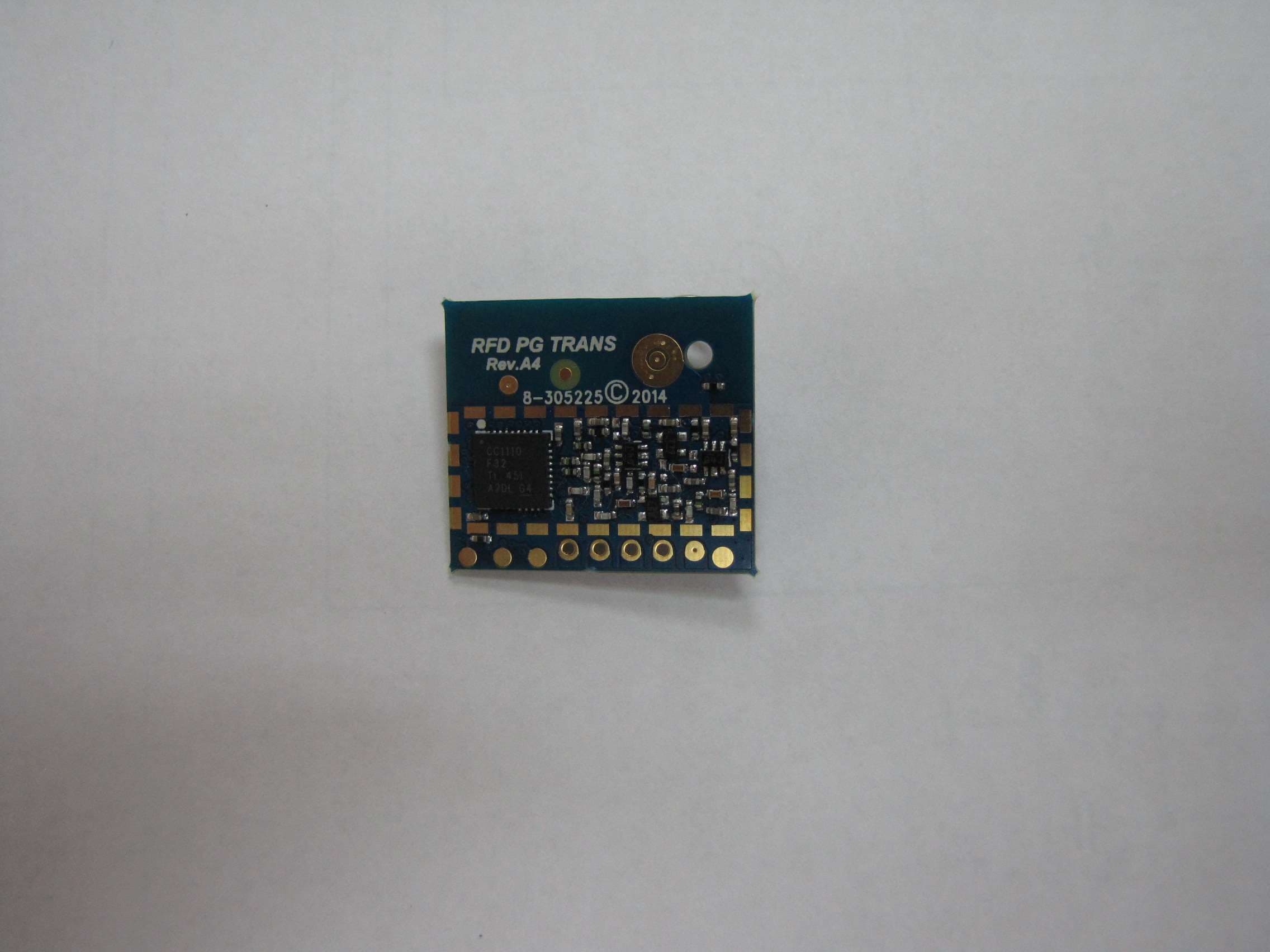
Click to zoom
Application Details
- Equipment Class
- DSS - Part 15 Spread Spectrum Transmitter
- Date of Grant
- Dec 21, 2014
- Application Purpose
- Original Equipment
- Date of Application
- Dec 21, 2014
- Equipment Note
- PG2 RF Module, RFD
- Frequency Range
- 912.75000000 - 919.10600000
- Company
- Visonic Ltd.
- Country
- Israel
Documents & Files
Document Text
Text extracted from the exhibit documents filed with the FCC. Open a document above to read the original.
Users Manual
D-302413 NEXT PG2, NEXT K9-85 PG2 Installation Instructions 1 NEXT PG2 / NEXT K9-85 PG2 PowerG, Wireless, PIR /Pet Tolerant Motion Detector Installation Instructions 1. INTRODUCTION The Next PG2 and Next K9-85 PG2 are 2-way, microprocessor-controlled, wireless digital PIR detectors. The detectors features are as follows: For use with all PowerMaster® control panels (version 10 and higher). Combined Fresnel and cylindrical optics, up to 15 meters (49 ft). The Next PG2 includes wall creep zone protection. In Next PG2 and Next K9-85 PG2, Target Specific Imaging™ (TSI) technology is used for distinction between human beings and pets weighing up to 38 kg (85lb). Includes a fully supervised PowerG transceiver. The advanced True Motion Recognition™ algorithm (patented) allows distinguishing between the true motion of an intruder and any other disturbances which may cause false alarms. Sophisticated frequency domain digital signal processing. Built-in link quality indicators; no need for the installer to physically approach the control panel thus making installation faster and easier. B A A. LED B. Lens Figure 1: External View No vertical adjustment is needed. Motion event counter determines whether 1 or 2 consecutive motion events will trigger an alarm. Automatic termination of walk-test after 15 minutes. Microprocessor-controlled temperature compensation. Sealed chamber protects the optical system. Front cover and back tamper switches, for improved tamper protection. White light protection. Notes: 1. The pet immunity feature was not evaluated by UL. 2. For CE installations, the pet immunity was not evaluated by DNV. 2. INSTALLATION 2.1 General Guidance (see Fig. 2) 1. Keep away from heat sources. 2. Do not expose to air drafts. 3. Do not install outdoors. 4. Avoid direct sunshine. 5. Keep wiring away from power cables. 6. Do not install behind partitions. 7. Mount on solid stable surface. 8. Installed in accordance with NEC, NFPA 70. 9. Installed in accordance with UL 681, Standard for Installations and Classifications of burglar and Holdup Alarm Systems. 123 456 7 Figure 2. General Guidelines Important! The Next K9-85 PG2 detector is tolerant to 38 kg (85 lb) animals moving on the floor or climbing on furniture as long as the activity takes place below 1 m (3 ft). Above the 1 m (3 ft) height limit, the detector is tolerant to 19 kg (42 lb) pets, but the pet immunity will decrease as the pet gets closer to the detector. It is therefore recommended to select a mounting location that minimizes potential close proximity of animals. WARNING! To comply with FCC and IC RF exposure compliance requirements, the PIR detector should be located at a distance of at least 20 cm from all persons during normal operation. The antennas used for this product must not be co-located or operated in conjunction with any other antenna or transmitter 2 D-302413 NEXT PG2, NEXT K9-85 PG2 Installation Instructions 2.2 Mounting (see Fig. 3) Notes: 1. Mount the detector so that its orientation is perpendicular to the expected intrusion path. 2. For installations of detector at 2m high, Dead zone is 2ft at 0m high and 0.5ft at 1.5m high. 1 2 3 B A 4 CD 1. Release screw and remove cover. 2. Push catch and remove board. 3. Insert battery. 4. Mounting A. Front Tamper switch B. Back Tamper switch. C. On surface D. In corner Caution! Risk of explosion if battery is replaced by an incorrect type. Dispose of used battery according to manufacturer's instructions. Note: Back Tamper must be enabled for UL installations.Figure 3. Mounting 2.3. Enrollment Refer to the PowerMaster panel's Installer Guide and follow the procedure under the "02:ZONES/DEVICES" option of the Installer Menu. A general description of the procedure is provided in the following flow chart. Step 1 Step 2 Step 3 Step 4 Step 5 Step 6 Enter the Installer menu and select “02:ZONES/DEVICES” Select "ADD NEW DEVICE" Option See Note [1] Enroll the device or Enter the device ID Select the desired Zone Number Configure Location, Zone Type & Chime Parameters Configure the Detector means scroll and select See Note [2] Notes: [1] If the detector is already enrolled you can configure the detector parameters via the “Modify Devices” option – see Step 2. [2] Select the "Device Settings" option and refer to section 2.4 to configure the detector parameters. 2.4. Configuring the Detector Parameters Enter the menu and follow the configuration instructions for the Next PG2 / Next K9-85 PG2 PIR detector as described in the following table. Option Configuration Instructions Here you determine whether or not the alarm LED indication will be activated. Optional settings: LED ON (default) and LED OFF. Here you determine whether an alarm will be activated upon continued motion (low sensitivity) or upon a single alarm event (high sensitivity).. Optional settings: LOW sensitive (default) and HIGH sensitive. Here you determine whether or not to set the activity time during disarm. Optional settings: NOT Active (default), YES – no delay, YES + 5s delay, YES + 15s delay, YES + 30s delay, YES + 1m delay, YES + 2m delay, YES + 5m delay, YES + 10m delay, YES + 20m delay and YES + 60m delay. DISARM Activity Event Counter Alarm LED DEVICE SETTINGS Z14.DEV SETTINGS Z14.SET CHIME Z14.ZONE TYPE Z14.LOCATION ID No. 120-XXXX Z14:Motion Sens ENTR ID:XXX-XXXX ENROLL NOW or MODIFY DEVICES ADD NEW DEVICES 02.ZONES/DEVICES D-302413 NEXT PG2, NEXT K9-85 PG2 Installation Instructions 3 3. LOCAL DIAGNOSTICS TEST NOTE: Run a diagnostic test at least once a year to ensure that the detector is working correctly. A. Separate the base from the cover (see Fig. 3). B. Put back the cover to return the tamper switch to its normal (undisturbed) position, and then secure the front cover to the base with the case closure screw. C. The Next PG2 / Next K9-85 PG2 will enter a 2 min. stability period. During this time the red LED blinks. D. Walk-test the coverage area - …
Text truncated - open the document above for the full version.
Cover Letter(s)
Visonic Ltd. 24 Habarzel Street P.O.Box 22020 Tel-Aviv 69710, Israel Tele: +972 3 645 6789 Fax: +972 3 645 6788 www.visonic.com Date: 09 September 2014 Federal Communications Commission Authorization and Evaluation Division Subject: Confidentiality Request regarding application for certification of FCC ID: WP3RFD Dear Sirs Pursuant to Sections 0.457 and 0.459 of the Commission’s Rules, we hereby request confidential treatment of information accompanying this application as outlined below: CONF APPENDIX RFD Schem.pdf CONF APPENDIX RFD PartsLst.pdf CONF APPENDIX RFD BlkDia.pdf The above materials contain trade secrets and proprietary information not customarily released to the public. The public disclosure of these materials may be harmful to the applicant and provide unjustified benefits to its competitors. The applicant understands that pursuant to Section 0.457 of the Rules, disclosure of this application and all accompanying documentation will not be made before the date of the Grant for this application. Sincerely, Arick Elshtein Certification Engineer
Cover Letter(s)
Visonic Ltd. 24 Habarzel Street P.O.Box 22020 Tel-Aviv 69710, Israel Tele: +972 3 645 6789 Fax: +972 3 645 6788 www.visonic.com 09 September 2014 To: Timco Engineering Inc. To Whom It May Concern We hereby authorize Shaike Raz of ITL to act on the behalf of Visonic Ltd, regarding the FCC ID Certification process for the following application: FCC ID: WP3RFD Thank you, Arick Elshtein Certification Engineer
Cover Letter(s)
Visonic Ltd. 24 Habarzel Street P.O.Box 22020 Tel-Aviv 69710, Israel Tele: +972 3 645 6789 Fax: +972 3 645 6788 www.visonic.com 08 September 2014 Form 731 Signature Authorization Letter To: Timco Engineering Inc. To Whom It May Concern We hereby authorize Shaike Raz of ITL as an authorized individual to sign for Form 731 on behalf of Visonic Ltd for the FCC ID: WP3RFD application. Thank you, Arick Elshtein Certification Engineer
Cover Letter(s)
Visonic Ltd. 24 Habarzel Street P.O.Box 22020 Tel-Aviv 69710, Israel Tele: +972 3 645 6789 Fax: +972 3 645 6788 www.visonic.com Date: 18 September, 2014 Ref: LMA Compliance Letter To: Federal Communications Commission Subject: LMA compliance letter This letter introduces Visonic’s request to approve its PG2 RF Module model: RFD according to FCC Limited Modular Approval procedure, and to demonstrate the means to control the module as required by the LMA procedure. The RFD Transceiver is based on the CC1110Fx/CC1111Fx , which is is a true low-power sub- 1 GHz system-on-chip (SoC) designed for lowpower wireless applications. The CC1110Fx/CC1111Fx combines the performance of the state-of-the-art RF transceiver CC1101 with an industry-standard enhanced 8051 MCU, up to 32 kB of in-system programmable flash memory and up to 4 kB of RAM. This model is not sold separately, and is not installed in any units other than Visonic’s products. The module is currently used in the following hosts: Next PG2/Next K9-85 PG2, Next CAM PG2/Next CAM K9-85 PG2 and TOWER-30AM PG2/ TOWER-30AM K9-90 PG2. In any case where the PG2 RF Module model: RFD will be added to other hosts in the future, Visonic will expand the LMA to include the new hosts. Since the module incorporates an integral antenna its EIRP does not change between the hosts other than changes created by the host units shape influence. Due to all the above mentioned, Visonic feels that the testing conducted by ITL to the various hosts, with the fact that Visonic has full control on the sales and installation of the module, assure complete compliance with FCC LMA procedure. As per § 15.212 Modular transmitters: Single modular transmitters must meet the following requirements to obtain a modular transmitter approval. Requirement Not Maintained Maintained (1) The radio elements of the modular transmitter must have their own shielding. The physical crystal and tuning capacitors may be located external to the shielded radio elements. The RFD module is not shielded (2) The modular transmitter must have buffered modulation/data inputs (if such inputs are provided) to ensure that the module will comply with part 15 requirements under conditions of excessive data rates or over- modulation. Yes (3) The modular transmitter must have its own power supply regulation. Using BAT (4) The modular transmitter must comply with the antenna and transmission system requirements of §§15.203, 15.204(b) and 15.204(c). The antenna must either be permanently attached or employ a “unique” antenna coupler (at all connections between the module and the antenna, including the cable). The “professional installation” provision of §15.203 is not applicable to modules but can apply to limited modular approvals under paragraph (b) of this section. Yes The RFD Module have integrated antenna As per § 15.212 Modular transmitters: Single modular transmitters must meet the following requirements to obtain a modular transmitter approval. Requirement Not Maintained Maintained (5) The modular transmitter must be tested in a stand-alone configuration, i.e. , the module must not be inside another device during testing for compliance with part 15 requirements. Unless the transmitter module will be battery powered, it must comply with the AC line conducted requirements found in §15.207. AC or DC power lines and data input/output lines connected to the module must not contain ferrites, unless they will be marketed with the module (see §15.27(a)). The length of these lines shall be the length typical of actual use or, if that length is unknown, at least 10 centimeters to insure that there is no coupling between the case of the module and supporting equipment. Any accessories, peripherals, or support equipment connected to the module during testing shall be unmodified and commercially available (see §15.31(i)). The RFD Module always assembled to other host MB (Detector) (6) The modular transmitter must be equipped with either a permanently affixed label or must be capable of electronically displaying its FCC identification number. The labels display in MB (Detector) (7) The modular transmitter must comply with any specific rules or operating requirements that ordinarily apply to a complete transmitter and the manufacturer must provide adequate instructions along with the module to explain any such requirements. A copy of these instructions must be included in the application for equipment authorization. Shows In the manual (8) The modular transmitter must comply with any applicable RF exposure requirements in its final configuration. Tested by ITL in accordance with requirements Thank you, Arick Elshtein Certification Engineer
External Photos
TOWER 30 AM PG2/TOWER 30 AM K9-90 PG2 NEXT CAM PG2/NEXT CAM K9-85 PG2 NEXT PG2/NEXT K9-85 PG2
ID Label/Location Info
TOWER 30 AM PG2/TOWER 30 AM K9-90 PG2 NEXT CAM PG2/NEXT CAM K9-85 PG2 Label Location LABEL LOCATION NEXT PG2/NEXT K9-85 PG2 Label Location
ID Label/Location Info
W W YYXXXXXX S/N: ID:TTT-dddd Residential Intrusion Detection Unit Freq. 915 MHz Equipment 3KES Model:NEXT K9-85 PG2 (915-0:012) P/N:90-203945 Contains FCC ID: W P3RFD IC: 1467C-RFD Installation Instr.: No D-302413 S-203970 REV.03 ARG-H11575 3814139578 S/N: ID:120-2191 Residential Intrusion Detection Unit Freq. 915 MHz Equipment 3KES Model:NEXT PG2 (915-0:012) P/N:90-203642 Contains FCC: W P3RFD IC: 1467C-RFD Installation Instr.: No D-302413 S-203970 REV.04 ARG-H11575 W W YYXXXXXXS/N: S-203972 REV.06 P/N:90-204043 Model:NEXT CAM K9-85 PG2 (915-0:014) L ID:TTT-dddd Contains FCC ID: WP3RFD IC: 1467C-RFD BATT: PACK 2X3V TYPE CR123A Residential Intrusion Detection Unit Installation Instruc.: No D-302893 Rev 4, 1/14 Freq. 915 MHz Equipment 3KES ARG H-11582 3814139501 S/N: S-203972 REV.05 P/N:90-204049 Model:NEXT CAM PG2 (915-0:014) 3YR ID:140-2190 Contains FCC: WP3RFD IC: 1467C-RFD BATT: PACK 2X3V TYPE CR123A Residential Intrusion Detection Unit Installation Instruc.: No D-302893 Freq. 915 MHz Equipment 3KES ARG H-11582 W W YYXXXXXX S/N: S-204991 REV.03 P/N:90-205749 Model:TOWER 30 AM K9-90 PG2 (915-0:012) ID:TTT-dddd Installation Instruc.: No D-303372 Contains FCC ID: WP3RFD IC: 1467C-RFD Equipment 3KES Residential Intrusion Detection Unit Freq. 915 MHz ARG-H11577 3814139810 S/N: S-204991 REV.03 P/N:90-204233 Model:TOWER 30 AM PG2 (915-0:012) ID:123-2373 Installation Instruc.: No D-303372 Contains FCC ID: W P3RFD IC: 1467C-RFD Equipment 3KES Residential Intrusion Detection Unit Freq. 915 MHz ARG-H11577
ID Label/Location Info
Visonic Ltd. 24 Habarzel Street P.O.Box 22020 Tel-Aviv 69710, Israel Tele: +972 3 645 6789 Fax: +972 3 645 6788 www.visonic.com Date: 09 September 2014 Attn: Reviewing Engineer Federal Communications Commission 7435 Oakland Mills Road Columbia, MD 21046 To Whom It May Concern: The Visonic Ltd., PG2 RF Module, FCC ID: WP3RFD, and label are so small that it cannot include the statement specified in FCC Part 15 Sub-part A, Section 15.19 (a) (3) “This device complies with Part 15 of the FCC Rules. Operation is subject to the following two conditions: (1) This device may not cause harmful interference and (2) This device must accept any interference received, including interference that may cause undesired operation." Due to this reason, we are using the provisions of Part 15 Sub-part A, Section 15.19 (a) (5) and this statement appears in a prominent location in the user manual. The unit is so small that the FCC label cannot appear on the device itself and the label appears in all host user manuals. Please contact me if there is any information you may need. Thank you, Arick Elshtein Certification Engineer
ID Label/Location Info
Visonic Ltd. M/N: RFD FCC ID: WP3RFD IC: 1467C-RFD
Internal Photos
TOWER 30 AM PG2/TOWER 30 AM K9-90 PG2 NEXT CAM PG2/NEXT CAM K9-85 PG2 NEXT PG2/NEXT K9-85 PG2
Operational Description
1. Compliance with 15.247(a)(1): 1. The system is a star-topology, time-synchronized network. 2. The timeline of the network is divided into time-slots. The duration of one time-slot is 15.6 milisecond. This means that there are 64 time-slots every second 3. At the beginning of every time-slot, every element of the network (i.e. network-coordinator and all end-nodes) calculates the proper frequency channel for that time-slot. This means that system switches frequency channel 64 times every second. 4. Every element in the network (network-coordinator and all end-nodes) calculates the proper frequency channel in the following way: 1. The system clock is first AES-128 encrypted. Then the proper frequency channel is derived as a function of the encrypted system clock 2. Since the system clock rolls over every 1.5 days, the hopping sequence is 1.5 days long 3. Since the frequency channel number is a function of the encrypted system clock (and since the system clock changes constantly) the hopping sequence is both pseudo-random and evenly distributed (this is a fundamental concept in encryption theory, otherwise, the encryption would have been useless). Evenly distributed frequency hopping sequence means that each frequency is used equally on the average by each transceiver 5. The bandwidth of a frequency channel (and hence the receiver bandwidth) is set to ~130KHz. The bandwidth is selected to be ~130KHz to accommodate ~100KHz signal bandwidth (50kbps, GFSK modulation and 25KHz deviation yields an effective bandwidth of ~100KHz and 20dB bandwidth of ~129KHz) 6. I'm attaching a file with an example of the hopping sequence. The channels are numbered 0 to 49 (i.e. 50 channels). I captured ~4500 hops. 2. Compliance with 15.247(g) and 15.247(h): 1. The system is a star-topology, time-synchronized, time-slotted network 2. The system comprises one network-coordinator (control panel) and multiple end-nodes (devices). 3. Each end-node has an attached sensor. The end-node wakes up periodically (typically every 10s seconds) and samples the sensor. After sampling the sensor, the end-node selects the next available time-slot and transmits a short burst (message) comprising the data sampled from the sensor (the message is less than one time-slot length, i.e. less than 15.6 milisecond length) 4. The short burst is sent at the proper frequency channel, the one associated with the time-slot in which the message is sent 5. The system uses 50 frequency channels. The hopping sequence is 1.5 days long, and since it derived as a function of the encrypted system clock it is both pseudo-random and evenly distributed. Over time, both transmissions from a certain end-node and the overall transmissions from all end-nodes are both pseudo-random and evenly distributed. 6. No coordination of frequency hopping systems, in any manner, for the express purpose of avoiding the simultaneous occupancy of individual hopping frequencies by multiple transmitters is incorporate in the system Channels 41 48 5 13 13 15 47 9 30 23 15 15 13 43 12 49 23 45 26 36 34 16 15 0 27 48 37 48 1 17 28 12 16 28 46 19 14 46 9 33 30 0 34 30 24 28 8 27 49 6 16 27 32 23 29 45 34 10 49 45 17 4 47 45 34 10 26 27 Page 1 Channels 33 6 4 31 37 9 43 2 5 29 3 18 39 49 38 34 31 41 23 7 48 19 49 3 40 29 27 36 47 15 8 30 27 25 42 24 39 26 35 49 16 41 17 43 16 17 39 7 6 18 4 21 21 12 43 30 29 49 47 21 44 42 15 41 17 49 16 0 Page 2 Channels 2 7 26 38 21 10 24 43 7 13 45 20 26 33 45 44 14 31 45 9 37 48 15 1 16 39 39 41 4 47 42 23 11 24 5 44 9 26 22 15 33 35 12 16 3 15 1 42 23 36 29 43 6 18 48 16 31 32 40 3 5 16 25 11 23 12 9 26 Page 3 Channels 31 32 0 36 45 23 44 34 41 1 7 35 23 13 25 5 35 11 8 24 34 42 16 40 5 19 23 25 3 31 35 37 28 23 18 12 15 31 21 30 49 6 30 28 27 24 42 21 28 38 27 25 11 25 3 40 33 5 28 24 17 5 6 33 12 33 38 14 Page 4 Channels 46 33 5 36 17 11 4 47 7 46 38 34 17 47 9 38 15 3 36 20 1 44 5 48 45 30 12 38 25 5 48 9 39 39 0 43 0 28 34 20 13 13 23 14 46 33 46 20 41 22 32 6 35 10 32 25 18 25 30 7 7 10 16 22 33 43 41 17 Page 5 Channels 39 15 40 2 9 7 10 16 29 45 22 19 2 46 11 6 5 3 16 39 15 12 30 23 33 35 0 10 18 13 30 43 49 18 30 6 17 47 3 25 49 36 12 28 19 49 37 32 48 15 5 15 18 44 13 8 48 6 31 18 34 43 37 22 28 32 47 20 Page 6 Channels 9 49 41 40 34 43 35 1 35 27 37 43 22 37 48 23 5 9 49 3 43 17 17 30 30 19 15 6 38 17 21 3 8 35 35 32 0 42 47 11 8 3 18 9 1 30 10 25 44 35 5 4 23 8 26 8 20 25 25 34 4 45 38 36 24 14 32 44 Page 7 Channels 31 17 33 13 5 29 10 10 31 24 48 41 27 37 43 37 46 47 31 40 14 5 1 28 32 29 40 31 48 0 46 47 10 45 28 25 0 14 32 15 4 37 35 24 36 17 8 19 38 6 13 47 22 43 13 11 46 36 43 22 23 20 2 19 30 2 45 6 Page 8 Channels 14 7 11 37 8 21 42 2 12 37 25 30 0 44 45 7 32 8 37 0 2 1 3 46 24 13 13 0 21 45 13 4 3 28 21 37 25 8 1 47 25 9 1 2 25 22 33 43 18 26 38 23 46 44 7 7 8 46 19 6 42 3 3 10 33 37 16 5 Page 9 Channels 13 13 5 44 32 4 2 44 13 9 24 49 28 34 3 41 15 8 16 34 16 25 40 36 49 48 7 18 35 16 13 5 30 17 10 10 0 5 4 26 19 25 0 4 7 32 19 12 23 20 22 0 14 13 7 49 24 37 48 14 35 47 30 11 30 25 12 44 Page 10 Channels 8 33 0 25 20 5 4 14 38 23 31 44 26 28 6 4 36 49 40 45 9 38 15 6 21 27 21 31 39 19 40 44 34 27 39 15 2 28 49 3 42 44 20 32 30 38 2 31 18 39 3 7 10 45 29 28 16 40 11 24 33 44 1 15 48 6 5 47 Page 11 Channels 34 18 35 8 29 38 39 45 6 0 31 47 20 12 46 25 14 13 29 8 0 29 37 32 46 49 35 40 47 47 48 8 38 3 28 49 39 8 20 7 34 22 36 3 19 46 34 33 5 47 2 22 3 11 2 18 45 30 31 3 35 30 21 2 48 42 0 17 Page 12 Channels 46 23 40 46 47 3 21 43 9 27 34 19 0 18 8 10 10 12 40 30 44 37 0 34 17 46 27 41 44 0 2 1 15 3 47 25 39 33 23 1 47 19 21 13 30 9 11 26 4 38 35 26 5 45 47 31 7 28 13 37 31 6 33 35 21 32 33 13 Page 13 Channels 43 9 26 15 39 45 6 41 15 26 49 45 6 12 24 16 38 37 46 8 19 3 12 43 42 13 8 28 16 17 24 19 43 9 7 40 4 10 46 3 3 6 17 40 13 34 33 24 39 47 29 5 37 36 26 30 17 37 28 25 33 13 36 33 9 3 32 6 Page 14 Channels 24 7 29 3 37 21 47 36 38 32 14 8 30 1 40 48 5 22 4 40 44 38 13 48 47 45 8 29 10 5 19 29 32 33 24 20 15 39 5 29 25 …
Text truncated - open the document above for the full version.
Test Report
Test Report E136050.01 Visonic Ltd. Page 1 of 62 FCC ACC M Ver 1.2 28 February 2011 DATE: 06 November 2014 I.T.L. (PRODUCT TESTING) LTD. FCC Radio Test Report For Visonic Ltd. Equipment under test: PG2 RF Module RFD Written by: _____________________________ R. Pinchuck, Documentation Approved by: _____________________________ M. Zohar, Test Engineer Approved by: _____________________________ I. Raz, EMC Laboratory Manager This report must not be reproduced, except in full, without the written permission of I.T.L. (Product Testing) Ltd. This report relates only to items tested. Test Report E136050.01 Visonic Ltd. Page 2 of 62 FCC ACC M Ver 1.2 28 February 2011 Measurement/Technical Report for Visonic Ltd. PG2 RF Module RFD FCC ID: WP3RFD IC: 1467C-RFD This report concerns: Original Grant: X Class I Change: Class II Change: Equipment type: Frequency Hopping Spread Spectrum Limits used: 47CFR15 Section 15.247 Measurement procedures used are FCC Public Notice DA-00-705 and ANSI C63.4: 2003. Application for Certification Applicant for this device: prepared by: (different from "prepared by") R. Pinchuck Arik Elshtein ITL (Product Testing) Ltd. Visonic Ltd. 1 Bat Sheva Street 24 Habarzel St. Lod, 7116002 Tel-Aviv 69710 Israel Israel e-mail: [email protected] Tel: +972-3 -645-6789 Fax +972-3-645-6788 e-mail: [email protected] Test Report E136050.01 Visonic Ltd. Page 3 of 62 FCC ACC M Ver 1.2 28 February 2011 TABLE OF CONTENTS 1. GENERAL INFORMATION ------------------------------------------------------------------------------- 5 1.1 Administrative Information ................................................................................. 5 1.2 List of Accreditations ......................................................................................... 6 1.3 Product Description ........................................................................................... 7 1.4 Test Methodology .............................................................................................. 7 1.5 Test Facility ....................................................................................................... 7 1.6 Measurement Uncertainty ................................................................................. 8 2. SYSTEM TEST CONFIGURATION --------------------------------------------------------------------- 9 2.1 Justification ........................................................................................................ 9 2.2 EUT Exercise Software ................................................................................... 14 2.3 Special Accessories ........................................................................................ 14 2.4 Equipment Modifications ................................................................................. 14 2.5 Configuration of Tested System ...................................................................... 14 3. RADIATED MEASUREMENT TEST SET-UP PHOTOS -----------------------------------------15 4. 20DB MINIMUM BANDWIDTH -------------------------------------------------------------------------17 4.1 Test Specification ............................................................................................ 17 4.2 Test procedure ................................................................................................ 17 4.3 Test Results..................................................................................................... 17 4.4 Test Equipment Used, 20 dB Minimum Bandwidth ......................................... 19 5. 26DB MINIMUM BANDWIDTH -------------------------------------------------------------------------20 5.1 Test Specification ............................................................................................ 20 5.2 Test procedure ................................................................................................ 20 5.3 Test Results..................................................................................................... 20 5.4 Test Equipment Used, 26 dB Minimum Bandwidth ......................................... 22 6. NUMBER OF HOPPING FREQUENCIES -----------------------------------------------------------23 6.1 Test Specification ............................................................................................ 23 6.2 Test Procedure ................................................................................................ 23 6.3 Test Results..................................................................................................... 23 6.4 Test Equipment Used; Number of Hopping Frequencies ............................... 29 7. CHANNEL FREQUENCY SEPARATION ------------------------------------------------------------30 7.1 Test Specification ............................................................................................ 30 7.2 Test procedure ................................................................................................ 30 7.3 Test Results..................................................................................................... 30 7.4 Test Equipment Used, Channel Frequency Separation Test .......................... 32 8. RADIATED MAXIMUM POWER OUTPUT ----------------------------------------------------------33 8.1 Test Specification ............................................................................................ 33 8.2 Test procedure ................................................................................................ 33 8.3 Test Results..................................................................................................... 34 8.4 Test Equipment Used, Radiated Maximum Power Output ............................. 36 9. DWELL TIME ON EACH CHANNEL ------------------------------------------------------------------37 9.1 Test Specification ............................................................................................ 37 9.2 Test Procedure ..…
Text truncated - open the document above for the full version.
Contact Information
Applicant
Zuri Rubin(Certification Manager)
Test Firm
Israel Testing LaboratoriesIIan Cohen
Technical Specifications
| # | Rule Parts | Frequency Range | Power Output |
|---|---|---|---|
| 1 | 15C | 912.75 MHz - 919.106 MHz | 27.50 mW |
Other Applications from Visonic Ltd.
WP3NEXTCAMPGP
Dec 21, 2023Wireless Motion detector with integrated camera
Equipment Class
DSS - Part 15 Spread Spectrum Transmitter
WP3RP600PGP
May 16, 2023Wireless Repeater for PowerG Communications
Equipment Class
DSS - Part 15 Spread Spectrum Transmitter
WP3PGMODIQREM
Jun 02, 2021Power-G Modem iQ Remote
Equipment Class
DSS - Part 15 Spread Spectrum Transmitter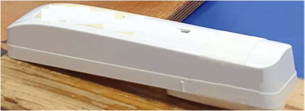
WP3SD304EPG2
Jan 03, 2021PowerG Wireless Shock Detector
Equipment Class
DSS - Part 15 Spread Spectrum Transmitter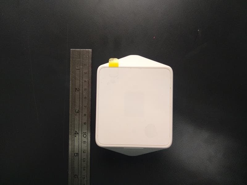
WP3MP843
Jun 30, 2020PIR detector ZigBee
Equipment Class
DTS - Digital Transmission System