WP3ZBTPCA ZBT (2.4 GHz) RF ZIGBEE MODULE
Visonic Ltd.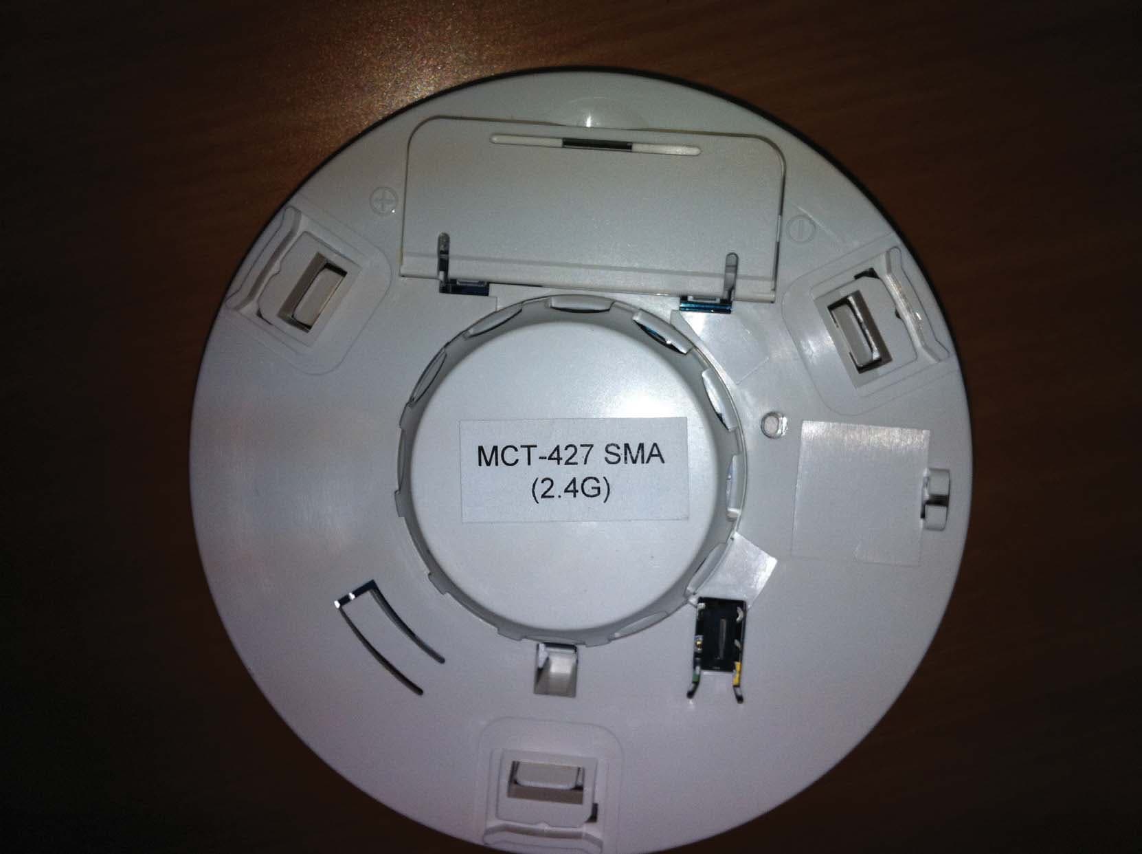
Click to zoom
Application Details
- Equipment Class
- DTS - Digital Transmission System
- Date of Grant
- Dec 19, 2011
- Application Purpose
- Original Equipment
- Date of Application
- Dec 19, 2011
- Equipment Note
- PCA ZBT (2.4 GHz) RF ZIGBEE MODULE
- Frequency Range
- 2405.00000000 - 2475.00000000
- Company
- Visonic Ltd.
- Country
- Israel
Documents & Files
Document Text
Text extracted from the exhibit documents filed with the FCC. Open a document above to read the original.
Users Manual
D-303360 CLIP SMA Installer's Guide 1 CLIP SMA Wireless Curtain-Type Infrared Detector Installation Instructions 1. INTRODUCTION The CLIP SMA is the smallest and most elegant wireless curtain- pattern PIR detector for indoor use and designed for easy installation. Its function is based on new and sophisticated, patented FM data acquisition and digital signal processing. Modern technology is used to include 3 different detectors in a single case, each programmable for optimized performance at the specific mounting location. This results in better catch performance and virtually no false alarms. The superiority in performance of this detector is achieved by applying an improved version of the patented True Motion Recognition™ (TMR) algorithm. This advanced motion analysis method allows the CLIP SMA to distinguish between the true motion of the human body and any other disturbances that cause false alarms. After detection, the detector disarms itself to save battery power. It rearms (reverts to the ready state) if there is no subsequent detection throughout the following 2-minute period. The CLIP SMA includes the following features: Very low current consumption Microprocessor-controlled temperature compensation Sealed chamber protects the optical system Front cover tamper switch White light protection Elegantly styled, sturdy case Detailed coverage patterns and mounting alternatives are illustrated in Figures 2 through 6. Figure 1. CLIP SMA General View Figure 2. Wall-Mount Curtain 2.4m Figure 3. Ceiling-Mount Curtain Figure 4. Overhead Curtain This side up Figure 5. Curtain / Pet Alley OPTION A OPTION B DETECTION CURTAIN Figure 6. CLIP SMA on Internal Doorframe 2. SPECIFICATIONS OPTICAL Detector Type: Dual-element low noise pyroelectric sensor. Number of Curtain Beams: 2 Mounting Positions: See Figures 2 through 6. Range Settings: Long (6 m/18 ft), Medium (4 m/12 ft) and Short (1.2 - 2m/6 ft) (Jumper-selected). ELECTRICAL Internal Battery: 3V Lithium battery, type CR123A. For UL installations, use Panasonic, GP or Sanyo only. Nominal Battery Capacity: 1450 mAh. Battery Life: 3 years (for typical use). Note: Inability to connect with wireless network, or wireless link quality no higher than 20% may significantly reduce the expected battery life. Battery Power Test: Performed immediately upon battery insertion and periodically every several hours. Microprocessor: 8-bit, low power CMOS. FUNCTIONAL Visual Indications (red LED): LED lights for about 3 seconds upon transmission of alarm & tamper messages and upon motion detection in the walk test mode. LED flashes during the power-up stabilization period (approx. 2 min), or after restoring the cover (by pressing the tamper switch). LED does not light upon transmission of supervision messages. Alarm Period: Approx. 3 seconds. Rearm Timer: Rearms the detector 2 minutes after the last alarm. WIRELESS Frequency: 2.4 Ghz as per IEEE 802.15.4 Tamper Alert: Reported when a tamper event occurs and in any subsequent message, until the tamper switch is restored. Supervision Message: Signaling at 24-minute intervals. MOUNTING Height: 1.8 - 2.4 m (6 - 8 ft). See Figures 2 – 6. Installation Options: See Figures 2 – 6. ENVIRONMENTAL Operating Temperature: -10°C to 50°C (14°F to 122°F). Storage Temperature: -20°C to 60°C (-4°F to 140°F). RFI Protection: > 20 V/m to 1000 MHz. Compliance with standards: USA: CFR 47 part 15, Canada: RSS 210 . ANSI/UL 639, ULC – S306 PHYSICAL Dimensions (H x W x D): 105 x 35 x 30 mm (4-1/8 x 1-3/8 x 1-3/16 in.). Weight (with battery): 60 g (2.1 oz). Color: White. PATENTS U.S. Patent 5,693,943 (other patents pending) 2 D-303360 CLIP SMA Installer's Guide 3. INSTALLATION 3.1 General Guidelines Do not install near sources of heating/cooling. Do not aim at windows. Do not install outdoors. Do not install where direct sunlight can strike the unit. Do not install near high- voltage electrical lines. Do not install behind any obstruction. Do not mount on unstable surfaces. 3.2 Regular Mounting FRONT TAMPER SWITCH SENSOR RANGE SELECT JUMPER 3 VOLT LITHIUM BATTERY BACK TAMPER SWITCH (OPTIONAL) RF MODULE LEDS Figure 7. Internal View BREAK- AWAY SEGMENT ATTENTION:The back tamper switch becomes functional only when the break-away segment is secured to the wall with a screw . M O U N T I N G S U R F A C E INSE RT SCREW TO SECURE COVER WITH BASE 4 3 POSITION THE PCB IN ITS PLACE IN THE BASE 1 DRIL L TWO HOLES IN THE MOUNTING SURFACE AND SECURE BASE WITH TWO SCREWS 2 FOR BACK TAMPER (OPTIONAL), DRIL L TWO HOLES AND SECURE WITH TWO SCREW Figure 8. Surface Mounting Notes: 1) After mounting, be sure that no gaps remain in the detector housing, for example, in the area around the screw holes. 2) Remove the battery using your fingers, and not with a screwdriver. 3.3 Bracket Mounting Note: When mounting using the bracket, the back tamper is not functional. D-303360 CLIP SMA Installer's Guide 3 DRILL TWO 7 mm (1/4“) HOLES AT THE MARKED SPOTS Figure 9. Drilling Holes NOTE: THE BRACKET PROVIDES TWO MOUNTING OPTIONS FOR OPTIMUM ANGLE COVERAGE . USE THESE TWO HOLES TO INCREASE THE COVERAGE RANGE BY 5 USE THESE TWO HOLES TO INCREASE THE COVERAGE RANGE BY 10 DRILL TWO HOLES IN THE MOUNTING SURFACE 1 SECURE BRACKET WITH TWO SCREWS 2 * ** Figure 10. Mounting Bracket to Surface PLACE THE LOCKING PLATE OVER THE TWO PINS 2 SECURE THE LOCKING PLATE BY PRESSING DOWNWARD 3 LOCKING PLATE PLACE THE BASE SLOTS OVER THE TWO BRACKET PINS 1 Figure 11. Securing Locking Plate to Base POSITIONTHE PCB CORRECTLY IN THE BASE 1 INSERT SCREWTO SECURE COVER WITH BASE 2 Figure 12. Mounting Cover to Base Note: The CLIP SMA can be mounted on either side of a window. Figure 13. Mounting on Both Sides of a Window 4 D-303360 CLIP SMA Installer's Guide 3.4 Setting the Coverage Range A 4-pin jumper is used to select 3 ranges, according to the type of installation, for the curtain beams (see Figures 2-6 and 15). Short range - approx. 2 m (6 ft) Medium range - app…
Text truncated - open the document above for the full version.
Cover Letter(s)
Date:12December2011 Federal Communications Commission Authorization and Evaluation Division Subject: Confidentiality Request regarding application for certification of FCC ID:WP3ZBT Dear Sirs Pursuant to Sections 0.457 and 0.459 of the Commission’s Rules, we hereby request confidential treatment of information accompanying this application as outlined below: CONF APPENDIXE203826BlkDia.pdf CONF APPENDIX E203826PartsLst.pdf CONF APPENDIX E203826 Schem.pdf The above materials contain trade secrets and proprietary information not customarily released to the public. The public disclosure of these materials may be harmful to the applicant and provide unjustified benefits to its competitors. The applicant understands that pursuant to Section 0.457 of the Rules, disclosure of this application and all accompanying documentation will not be made before the date of the Grant for this application. Sincerely, Arick Elshtein International Compliance Manager Visonic Ltd.
Cover Letter(s)
I.T.L (PRODUCT TESTING) Ltd. PRODUCT SAFETY, EMC & TELECOMS LAB. Bat-Sheva St., POB 87 LOD 71100 ISRAEL Tel. 972-8-9186100 Fax. 972-8-9153101 Email: [email protected], Web Site: http://www.itl.co.il To: Federal Communications Commission From: Shaike Raz Att: Reviewing Engineer Reference No: L107120.00 Date: 19 December 2011 Subject: FCC ID Application for Visonic Ltd. PCA ZBT (2.4 GHz) RF ZigBee Module FCC ID: WP3ZBT To Whom It May Concern: To Whom it may Concern, 1. We are submitting an application for Limited Modular approval on behalf of Visonic Ltd. for the above subject device placed in the hosts whose details are submitted with this application. 2. Exploratory radiated emission test was performed on the host configurations (MCT-302 SMA, Clip SMA, MCT-427 SMA, MCT-550 SMA, MCT-442 SMA, Next Plus Kp-85) in order to determine the “worst case” host. Full testing was performed on the “worst case” host (MCT-427 SMA). 3. Exhibits concerning all hosts under this application are being submitted. 4. The ZigBee Module operates only in the hosts listed above and therefore does not have its own manual. User manuals for all hosts are being submitted as part of the application. 5. Please let me know if you need any additional information. Regards, Shaike Raz EMC Laboratory Manager EMC Laboratory ITL (Product Testing) Ltd. Lod/Kfar Bin Nun Israel Tel: +972-8- 9153100 Ext. 217 Fax: +972-8- 915-3101 Email: [email protected]/[email protected] http://www.itl.co.il
Cover Letter(s)
12December2011 To: Timco Engineering Inc. To Whom It May Concern We hereby authorize Shaike Raz ofITL to act on the behalf ofVisonic Ltd, regarding the FCC ID Certification process for the following application FCC ID:WP3ZBT Thank you, Arick Elshtein International Compliance Manager Visonic Ltd.
Cover Letter(s)
12December2011 Letter of individual Authorization to sign Form 731 To: Timco Engineering Inc. To Whom It May Concern We hereby authorize Shaike Raz ofITL as an authorized individual to signForm 731on behalf of Visonic Ltdfor theFCC ID:WP3ZBTapplication. Thank you, Arick Elshtein International Compliance Manager Visonic Ltd.
Cover Letter(s)
12December2011 attn:Reviewing Engineer Federal Communications Commission 7435 Oakland Mills Road Columbia, MD 21046 To Whom It May Concern: TheE203826 ZigBee transceiver FCC ID: WP3ZBTand labelis so small(2cm x 2 cm)that it cannot include the statement specified in FCC Part 15 Sub-part A, Section 15.19 (a) (3) “This device complies with Part 15 of the FCC Rules. Operation is subject to the following two conditions: (1)This device may not cause harmful interference and (2)This device must acceptany interference received, including interference that may cause undesired operation." Due to this reason, we are using the provisions of Part 15 Sub-part A, Section 15.19 (a) (5) and this statement appears in a prominent location in the user manual. Theunit is so small that the FCC label cannot appear on the device itself and the label appears in all host user manuals. Please contact me if there is any information you may need. Sincerely, Arick Elshtein International Compliance Manager Visonic Ltd.
Cover Letter(s)
Visonic Ltd. 24 Habarzel Street P.O.Box 22020 Tel-Aviv 69710, Israel Tele: +972 3 645 6789 Fax: +972 3 645 6788 www.visonic.com Ref: LMA Compliance Letter To: Federal Communications Commission 15 December 2011 Subject: LMA compliance letter This letter introduces Visonic's request to approve its ZIGBEE module according to FCC Limited Modular Approval procedure, and to demonstrate the means to control the module as required by the LMA procedure. Module description: The module is a small PCB (25 mm X 23 mm) ZIGBEE protocol transceiver @ 2.45 GHZ. This feature is provided by an embedded module IC ZigBee/802.15.5 type EM 357 manufactured by Ember, and a Skyworks 2.4 GHz Transmit/Receive front end with integrated LNA The module is "piggy backed" on the mother board of each detector. The module is not sold separately and is not installed in any unit other than Visonic's products. The module is currently used in the following hosts/Detectors: MCT 302 SMA, Clip SMA. MCT 550 SMA, Next Plus K9-85 SMA, MCT 427 SMA, MCT 442 SMA. Regards Arick Elshtein International Standards Manager Phone: +972 3 6456714 Fax: +972 3 6456788 Mobile: +972 54 6775714 As per § 15.212 Modular transmitters: Single modular transmitters must meet the following requirements to obtain a modular transmitter approval. Requirement Not Maintained Maintained (1) The radio elements of the modular transmitter must have their own shielding. The physical crystal and tuning capacitors may be located external to the shielded radio elements. Not maintained (2) The modular transmitter must have buffered modulation/data inputs (if such inputs are provided) to ensure that the module will comply with part 15 requirements under conditions of excessive data rates or over-modulation. YES (3) The modular transmitter must have its own power supply regulation. Using battery (4) The modular transmitter must comply with the antenna and transmission system requirements of §§15.203, 15.204(b) and 15.204(c). The antenna must either be permanently attached or employ a “unique” antenna coupler (at all connections between the module and the antenna, including the cable). The “professional installation” provision of §15.203 is not applicable to modules but can apply to limited modular approvals under paragraph (b) of this section. YES (Internal Antenna) (5) The modular transmitter must be tested in a stand-alone configuration, i.e. , the module must not be inside another device during testing for compliance with part 15 requirements. Unless the transmitter module will be battery powered, it must comply with the AC line conducted requirements found in §15.207. AC or DC power lines and data input/output lines connected to the module must not contain ferrites, unless they will be marketed with the module (see §15.27(a)). The length of these lines shall be the length typical of actual use or, if that length is unknown, at least 10 centimetres to insure that there is no coupling between the case of the module and supporting equipment. Any accessories, peripherals, or support equipment connected to the module during testing shall be unmodified and commercially available (see §15.31(i)). Not Maintained (The module was tested inside the battery powered Detector) (6) The modular transmitter must be equipped with either a permanently affixed label or must be capable of electronically displaying its FCC identification number. Label is on the detector itself
ID Label/Location Info
Product Name: LABEL MCT-427 SMA FCC PRODUCT VISONIC LTD. Apx 2-1-3 Create:Approved: Document No: 4010040 Doc.Rev.: 01 Sheet No./of: 1/1 Name Date Signature Scale: 100% Title: Stamp and Sticker Drawing Upd ECM 12345 0 CONFIDENTIALThis document contains information whichis proprietary to Visonic Ltd., Israel. Theuse, copy or dissemination of this materialfor any purpose other than that for which itis intended is prohibited without the priorwritten consent of Visonic Ltd.Date Released: To Whom: Zach A. Yana K. 15.06.11 14535 Catalog No.: S-303419 Update: WIRELESS PHOTOELECTRIC HEAT & SMOKE DETECTOR MODEL: MCT-427 SMA(2.4GHz) The sensitivity range is 1%/ft ~ 2.5%/ftTemperature 60 o C (140 o F) S - 3 0 3 4 1 9 R E V . 1 Battery type: Panasonic CR-123A Test the detector for correct operation using the test facility, whenever the battery is replaced. For Repair return to the place of purchase or return to Visonic. Habarzel 24 Tel-aviv 61220,ISRAEL. THIS DETECTOR IS FOR SMOKE DETECTION USEONLY. FOR SAFETY INFORMATION AND INSTRUCTIONS REFER TO MANUAL. W A R N I N G : CONSTANT EXPOSURES TO HIGH OR LOW TEMPERATURES OR HIGH HUMIDITY MAY REDUCE BATTERY LIFE. R 20 Contains: FCC ID:WP3ZBT IC:1467C-ZBT Refer to Instal.manual: D-302151, Rev.2, 10/11 16.10.11 For Household Use Only Yana K. 16.10.11 14869 Product Name: LABEL MCT-442 SMA DIPSWITCH FCC VISONIC LTD. Apx 2-1-3 Create:Approved: Document No: 4010171 Doc.Rev.: 02 Sheet No./of: 1/1 Name Date Signature Scale: 100% Title: Stamp and Sticker Drawing Upd ECM 12345 0 CONFIDENTIALThis document contains information whichis proprietary to Visonic Ltd., Israel. Theuse, copy or dissemination of this materialfor any purpose other than that for which itis intended is prohibited without the priorwritten consent of Visonic Ltd.Date Released: To Whom: Micha F. Yana K. 20.07.11 14351 Catalog No.: S-303491 Update: WARNING Carbon monoxide can not be seen or smelled but it can killyou.If alarm signal sounds: 1. Operate reset/silence button.2. Call your emergency services (fire department or 911).3. Immediately move to fresh air outdoors or by anopen door/window. CAUTION: Read installation instructions. REMINDERá Press the detector's test button once every week. Press the test button until the built-in buzzer sounds and the LEDs flashes sequentially.á Once a month, use a vacuum cleaner to clean the air vents to keep them free of dust. á Replace battery once a year or when a yellow LED flashes & buzzer beeps once in 60 second.á For information contact: Visonic INC. (USA) West Dudley Town Rd. 65 Bloomfield, CT 06002. Phone: (860) 243-0833 Model: MCT- 442 SMA (2.4GHz) Supervised Indoor Wireless CO Gas Detector Dip SW function:Sw. 1: ON UL Standard.Sw. 1: OFF EN Standard.Sw. 2: NOT USED. 96mm 22mm 45mm 22mm 17mm 14mm 10mm 15mm 30mm Contains:FCC ID: WP3ZBTIC:1467C-ZBT This device complies with part 15 of the FCCrules.Operation is subject to the following two conditions: (1) this devicemay not cause harmful interference, and (2) this devicemust accept any interference received, includinginterference that may cause undesired operation. S-303491 REV.02 01.11.11 Yana K. 01.11.11 14869 Refer to Instal.manual: D-303363 14901
Internal Photos
E203826 in Host MCT-442 SMA E203826 in HostCLIPSMA E203826 E203826 E203826 in HostMCT-302SMA E203826 in HostMCT-427SMA E203826 E203826 E203826 in HostMCT-550SMA E203826 in HostNEXTPLUS K9-85SMA E203826
Operational Description
Operational description of the Zigbee transceiver Visonic's Zigbee transceiver consist of two chips: EM-357-high performance Integrated Zigbee /802.15.4 system-on-chipand 2.4GHz Transmit / Receive Front-End chip SKY-65336. In transmit mode RF signal from EM-357 come to input ofFront-End SKY-65336 Power amplifier. From output of the SKY-65336 signal pass over harmonic filter and come to integrated antenna. In receive mode RFsignal from antenna come to LNA input of Front-End and after to Receiver of EM-357. Transceiver work from Lithium batteries 3V and havea reverse voltage protection (back battery).
Parts List/Tune Up Info
Date:12December2011 To Whom It May Concern I hereby declare that there is no tune-up procedure for: FCC ID:WP3ZBT Thank you, Arick Elshtein
Test Report
Test Report E107125.00 Visonic Ltd. Page 1 of 73 FCC ACC M Ver 1.1 05Mayl 2000 DATE: 17 October 2011 I.T.L. (PRODUCT TESTING) LTD. FCC Radio Test Report for Visonic Ltd. Equipment under test: PCA ZBT (2.4 GHz) RF ZigBee Module E203826 Written by: _____________________________ D. Shidlowsky, Documentation Approved by: _____________________________ A. Moses, Test Engineer Approved by: _____________________________ I. Raz, EMC Laboratory Manager This report must not be reproduced, except in full, without the written permission of I.T.L. (Product Testing) Ltd. This report relates only to items tested. Test Report E107125.00 Visonic Ltd. Page 2 of 73 FCC ACC M Ver 1.1 05Mayl 2000 Measurement/Technical Report for Visonic Ltd. PCA ZBT (2.4 GHz) RF ZigBee Module E203826 FCC ID: WP3ZBT IC: 1437C-ZBT This report concerns: Original Grant: X Class I Change: Class II Change: Equipment type: Digital Transmission System Limits used: 47CFR15 Section 15.247 Measurement procedure used is ANSI C63.4-2003. Application for Certification Applicant for this device: prepared by: (different from "prepared by") Ishaihou Raz Arik Elshtein ITL (Product Testing) Ltd. Visonic Ltd. Kfar Bin Nun 24 Habarzel St. D.N. Shimshon 99780 Tel-Aviv 69710 Israel Israel e-mail [email protected] Tel: +972-3 -645-6789 Fax: +972-3- 645-6788 e-mail: [email protected] Test Report E107125.00 Visonic Ltd. Page 3 of 73 FCC ACC M Ver 1.1 05Mayl 2000 TABLE OF CONTENTS 1. GENERAL INFORMATION ------------------------------------------------------------------------------- 5 1.1 Administrative Information ................................................................................. 5 1.2 List of Accreditations ......................................................................................... 6 1.3 Product Description ........................................................................................... 7 1.4 Test Methodology .............................................................................................. 7 1.5 Test Facility ....................................................................................................... 7 1.6 Measurement Uncertainty ................................................................................. 7 2. SYSTEM TEST CONFIGURATION --------------------------------------------------------------------- 8 2.1 Justification ........................................................................................................ 8 2.2 EUT Exercise Software ................................................................................... 10 2.3 Special Accessories ........................................................................................ 10 2.4 Equipment Modifications ................................................................................. 10 2.5 Configuration of Tested System ...................................................................... 10 3. RADIATED MEASUREMENT TEST SET-UP PHOTO ------------------------------------------- 11 4. 6DB MINIMUM BANDWIDTH --------------------------------------------------------------------------- 15 4.1 Test Specification ............................................................................................ 15 4.2 Test procedure ................................................................................................ 15 4.3 Test Results..................................................................................................... 17 4.4 Test Equipment Used. ..................................................................................... 18 5. 26DB BANDWIDTH ---------------------------------------------------------------------------------------- 19 5.1 Test Specification ............................................................................................ 19 5.2 Test procedure ................................................................................................ 19 5.3 Test Results..................................................................................................... 21 5.4 Test Equipment Used. ..................................................................................... 22 6. RADIATED POWER OUTPUT -------------------------------------------------------------------------- 23 6.1 Test Specification ............................................................................................ 23 6.2 Test procedure ................................................................................................ 23 6.3 Results Calculation .......................................................................................... 27 6.4 Test Equipment Used. ..................................................................................... 28 7. BAND EDGE ------------------------------------------------------------------------------------------------- 29 7.1 Test procedure ................................................................................................ 29 7.2 Results table .................................................................................................... 35 7.3 Test Equipment Used. ..................................................................................... 36 8. RADIATED EMISSION, 9 KHZ – 30 MHZ ------------------------------------------------------------ 37 8.1 Test Specification ............................................................................................ 37 8.2 Test Procedure ................................................................................................ 37 8.3 Measured Data ................................................................................................ 37 8.4 Test Instrumentation Used, Radiated Measurements ..................................... 38 8.5 Field Strength Calculation ............................................................................... 38 9. SPURIOUS RADIATED EMISSION 30 – 25000 MHZ --------------------------------------------- 39 9.1 Test Specificatio…
Text truncated - open the document above for the full version.
Test Setup Photos
Radiated Measurement Test Set-up Photos Figure1.ExploratoryRadiated Emission Test-MCT-302SMA Figure2.ExploratoryRadiated Emission Test-ClipSMA Figure3.ExploratoryandRadiated Emission Test-MCT-427SMA Figure4.ExploratoryRadiated Emission Test-MCT-550SMA Figure5.ExploratoryRadiated Emission Test-MCT-442SMA Figure6.ExploratoryandRadiated Emission Test-NextPlusK9-85SMA
Contact Information
Applicant
Zuri Rubin(Certification Manager)
Test Firm
Israel Testing LaboratoriesIIan Cohen
Technical Specifications
| # | Rule Parts | Frequency Range | Power Output |
|---|---|---|---|
| 1 | 15C | 2.40 GHz - 2.48 GHz | 16.00 mW |
Other Applications from Visonic Ltd.
WP3NEXTCAMPGP
Dec 21, 2023Wireless Motion detector with integrated camera
Equipment Class
DSS - Part 15 Spread Spectrum Transmitter
WP3RP600PGP
May 16, 2023Wireless Repeater for PowerG Communications
Equipment Class
DSS - Part 15 Spread Spectrum Transmitter
WP3PGMODIQREM
Jun 02, 2021Power-G Modem iQ Remote
Equipment Class
DSS - Part 15 Spread Spectrum Transmitter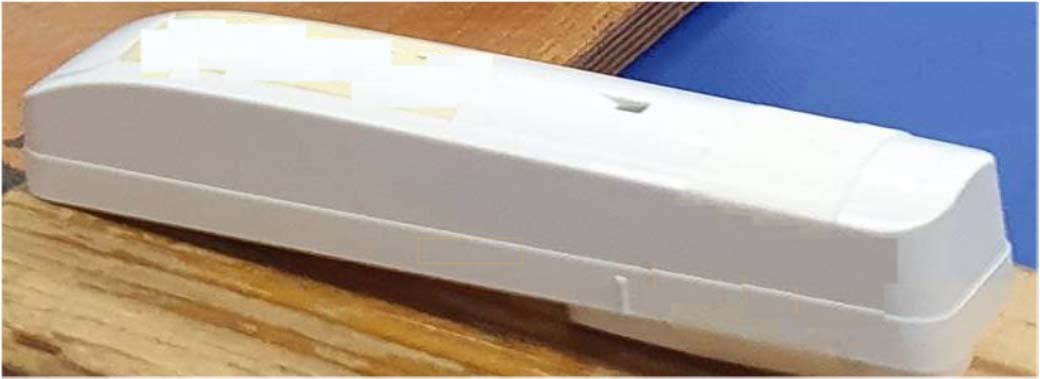
WP3SD304EPG2
Jan 03, 2021PowerG Wireless Shock Detector
Equipment Class
DSS - Part 15 Spread Spectrum Transmitter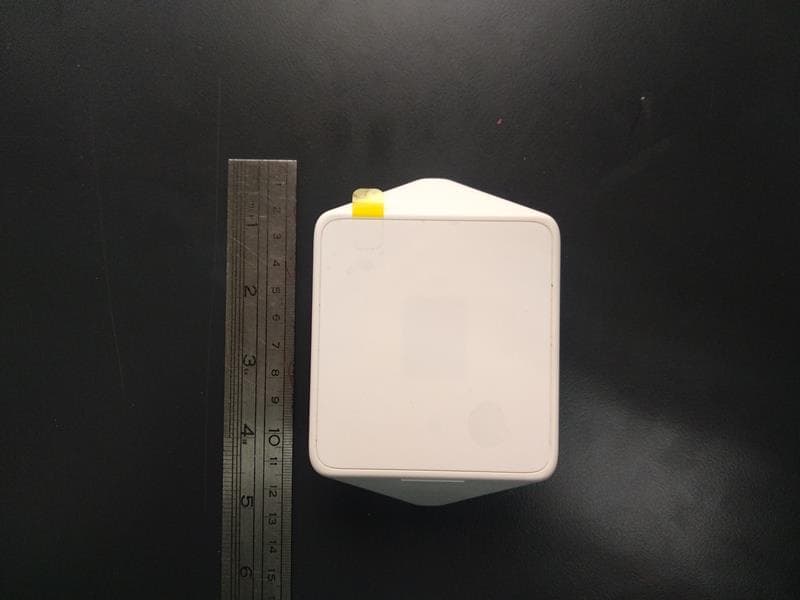
WP3MP843
Jun 30, 2020PIR detector ZigBee
Equipment Class
DTS - Digital Transmission System