X3XVPR-1VP Receiver
TECHNO HORIZON CO.,LTD.
Click to zoom
Application Details
- Equipment Class
- DTS - Digital Transmission System
- Date of Grant
- Feb 28, 2012
- Application Purpose
- Original Equipment
- Date of Application
- Feb 28, 2012
- Equipment Note
- VP Receiver
- Frequency Range
- 5745.00000000 - 5805.00000000
- Company
- TECHNO HORIZON CO.,LTD.
- Country
- Japan
Documents & Files
Document Text
Text extracted from the exhibit documents filed with the FCC. Open a document above to read the original.
Users Manual
■ Heat The product should be situated away from heat sources such as radiators, heat registers, stoves, or other products (including amplifiers) that produce heat. VP Receiver VPR-1 IMPORTANT SAFEGUARDS ■ Read Instructions All the safety and operating instructions should be read before the appliance is operated. ■ Retain Instructions The safety and operating instructions should be retained for future reference. ■ Heed Warnings All warnings on the product and in the operating instructions should be adhered to. ■ Follow Instructions All operating and use instructions should be followed. ■ Cleaning Unplug this product from the wall outlet before cleaning. Do not use liquid cleaners or aerosol cleaners. Use a damp cloth for cleaning. ■ Attachments Do not use attachments not recommended by the product manufacturer as they may cause hazards. ■ Water and Moisture Do not use this product near water - for example, near a bath tub, wash bowl, kitchen sink, or laundry tub, in a wet basement, or near a swimming pool, and the like. ■ Placement Do not place this product on an unstable cart, stand, tripod, bracket, or table. The product may fall, causing serious injury to a child or adult, and serious damage to the product. Use only with a cart, stand, tripod, bracket, or table recommended by the manufacturer, or sold with the product. Any mounting of the product should follow the manufacturer's instructions, and should use a mounting accessory recommended by the manufacturer. ■ Ventilation Slots and openings in the cabinet are provided for ventilation and to ensure reliable operation of the product and to protect it from overheating, and these openings must not be blocked or covered. The openings should never be blocked by placing the product on a bed, sofa, rug, or other similar surface. This product should not be placed in a built-in installation such as a bookcase or rack unless proper ventilation is provided or the manufacturer's instructions have been adhered to. ■ Power Sources This product should be operated only from the type of power source indicated on the marking label. If you are not sure of the type of power supply to your home consult your appliance dealer or local power company. For products intended to operate from battery power, or other sources, refer to the operating instructions. ■ Grounding or Polarization This product may be equipped with either a polarized 2-wire AC line plug (a plug having one blade wider than the other) or a 3-wire grounding type plug, a plug having a third (grounding) pin. The 2-wire polarized plug will fit into the power outlet only one way. This is a safety feature. If you are unable to insert the plug fully into the outlet, try reversing the plug. If the plug still fails to fit, contact your electrician to replace your obsolete outlet. Do not defeat the safety purpose of the polarized plug. The 3-wire grounding type plug will fit into a grounding type power outlet. This is a safety feature. If you are unable to insert the plug into the outlet, contact your electrician to replace your obsolete outlet. Do not defeat the safety purpose of the grounding type plug. ■ Power-Cord Protection Power-supply cords should be routed so that they are not likely to be walked on or pinched by items placed upon or against them, paying particular attention to cords at plugs, convenience receptacles, and the point where they exit from the product. ■ Lightning For added protection for this product during a lightning storm, or when it is left unattended and unused for long periods of time, unplug it from the wall outlet and disconnect the antenna or cable system. This will prevent damage to the product due to lightning and power-line surges. ■ Overloading Do not overload wall outlets, extension cords, or integral convenience receptacles as this can result in a risk of fire or electric shock. ■ A product and cart combination should be moved with care. Quick stops, excessive force, and uneven surfaces may cause the product and cart combination to overturn. ■ Object and Liquid Entry Never push objects of any kind into this product through openings as they may touch dangerous voltage points or short-out parts that could result in a fire or electric shock. Never spill liquid of any kind on the product. ■ Servicing Do not attempt to service this product yourself as opening or removing covers may expose you to dangerous voltage or other hazards. Refer all servicing to qualified service personnel. ■ Damage Requiring Service Unplug this product from the wall outlet and refer servicing to qualified service personnel under the following conditions: -When the power-supply cord or plug is damaged. -If liquid has been spilled, or objects have fallen into the product. -If the product has been exposed to rain or water. -If the product does not operate normally by following the operating instructions. Adjust only those controls that are covered by the operating instructions as an improper adjustment of other controls may result in damage and will often require extensive work by a qualified technician to restore the product to its normal operation. -If the product has been dropped or damaged in any way. -When the product exhibits a distinct change in performance - this indicates a need for service. ■ Replacement Parts When replacement parts are required, be sure the service technician has used replacement parts specified by the manufacturer or have the same characteristics as the original part. Unauthorized substitutions may result in fire, electric shock or other hazards. ■ Safety Check Upon completion of any service or repairs to this product, ask the service technician to perform safety checks to determine that the product is in proper operating condition. WARNING: TO REDUCE THE RISK OF FIRE OR ELECTRIC SHOCK, DO NOT EXPOSE THIS PRODUCT TO RAIN OR MOISTURE. FCC CAUTION: Changes or modifications not expressly approved by the party responsible for compliance could void the user’s authority to o…
Text truncated - open the document above for the full version.
External Photos
Page 1 CONSTRUCTION PHOTOS OF EUT Page 2 Page 3 Page 4
Internal Photos
Page 5 Page 6 Page 7
RF Exposure Info
Report No.: SA111114C06A Report Format Version 4.0.0 Reference No.: 120116C11 1 RF EXPOSURE REPORT REPORT NO.: SA111114C06A MODEL NO.: VPR-1 FCC ID: X3XVPR-1 RECEIVED: Nov. 07, 2011 TESTED: Nov. 07 ~ Nov. 24, 2011 ISSUED: Jan. 31, 2012 APPLICANT: ELMO COMPANY, LIMITED ADDRESS: 6-14, MEIZEN-CHO, MIZUHO-KU NAGOYA, 467-8567, JAPAN ISSUED BY: Bureau Veritas Consumer Products Services (H.K.) Ltd., Taoyuan Branch LAB ADDRESS: No. 47, 14th Ling, Chia Pau Vil., Lin Kou Dist., New Taipei City, Taiwan ( R.O.C ) TEST LOCATION: No. 19, Hwa Ya 2nd Rd, Wen Hwa Tsuen, Kwei Shan Hsiang, Taoyuan Hsien 333, Taiwan, R.O.C. This test report consists of 5 pages in total. It may be duplicated completely for legal use with the approval of the applicant. It should not be reproduced, except in full, without the written approval of our laboratory. The client should not use it to claim product, certification, approval, or endorsement by any government agency. The test results in the report only apply to the tested sample. Report No.: SA111114C06A Report Format Version 4.0.0 Reference No.: 120116C11 2 TABLE OF CONTENTS RELEASE CONTROL RECORD ................................................................................................ 3 1. CERTIFICATION ............................................................................................................. 4 2. RF EXPOSURE............................................................................................................... 5 2.1 LIMITS FOR MAXIMUM PERMISSIBLE EXPOSURE (MPE)......................................... 5 2.2 MPE CALCULATION FORMULA .................................................................................... 5 2.3 CLASSIFICATION ........................................................................................................... 5 2.4 CALCULATION RESULT OF MAXIMUM CONDUCTED POWER.................................. 5 Report No.: SA111114C06A Report Format Version 4.0.0 Reference No.: 120116C11 3 RELEASE CONTROL RECORD ISSUE NO. REASON FOR CHANGE DATE ISSUED Original release NA Jan. 31, 2012 Report No.: SA111114C06A Report Format Version 4.0.0 Reference No.: 120116C11 4 1. CERTIFICATION PRODUCT: VP Receiver MODEL: VPR-1 BRAND: ELMO APPLICANT: ELMO COMPANY, LIMITED TESTED: Nov. 07 ~ Nov. 24, 2011 TEST SAMPLE: ENGINEERING SAMPLE STANDARDS: FCC Part 2 (Section 2.1091) FCC OET Bulletin 65, Supplement C (01-01) IEEE C95.1 The above equipment (Model: VPR-1) has been tested by Bureau Veritas Consumer Products Services (H.K.) Ltd., Taoyuan Branch, and found compliance with the requirement of the above standards. The test record, data evaluation & Equipment Under Test (EUT) configurations represented herein are true and accurate accounts of the measurements of the sample’s EMC characteristics under the conditions specified in this report. PREPARED BY : , DATE:Jan. 31, 2012 Polly Chien / Specialist APPROVED BY : , DATE: Jan. 31, 2012 Gary Chang / Technical Manager Report No.: SA111114C06A Report Format Version 4.0.0 Reference No.: 120116C11 5 2. RF EXPOSURE 2.1 LIMITS FOR MAXIMUM PERMISSIBLE EXPOSURE (MPE) FREQUENCY RANGE (MHz) ELECTRIC FIELD STRENGTH (V/m) MAGNETIC FIELD STRENGTH (A/m) POWER DENSITY (mW/cm 2 ) AVERAGE TIME (minutes) LIMITS FOR GENERAL POPULATION / UNCONTROLLED EXPOSURE 300-1500 ... ... F/1500 30 1500-100,000 ... ... 1.0 30 F = Frequency in MHz 2.2 MPE CALCULATION FORMULA Pd = (Pout*G) / (4*pi*r2) where Pd = power density in mW/cm2 Pout = output power to antenna in mW G = gain of antenna in linear scale Pi = 3.1416 R = distance between observation point and center of the radiator in cm 2.3 CLASSIFICATION The antenna of this product, under normal use condition, is at least 20cm away from the body of the user. So, this device is classified as Mobile Device. 2.4 CALCULATION RESULT OF MAXIMUM CONDUCTED POWER FREQUENCY BAND (MHz) MAX POWER (dBm) ANTENNA GAIN (dBi) DISTANCE (cm) POWER DENSITY (mW/cm 2 ) LIMIT (mW/cm 2 ) 5180-5240 14.1 2 20 0.008 1 5745-5805 21.8 2 20 0.048 1
Test Report
Report No.: RF111114C06A 1 Report Format Version 4.1.0 Reference No.: 120116C11 FCC TEST REPORT (15.247) REPORT NO.: RF111114C06A MODEL NO.: VPR-1 FCC ID: X3XVPR-1 RECEIVED: Nov. 07, 2011 TESTED: Nov. 07 ~ Nov. 24, 2011 ISSUED: Jan. 31, 2012 APPLICANT: ELMO COMPANY, LIMITED ADDRESS: 6-14, MEIZEN-CHO, MIZUHO-KU NAGOYA, 467-8567, JAPAN ISSUED BY: Bureau Veritas Consumer Products Services (H.K.) Ltd., Taoyuan Branch LAB ADDRESS: No. 47, 14th Ling, Chia Pau Vil., Lin Kou Dist., New Taipei City, Taiwan ( R.O.C ) TEST LOCATION: No. 19, Hwa Ya 2nd Rd, Wen Hwa Tsuen, Kwei Shan Hsiang, Taoyuan Hsien 333, Taiwan, R.O.C. This test report consists of 40 pages in total. It may be duplicated completely for legal use with the approval of the applicant. It should not be reproduced except in full, without the written approval of our laboratory. The client should not use it to claim product, certification, approval or endorsement by TAF or any government agency. The test results in the report only apply to the tested sample. Report No.: RF111114C06A 2 Report Format Version 4.1.0 Reference No.: 120116C11 TABLE OF CONTENTS RELEASE CONTROL RECORD.............................................................................................. 4 1. CERTIFICATION........................................................................................................... 5 2. SUMMARY OF TEST RESULTS .................................................................................. 6 2.1 MEASUREMENT UNCERTAINTY................................................................................ 6 3. GENERAL INFORMATION ........................................................................................... 7 3.1 GENERAL DESCRIPTION OF EUT ............................................................................. 7 3.2 DESCRIPTION OF TEST MODES ............................................................................... 9 3.2.1 CONFIGURATION OF SYSTEM UNDER TEST .......................................................... 9 3.2.2 DESCRIPTION OF SUPPORT UNITS ......................................................................... 9 3.2.3 TEST MODE APPLICABILITY AND TESTED CHANNEL DETAIL ............................. 10 3.3 GENERAL DESCRIPTION OF APPLIED STANDARDS ............................................ 12 4. TEST TYPES AND RESULTS .................................................................................... 13 4.1 RADIATED EMISSION AND BANDEDGE MEASUREMENT..................................... 13 4.1.1 LIMITS OF RADIATED EMISSION AND BANDEDGE MEASUREMENT .................. 13 4.1.2 TEST INSTRUMENTS................................................................................................ 14 4.1.3 TEST PROCEDURES ................................................................................................ 15 4.1.4 DEVIATION FROM TEST STANDARD....................................................................... 15 4.1.5 TEST SETUP.............................................................................................................. 16 4.1.6 EUT OPERATING CONDITIONS ............................................................................... 16 4.1.7 TEST RESULTS ......................................................................................................... 17 4.2 CONDUCTED EMISSION MEASUREMENT ............................................................. 23 4.2.1 LIMITS OF CONDUCTED EMISSION MEASUREMENT........................................... 23 4.2.2 T EST INSTRUMENTS............................................................................................... 23 4.2.3 TEST PROCEDURES ................................................................................................ 24 4.2.4 DEVIATION FROM TEST STANDARD....................................................................... 24 4.2.5 TEST SETUP.............................................................................................................. 25 4.2.6 EUT OPERATING CONDITIONS ............................................................................... 25 4.2.7 TEST RESULTS ......................................................................................................... 26 4.3 6dB BANDWIDTH MEASUREMENT.......................................................................... 28 4.3.1 LIMITS OF 6dB BANDWIDTH MEASUREMENT ....................................................... 28 4.3.2 TEST SETUP.............................................................................................................. 28 4.3.3 TEST INSTRUMENTS................................................................................................ 28 4.3.4 TEST PROCEDURE................................................................................................... 28 4.3.5 DEVIATION FROM TEST STANDARD....................................................................... 28 4.3.6 EUT OPERATING CONDITIONS ............................................................................... 28 Report No.: RF111114C06A 3 Report Format Version 4.1.0 Reference No.: 120116C11 4.3.7 TEST RESULTS ......................................................................................................... 29 4.4 CONDUCTED OUTPUT POWER............................................................................... 30 4.4.1 LIMITS OF MAXIMUM OUTPUT POWER MEASUREMENT..................................... 30 4.4.2 TEST SETUP.............................................................................................................. 30 4.4.3 INSTRUMENTS .......................................................................................................... 30 4.4.4 TEST PROCEDURES ................................................................................................ 30 4.4.5 DEVIATION FROM TEST STANDARD....................................................................... 30 4.4.6 EUT OPERATING CONDITIONS ....................…
Text truncated - open the document above for the full version.
Test Report
Report No.: RF111114C06A-1 1 Report Format Version 4.1.0 Reference No.: 120116C11 FCC TEST REPORT (15.407) REPORT NO.: RF111114C06A-1 MODEL NO.: VPR-1 FCC ID: X3XVPR-1 RECEIVED: Nov. 07, 2011 TESTED: Nov. 07 ~ Nov. 24, 2011 ISSUED: Jan. 31, 2012 APPLICANT: ELMO COMPANY, LIMITED ADDRESS: 6-14, MEIZEN-CHO, MIZUHO-KU NAGOYA, 467-8567, JAPAN ISSUED BY: Bureau Veritas Consumer Products Services (H.K.) Ltd., Taoyuan Branch LAB ADDRESS: No. 47, 14th Ling, Chia Pau Vil., Lin Kou Dist., New Taipei City, Taiwan ( R.O.C ) TEST LOCATION: No. 19, Hwa Ya 2nd Rd, Wen Hwa Tsuen, Kwei Shan Hsiang, Taoyuan Hsien 333, Taiwan, R.O.C. This test report consists of 42 pages in total. It may be duplicated completely for legal use with the approval of the applicant. It should not be reproduced except in full, without the written approval of our laboratory. The client should not use it to claim product, certification, approval or endorsement by TAF or any government agency. The test results in the report only apply to the tested sample. Report No.: RF111114C06A-1 2 Report Format Version 4.1.0 Reference No.: 120116C11 TABLE OF CONTENTS RELEASE CONTROL RECORD.......................................................................................... 4 1. CERTIFICATION ...................................................................................................... 5 2. SUMMARY OF TEST RESULTS .............................................................................. 6 2.1 MEASUREMENT UNCERTAINTY ........................................................................... 6 3. GENERAL INFORMATION....................................................................................... 7 3.1 GENERAL DESCRIPTION OF EUT......................................................................... 7 3.2 DESCRIPTION OF TEST MODES........................................................................... 8 3.2.1 CONFIGURATION OF SYSTEM UNDER TEST ...................................................... 9 3.2.2 DESCRIPTION OF SUPPORT UNITS ..................................................................... 9 3.2.3 TEST MODE APPLICABILITY AND TESTED CHANNEL DETAIL ......................... 10 3.3 GENERAL DESCRIPTION OF APPLIED STANDARDS ........................................ 11 4. TEST TYPES AND RESULTS ................................................................................ 12 4.1 RADIATED EMISSION AND BANDEDGE MEASUREMENT................................. 12 4.1.1 LIMITS OF RADIATED EMISSION AND BANDEDGE MEASUREMENT .............. 12 4.1.2 LIMITS OF UNWANTED EMISSION OUT OF THE RESTRICTED BANDS .......... 12 4.1.3 TEST INSTRUMENTS ........................................................................................... 13 4.1.4 TEST PROCEDURES ............................................................................................ 14 4.1.5 DEVIATION FROM TEST STANDARD .................................................................. 14 4.1.6 TEST SETUP ......................................................................................................... 15 4.1.7 EUT OPERATING CONDITION ............................................................................. 15 4.1.8 TEST RESULTS ..................................................................................................... 16 4.2 CONDUCTED EMISSION MEASUREMENT ......................................................... 22 4.2.1 LIMITS OF CONDUCTED EMISSION MEASUREMENT....................................... 22 4.2.2 TEST INSTRUMENTS ........................................................................................... 22 4.2.3 TEST PROCEDURES ............................................................................................ 23 4.2.4 DEVIATION FROM TEST STANDARD .................................................................. 23 4.2.5 TEST SETUP ......................................................................................................... 24 4.2.6 EUT OPERATING CONDITIONS ........................................................................... 24 4.2.7 TEST RESULTS ..................................................................................................... 25 4.3 MAXIMUM CONDUCTED OUTPUT POWER MEASUREMENT ........................... 27 4.3.1 LIMITS OF MAXIMUM CONDUCTED OUTPUT POWER MEASUREMENT ........ 27 4.3.2 TEST SETUP ......................................................................................................... 27 4.3.3 TEST INSTRUMENTS ........................................................................................... 27 4.3.4 TEST PROCEDURE .............................................................................................. 28 4.3.5 DEVIATION FROM TEST STANDARD .................................................................. 28 4.3.6 EUT OPERATING CONDITIONS ........................................................................... 28 4.3.7 TEST RESULTS ..................................................................................................... 29 4.4 PEAK POWER EXCURSION MEASUREMENT .................................................... 30 4.4.1 LIMITS OF PEAK POWER EXCURSION MEASUREMENT.................................. 30 Report No.: RF111114C06A-1 3 Report Format Version 4.1.0 Reference No.: 120116C11 4.4.2 TEST SETUP ......................................................................................................... 30 4.4.3 TEST INSTRUMENTS ........................................................................................... 30 4.4.4 TEST PROCEDURE .............................................................................................. 30 4.4.5 DEVIATION FROM TEST STANDARD .................................................................. 30 4.4.6 EUT OPERATING CONDITIONS ........................................................................... 30 4.4.7 TEST RESULTS ...........................................................................…
Text truncated - open the document above for the full version.
Test Setup Photos
1 PHOTOGRAPHS OF THE TEST CONFIGURATION CONDUCTED EMISSION TEST 2 RADIATED EMISSION TEST
Contact Information
Applicant
Hidehito Achiwa(Section Manager)
Technical Contact
Bureau Veritas CPS (H.K.) Ltd. Taoyuan BranchGary Chang
[email protected]886-3-3183232
No. 19, Hwa Ya 2nd Rd., Kwei Shan Hsiang · Taoyuan Hsien · Taiwan
Non-Technical Contact
Bureau Veritas CPS (H.K.) Ltd. Taoyuan BranchNatacha Chen
[email protected]886-3-3183232
Test Firm
Bureau Veritas CPS (H.K.) Ltd. Taoyuan BranchRichard Chen
Technical Specifications
| # | Rule Parts | Frequency Range | Power Output |
|---|---|---|---|
| 1 | 15C | 5.75 GHz - 5.80 GHz | 151.00 mW |
Other Applications from TECHNO HORIZON CO.,LTD.

X3XMX-P3W
Aug 30, 2023DOCUMENT CAMERA
Equipment Class
DTS - Digital Transmission System
X3XRC-VLCE
Nov 03, 2020HS-2remote control
Equipment Class
DTS - Digital Transmission System
X3X-CRA-2
Jan 18, 2020Wireless PenTablet
Equipment Class
DXX - Part 15 Low Power Communication Device Transmitter
X3XMS-1
Mar 09, 2014Free Style CAMERA QBiC
Equipment Class
DTS - Digital Transmission System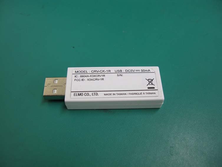
X3XCRV-1R
Feb 24, 2012USB Dongle
Equipment Class
JBP - Part 15 Class B Computing Device Peripheral