X59-BA-100Bluetooth Adapter
H3 SYSTEM Co., Ltd.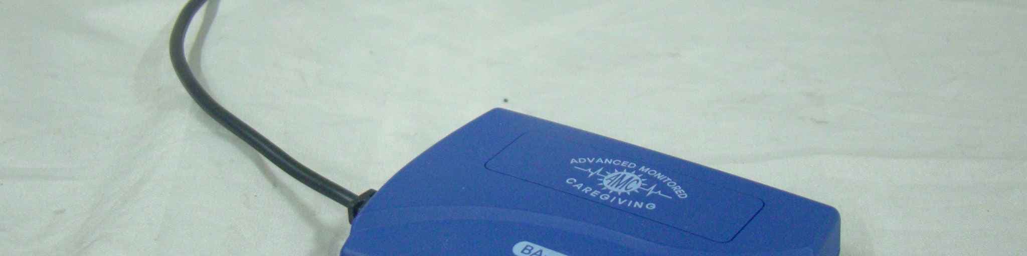
Click to zoom
Application Details
- Equipment Class
- DSS - Part 15 Spread Spectrum Transmitter
- Date of Grant
- Feb 18, 2010
- Application Purpose
- Original Equipment
- Date of Application
- Feb 18, 2010
- Equipment Note
- Bluetooth Adapter
- Frequency Range
- 2402.00000000 - 2480.00000000
- Company
- H3 SYSTEM Co., Ltd.
- Country
- South Korea
Documents & Files
Document Text
Text extracted from the exhibit documents filed with the FCC. Open a document above to read the original.
Users Manual
User’s Manual Bluetooth Adapter (Bluetooth adapter for a glucometer) BA-100 2 USA-Federal Communications Commission (FCC) This device complies with part 15 of the FCC Rules. Operation is subject to the following two conditions: (1) This device may not cause harmful interference, and (2) this device must accept any interference received, including interference that may cause undesired operation. This equipment has been tested and found to comply with the limits for a Class B digital device, pursuant to Part 15 of FCC Rules. These limits are designed to provide reasonable protection against harmful interference in a residential installation. This equipment generates, uses, and can radiate radio frequency energy. If not installed and used in accordance with the instructions, it may cause harmful interference to radio communications. However, there is no guarantee that interference will not occur in a particular installation. If this equipment does cause harmful interference to radio or television reception, which can be determined by tuning the equipment off and on, the user is encouraged to try and correct the interference by one or more of the following measures: - Reorient or relocate the receiving antenna - Increase the distance between the equipment and the receiver. - Connect the equipment to outlet on a circuit different from that to which the receiver is connected. - Consult the dealer or an experienced radio/TV technician for help. Any changes or modifications not expressly approved by the party responsible for compliance could void the user’s authority to operate the equipment. Caution: Exposure to Radio Frequency Radiation. 1. This device and its antenna must not be co-located or operating in conjunction with any other antenna or transmitter. To maintain compliance with FCC RF exposure guidelines for bodyworn operation, do not use accessories that contain metallic components. 2. This equipment complies with FCC RF radiation exposure limits set forth for an uncontrolled environment. This equipment should be installed and operated with a minimum distance of 20 centimeters between the radiator and your body. 3 Welcome l Thank you for purchasing Bluetooth adapter (BA-100). l The Bluetooth adapter is a data transmitter that receives data from a glucometer and sends the data to other devices such as a mobile phone, a gateway, etc. via Bluetooth. l The Bluetooth adapter can be connected to Johnson and Johnson’s One Touch Ultra, One Touch Ultra 2, and One Touch Mini. l The Bluetooth adapter can send data to MobiCliniQ software made by Aerotel on Nokia 2720 mobile phone or compatible devices. Packaging List l Bluetooth adapter (BA-100) l User’s manual 4 Descriptions ① Body ② Cable ③ Connector: Connector to a glucometer ④ Button: A button used for Bluetooth pairing and manual transmission ⑤ LED: 2-color(Green and Red) LED ⑥ Dry cell cover: Cover below which dry cells are put 5 ⑦ Label 6 How to Use 1. [Preparation] l Insert batteries. Open the cell cover to place AAA 1.5V 2 EA while checking the polarity (+,- ) and then close the cover. l Connect the cable to a glucometer l The Bluetooth adapter is usually provided with a compatible glucometer and a Nokia 2720 mobile phone with MobiCliniQ software. If you are not provided with the glucometer or the mobile phone, please contact the service provider or customer service. 2. [Data transfer] l Measure blood glucose while the adapter is being connected to a glucometer. l The measured data is automatically transmitted to the pre-determined device such as a mobile phone, a gateway, etc. 3. [Bluetooth pairing] 7 l Bluetooth pairing with Nokia 2720. l [BA-100] Press the button for more than 3 seconds. l [BA-100] Confirm that the red LED is ON. l [Nokia 2720] Go to “Bluetooth menu → Paired devices.” Select “Add new device” for searching for the Bluetooth adapter. l [Nokia 2720] Find a device name, “AMC_JandJ” l [Nokia 2720] “Add” AMC_JandJ for pairing. l [Nokia 2710] Input “1234” for the passcode. l [BA-100] After a while, the green LED turns ON. l [BA-100] After a while, the red LED turns ON. l [BA-100] And then, the green and red LEDs turn OFF. l [Nokia 2720] Run MobiCliniQ software l [BA-100] Connect a glucometer to the Bluetooth adapter and press the button for test. l [Glucometer] “PC” is shown. l [BA-100] The red LED blinks twice. The green LED blinks for a while. And then, the red and green LEDs turn OFF. l [Nokia 2720] See the messages on MobiCliniQ software 4. [Manual data transmission] l Press the button of the Bluetooth adapter while a glcuometer and the adapter are being connected. The whole readings stored in the glucometer will be automatically downloaded into the Nokia 2720 and be shown in MobiCliniQ software. 8 Troubleshooting l If you have some troubles in data transmission, please check the below l Try to do “Manual transmission” by pressing the button while a glcuometer and the adapter are being connected. l Replace batteries with new ones. l Try to do Bluetooth pairing. 9 Cautions l Be sure to carefully read the user’s manual before use. l Only one glucometer of a certain patient should be used for one Bluetooth adapter. If you should change the glucometer, then first do manual transmission by pressing the button, change the glucomter, and do manual transmission once more. l Keep connections between the Bluetooth adapter and the glucometer. l After Bluetooth pairing, do manual transmission. l Keep it in a clean and dry place away from dust or corrosive gases as well as away from fires. l Keep it away from moisture. l Do not apply any shock or vibration to the product. l Do not rub the product with inflammables such as alcohol, benzene, or acetone that can cause chemical change. Use a dry cloth to prevent the surface from being damaged. l Disassembling the product is not advisable. 10 Specification l Function: it automatically receives blood glucose data measured from a glucometer and transmits to a pre-determined device via Bluetoo…
Text truncated - open the document above for the full version.
Cover Letter(s)
FCC ID:X59-BA-100 Attestation Statment H3 SYSTEM Co., Ltd. FCC ID:X59-BA-100 Date: February 1, 2010 15.247(a)(1) The hopping sequence must be pseudorandom all channels are used eually on average The receiver input bandwidth is approximately equall to the transmit bandwidth The receiver hops in sequence with the transmitted signal. 15.247(g) The system is designed to comply with all of the regulations in Section 15.247 When the transmitter is presented with a continuous data (or information) 15.247(h) The system does not coordinate its channel selection/hopping sequence with other Frequency hopping systems for the express purpose of avoiding the simultaneous Occupancy of individual hopping frequencies by multiple transmitters. Sincerely Jin Mo Yang, Engineering manager [email protected] TEL:82-31-631-8037 FAX:82-31-631-8039
External Photos
1. FRONT 2. REAR 3. PORT
ID Label/Location Info
1.Product Name : Bluetooth Adapter (BA-100) 2.Manufacturer : H3 SYSTEM Co., Ltd. FCC : X59-BA-100 This device complies with part 15 the FCC RulesMade in Korea ** Label
Internal Photos
INTERNAL PHOTO 1. MAIN 1.1 Front 1.2 Rear
Operational Description
7 [Bluetooth pairing] l Bluetooth pairing with Nokia 2720. l [BA-100] Press the button for more than 3 seconds. l [BA-100] Confirm that the red LED is ON. l [Nokia 2720] Go to “Bluetooth menu → Paired devices.” Select “Add new device” for searching for the Bluetooth adapter. l [Nokia 2720] Find a device name, “AMC_JandJ” l [Nokia 2720] “Add” AMC_JandJ for pairing. l [Nokia 2710] Input “1234” for the passcode. l [BA-100] After a while, the green LED turns ON. l [BA-100] After a while, the red LED turns ON. l [BA-100] And then, the green and red LEDs turn OFF. l [Nokia 2720] Run MobiCliniQ software l [BA-100] Connect a glucometer to the Bluetooth adapter and press the button for test. l [Glucometer] “PC” is shown. l [BA-100] The red LED blinks twice. The green LED blinks for a while. And then, the red and green LEDs turn OFF. l [Nokia 2720] See the messages on MobiCliniQ software 8 [Manual data transmission] l Press the button of the Bluetooth adapter while a glcuometer and the adapter are being connected. The whole readings stored in the glucometer will be automatically downloaded into the Nokia 2720 and be shown in MobiCliniQ software.
Operational Description
HBM2X1M Bluetooth V1.2 Class 2 Module Data Book www.hanamicron.co.kr Rev1.1 May. 2006 Bluetooth Module HBM2X1M Data Book HBM2X1M Bluetooth V1.2 Class 2 Module Data Book www.hanamicron.co.kr 2 page / 18 pages List of contents 1 General 1.1 Overview 1.2 Features 1.3 Application 1.4 Pin Configuration & Outline 1.5 Device Terminal Functions 1.6 Package Dimensions 1.7 Land Pattern Recommendation 2 Characteristics 2.1 Electrical Characteristics 2.2 Radio Characteristics 3 Terminal Descriptions 3.1 UART 3.1.1 UART Setting 3.1.2 UART Bypass Mode 3.2 USB 3.3 SPI 3.4 Kalimba DSP 3.5 Audio Interface 3.6 Stereo Audio Interface 3.7 PCM CODEC Interface 3.7.1 PCM Configuration 3.8 Microphone Input 4 Application Schematic HBM2X1M Bluetooth V1.2 Class 2 Module Data Book www.hanamicron.co.kr 3 page / 18 pages 1. General 1.1 Overview This specification covers Bluetooth module (class-2) which complies with Bluetooth specification version 1.2 and integrates RF & Baseband controller in small package. This Module has deployed CSR’s BC03-Multimedia External chipset. All detailed specification including pinouts and electrical specification may be changed without notice. BC03-MM 8Mb Flash HBM2X1M 3.3V PCM USB UART PIO I2C SPI XTAL 26MHz HBM2X1M Bluetooth V1.2 Class 2 Module Data Book www.hanamicron.co.kr 4 page / 18 pages 1.2 Features Fully Qualified Bluetooth System Bluetooth 1.2 Specification Compliant Kalimba DSP Open Platform Co-Processor Full Speed Bluetooth Operation with Full Piconet Support Operating Voltage 2.7~3.6V UART Interface With programmable baud rate up to 1.5Mbaud with an optional bypass mode Full Speed USB v1.1 Interface Supports OHCI And UHCI Host Interfaces 16-bit Resolution Stereo Audio Codec, Standard Sample Rates of 8kHz, 11.025kHz, 16kHz, 2.05kHz, 32kHz, 44.1kHz And 48kHz (DAC Only) Integrated Amplifiers For Driving Microphone And Speakers With Minimum External Components Standard HCI (UART and USB) support Fully Embedded RFCOMM External 8Mbit Flash Memory Integrated 26MHz Reference Clock Competitive Size (9.0mm x 10.0mm x 1.6mm : LGA 44Pin) 1.3 Application Stereo Headphones Automotive Hands-Free Kits Echo Cancellation High Performance Telephony Headsets A/V Profile Support Cellular Handsets HBM2X1M Bluetooth V1.2 Class 2 Module Data Book www.hanamicron.co.kr 5 page / 18 pages 1.4 Pin Configuration & Outline HBM2X1M Pin Configuration HBM2X1M Outline 1213 14 152019 1817162221 23 24 25 26 27 28 29 30 31 32 33 3435 38 37 3640 39 41 4243 44 1 2 3 6 4 5 7 8 9 10 11 ANTGNDAIN_N_RIGHTAIN_P_RIGHTAIN_N_LEFTAIN_P_LEFTGND AOUT_N_RIGHTAOUT_P_RIGHT AOUT_N_LEFTAOUT_P_LEFT GND GND AIO0 AIO3 PIO7 PCM_SYNC PCM_IN UART_RXD UART_TXD UART_CTS VCC UART _RTSUSB_DPUSB_DN PCM_CLK PIO4PCM_OUTPIO6 PIO5RESETSPI_CLK SPI_MISO SPI_MOSI SPI_CSB PIO8 PIO9 PIO10 PIO11 PIO3 PIO2 PIO1 PIO0 GND HBM2X1M XXXX 10.0 9.0 HBM2X1M Bluetooth V1.2 Class 2 Module Data Book www.hanamicron.co.kr 6 page / 18 pages 1.5 Device Terminal Functions Function Pin Name Pin No. Description PCM_OUT 39 Synchronous data output PCM_IN 29 Synchronous data input PCM_CLK 37 Synchronous data clock PCM Interface PCM_SYNC 28 Synchronous data sync UART_TXD 31 UART data output UART_RXD 30 UART data input (idle status high) UART_RTS 34 UART request to send, active low UART Interface UART_CTS 32 UART clear to send, active low SPI_CSB 2 Chip select for Synchronous Serial Interface Active low SPI_CLK 43 Serial Peripheral Interface clock SPI_MISO 44 Serial Peripheral Interface data output SPI Interface SPI_MOSI 1 Serial Peripheral Interface data input USB_DN 36 USB data minus USB Interface USB_DP 35 USB plus with selectable internal 1.5K pull-up resistor PIO0 10 Programmable input/output line PIO1 9 Programmable input/output line PIO2 8 Programmable input/output line PIO3 7 Programmable input/output line PIO4 38 UART Bypass(UART_TX) PIO5 41 UART Bypass(UART_RTS) PIO6 40 UART Bypass(UART_CTS) / E2PROM(SCL) PIO7 27 UART Bypass(UART_RX) / E2PROM(SDA) PIO8 3 E2PROM (write protect) PIO9 4 Programmable input/output line PIO10 5 Programmable input/output line PIO Interface PIO11 6 Programmable input/output line HBM2X1M Bluetooth V1.2 Class 2 Module Data Book www.hanamicron.co.kr 7 page / 18 pages AUDIO IN_N_RIGHT 12 Microphone input negative(right side) AUDIO IN_P_RIGHT 13 Microphone input positive(right side) AUDIO IN_N_LEFT 16 Microphone input negative (left side) AUDIO IN_P_LEFT 17 Microphone input positive (left side) AUDIO OUT_N_RIGHT19 Speaker output negative (right side) AUDIO OUT_P_RIGHT20 Speaker output positive (right side) AUDIO OUT_N_LEFT 21 Speaker output negative (left side) AUDIO Interface AUDIO OUT_P_LEFT 22 Speaker output positive (left side) AIO0 24 General purpose analogue interface AIO3 25 General purpose analogue interface RESET 42 Reset if hig. Input debounced so must be high for >5ms to cause a reset ANT 15 RF Connection to Antenna VCC 33 D.C Input voltage for operation (2.7~3.6V) Others GND 11, 14, 18, 23, 26Ground HBM2X1M Bluetooth V1.2 Class 2 Module Data Book www.hanamicron.co.kr 8 page / 18 pages 1.6 Package Dimensions 0.5 1.6 10.0 9.0 Ground 2.5 2.5 4.0 3.5 4.5 5.0 2.5 2.5 HBM2X1M Bluetooth V1.2 Class 2 Module Data Book www.hanamicron.co.kr 9 page / 18 pages 1.7 Land Pattern Recommendation HBM2X1M Bluetooth V1.2 Class 2 Module Data Book www.hanamicron.co.kr 10 page / 18 pages 2 Characteristics 2.1 Electrical Characteristics 2.2 Power Consumption Operation Mode Connection Type UART Rate (Kbits/s) Average Unit Inquiring mode -- 115.2 40 mA ACL data transfer no traffic Master 115.2 7 mA ACL data transfer with file transfer Master 115.2 14 mA SCO connection HV1 Master 18 mA Standby Host connection -- 0.02 mA Absolute Maximum Ratings Rating Minimum Maximum Storage temperature -40°C 85°C Supply voltage : VCC -0.4V 3.6V Other terminal voltages VSS -0.4 VCC +0.4V Recommended Operating Conditions Operating Conditions Minimum Maximum Operating temperature range -30°C 80°C Supply voltage : VCC 2.7V 3.6V HBM2X1M …
Text truncated - open the document above for the full version.
RF Exposure Info
RF Exposure Measurement 1. Introduction The maximum Gain measured in Fully Anechoic Chamber is 3.5 dBi or 2.239 (numeric). 2. Classification MODE: GFSK(FHSS) 3. RF Exposure Limit Magnetic Field Strength(A/m) Power Density (mW/cm 2 ) Average Time (minutes) 1.63 * (100) 6 4.89/f * (900/f 2 ) 6 0.1631.06 -f/3006 -56 Magnetic Field Strength(A/m) Power Density (mW/cm 2 ) Average Time (minutes) 1.63 * (100) 30 2.19/f * (180/f 2 ) 30 0.0730.230 -F/150030 -1.030 F = Frequency in MHz * = Plane-wave equivalent power density 1500 - 100,000- 1.34 - 30824/f 30 - 300 300 - 1500 3.0 - 301842/f Frequency Range (MHz) Electric Field Strength (V/m) 30 - 300 - - 1500 - 100,000 LIMITS FOR MAXIMUM PERMISSIBLE EXPOSURE (MPE) (A) Limits for Occupational/Controlled Exposures Frequency Range (MHz) Electric Field Strength (V/m) 0.3 - 1.34614 61.4 (B) Limits for General Population/Uncontrolled Exposure Because this deivce is transmitting the high power signal, it is regarded specially as a dangerous band for its heating harmfulness to the human body. The manufacturer whose product is working in this frequency band is obligatory to prove the harmfulness of his product. In this document, we try to prove the safety of radiation harmfulness to the human body for our product. The limit for Maximum Permissible Exposure (MPE) specified in FCC 1.1310 is followed. The Gain of the antenna used in this product is measured in a Fully Anechoic Chamber (FAC), and the maximum total power input to the antenna is measured. Through the Friis transmission formula and the maximum gain of the antenna, we can calculate the distance, away from the product, where the limit of MPE is reached. Page 1 of 3 The antenna of the product, under normal use condition, is at least 20cm away from the body of the user. Warning statement for keeping 20cm separation distance and the prohibition of operating next to a person has been printed on the user's manual. So, this product is classified as the Mobile Device. According to FCC 1.1310: The criteria listed in the following table shall be used to evaluate the environmental impact of human exposure to radio-frequency(RF) radiation as specified in 1.1307(b). LIMITS FOR MAXIMUM PERMISSIBLE EXPOSURE (MPE) - Class A 300 - 1500 27.5 - 0.3 - 3.0614 4. Friis Formula Friis transmission formula : P d = (P out *G) / (4*π*r 2 ) The maximum Gain measured in Fully Anechoic Chamber is 3.5 dBi or 2.239 (numeric). P out = output power to antenna in mW G = gain of antenna in linear scale Pi = 3.1416 MODE: GFSK Page 2 of 3 The software provided by Manufacturer enabled the EUT to transmit with max power at lowest, middle and highest channel individually. Pd is the limit of MPE, 1mW/cm 2 . If we know the maximum Gain of the antenna and the total power input to the antenna, through the calculation, we will know the distance r where the MPE limit is reached. 5. Test Results 5.1 Antenna Gain The maximum Gain measured in Fully Anechoic Chamber is 3.5 dBi or 2.239 (numeric). 5.2 Output Power into Antenna & RF Exposure value at distance 20cm: MODE: GFSK Channel Channel Frequency (MHz) Output Power to Antenna (mW) Power Density (mW/cm 2 ) Limit of Power Density (mW/cm 2 ) 02402.000.4040.0001801.0 392441.000.4930.0002201.0 782480.000.4210.0001871.0 Page 3 of 3 The minimum allowable distance is very close to the enclosure of the antenna and is very far away from the human beign under normal use condition.
Test Report
Test Report for FCC Company name Address Telephone Product name Model No. Serial No. Test date Testing location Standard Tested by Reviewed by Abbreviation * Note - This test report is not permitted to copy partly without our permission - This test result is dependent on only equipment to be used - This test result based on a single evaluation of one sample of the above mentioned Report Number : ESTF151001-005 , Web : www. estech. co. kr Page 1 of 39 Report NumberESTF151001-005 Manufacturer Country of origin Applicant Product NONE H3 SYSTEM Co., Ltd. KOREA FCC ID:X59-BA-100 OK, Pass = Passed, Fail = Failed, N/A = not applicable Engineer H.H.Lee Engineering Manager J.M.Yang (Signature) (Signature) 26-Jan-10 H3 SYSTEM Co., Ltd. 3F,397-27,Doryong-dong,Yuseong-gu,Daejeon 82-42-862-9314 Measurement facility registration number 94696 ESTECH. Co., Ltd. 97-1 Hoiuk-Ri Majang-Myon, Icheon-city, KyungKi-Do, Korea FCC PART 15 2008 , ANSI C 63.4 2003 2009-12-29 ~2010-1-25 Bluetooth Adapter BA-100 Date of issue EST-QP-20-01(0)-(F15) 4 5 6 7 10 10 10 10 11 13 13 13 14 14 14 14 15 16 16 16 16 16 5. Carrier Frequency Separation ................................................................................. 5.2 Test instruments and measurement setup ............................................................ 5.3 Measurement results .......................................................................................... Contents 1 1. Laboratory Information ............................................................................................................ 2. Description of EUT ................................................................................................ 3. Test Standards ...................................................................................................... 4. Measurement condition .......................................................................................... 8.2 Test instruments and measurement setup ............................................................ 8.4 Trace Data ...................................................................................................... 5.1 Test procedure ................................................................................................ 6.1 Test procedure ................................................................................................ 6.2 Measurement results ............................................................ 5.4 Trace data ...................................................................................................... 6. Maximum Peak Output Power ................................................................................. 7.3 Measurement results ....................................................................................... Report Number : ESTF151001-005 , Web : www. estech. co. kr Page 2 of 39 7. Number of Hopping Frequency .................................................................................... 7.1 Test procedure ................................................................................................ 7.2Test instruments and measurement setup ....................................................................................... 7.4 Trace data ....................................................................................... 8. Time of Occupancy (Dwell Time) ........................................................................... 8.1 Test procedure ................................................................................................ 8.3 Measurement results ....................................................................................... EST-QP-20-01(0)-(F15) 19 19 19 19 20 25 25 25 26 30 34 11.1 Measurement equipment ........................................................................34 11.2 Environmental conditions ........................................................................34 35 36 36 37 38 39 9.4 Trace data of band-edge & out of emission ...................................................................................................... 10. Measurement of radiated emission ........................................................................... Appendix 1. Antenna Requirement 11. Measurement of conducted emission ........................................................................ 11.3 Test data ......................................................................................................... 12.2. Setup for Radiated Test :Above 1000 MHz .................................................................................... 12.3. Setup for Conducted Test : 0.15 ~ 30 MHz ......................................................................................................... Report Number : ESTF151001-005 , Web : www. estech. co. kr Page 3 of 39 10.1 Measurement equipment .................................................................................... 10.2 Environmental conditions .................................................................................... Contents 2 12.4. Photographs of EUT.......................................................................................... 10.3 Test data(bluetooth) ......................................................................................................... 10.4 Restricted Band Edges ......................................................................................................... 12. Photographs of test setup ........................................................................... 12.1.Setup for Radiated Test : 30 ~ 1000 MHz .................................................................................... 9.2 Test instruments and measurement setup ............................................................ 9.3 Measurement results of band-edge & out of emission ....................................................................................... 9. Band-edge and Out of band emissions ...........…
Text truncated - open the document above for the full version.
Test Setup Photos
TEST SETUP PHOTO 1. Radiated Emission setup photo 1.1. Front 1.2. Rear 1.3. Front (Above 1000MHz)
Contact Information
Applicant
Sung-Dae Lim(Director)
Test Firm
ESTECH Co., Ltd.Yang Jinmo
Technical Specifications
| # | Rule Parts | Frequency Range | Power Output |
|---|---|---|---|
| 1 | 15C | 2.40 GHz - 2.48 GHz | 500.00 µW |
Other Applications from H3 SYSTEM Co., Ltd.
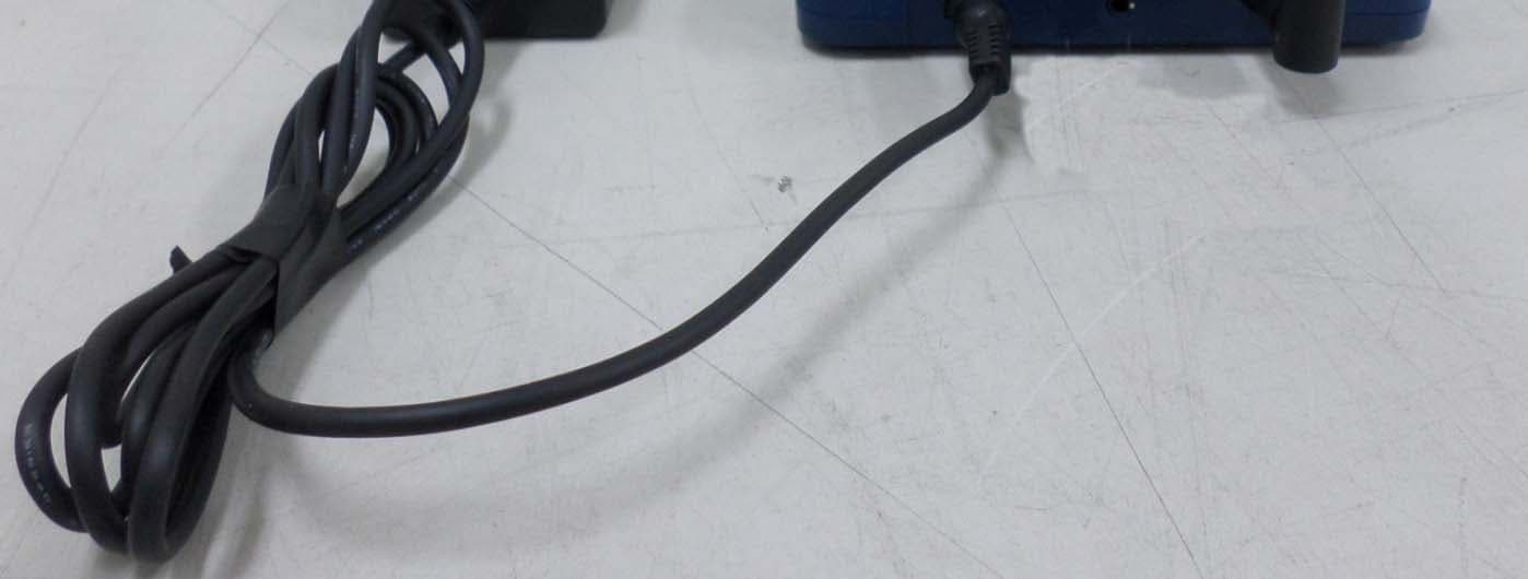
X59-H3G-800
May 18, 2015CDMA Gateway
Equipment Class
DSS - Part 15 Spread Spectrum Transmitter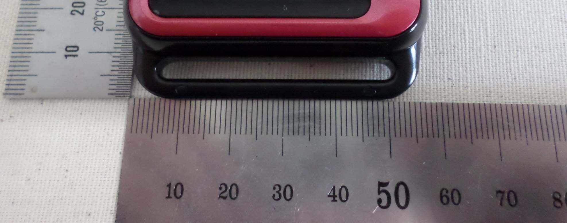
X59-HRM-3200
Mar 23, 2015Heart Rate Monitor
Equipment Class
DTS - Digital Transmission System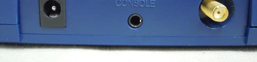
X59-H3G-650
Apr 15, 2012CDMA Gateway
Equipment Class
DSS - Part 15 Spread Spectrum Transmitter
X59-HRM-1000
Mar 19, 2012Heart Rate Monitor
Equipment Class
DTS - Digital Transmission System
X59-BA-110
Dec 19, 2011Bluetooth Adapter
Equipment Class
DSS - Part 15 Spread Spectrum Transmitter