X59-HRM-3200Heart Rate Monitor
H3 SYSTEM Co., Ltd.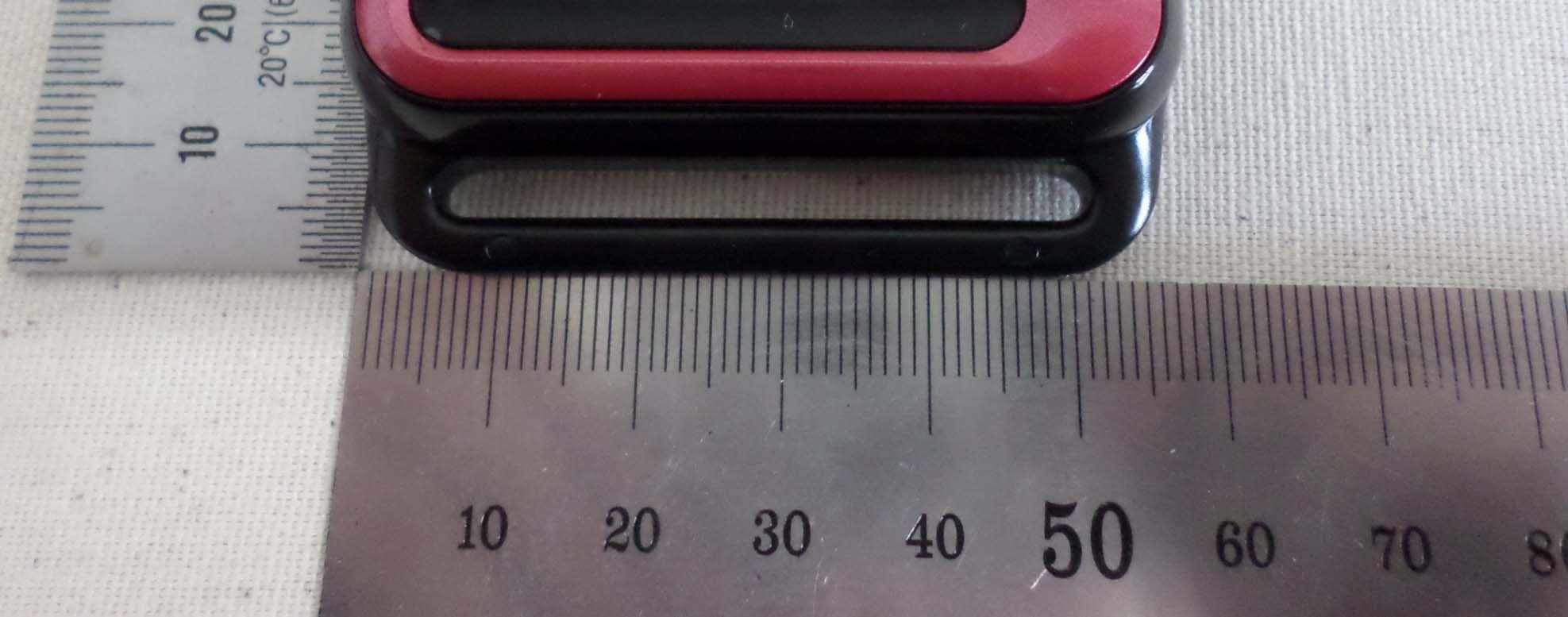
Click to zoom
Application Details
- Equipment Class
- DTS - Digital Transmission System
- Date of Grant
- Mar 23, 2015
- Application Purpose
- Original Equipment
- Date of Application
- Mar 23, 2015
- Equipment Note
- Heart Rate Monitor
- Frequency Range
- 2402.00000000 - 2480.00000000
- Company
- H3 SYSTEM Co., Ltd.
- Country
- South Korea
Documents & Files
Document Text
Text extracted from the exhibit documents filed with the FCC. Open a document above to read the original.
Users Manual
- 1 - Heart Rate Monitor (HRM-3200) User’s Manual H3 SYSTEM Co., Ltd. - 2 - USA-Federal Communications Commission (FCC) This device complies with part 15 of the FCC Rules. Operation is subject to the following two conditions: (1) This device may not cause harmful interference, and (2) this device must accept any interference received, including interference that may cause undesired operation. This equipment has been tested and found to comply with the limits for a Class B digital device, pursuant to Part 15 of FCC Rules. These limits are designed to provide reasonable protection against harmful interference in a residential installation. This equipment generates, uses, and can radiate radio frequency energy. If not installed and used in accordance with the instructions, it may cause harmful interference to radio communications. However, there is no guarantee that interference will not occur in a particular installation. If this equipment does cause harmful interference to radio or television reception, which can be determined by tuning the equipment off and on, the user is encouraged to try and correct the interference by one or more of the following measures: - Reorient or relocate the receiving antenna - Increase the distance between the equipment and the receiver. - Connect the equipment to outlet on a circuit different from that to which the receiver is connected. - Consult the dealer or an experienced radio/TV technician for help. Any changes or modifications not expressly approved by the party responsible for compliance could void the user’s authority to operate the equipment. - 3 - I. General Description This device is to measure heart rate and being composed of main body with sensing part, arm band, battery charger and an adaptor (Optional). The measurement principle is based on the optics. The amount of the reflected light compared to the acting light is measured at the sensing part. The change of the light reflectance is analyzed to calculate heart rate at the main body. Calculated pulses are displayed on the LCD screen of main body, and can be wirelessly transmitted to other devices, PC or smart phone. This device uses a rechargeable battery and can be charged through DC adapter. II. Component Description 1. Heart rate monitor ① Main body ③ Arm Band ⑤ micro-USB connecter Charging Terminal LCD, 2 Buttons (TOP) ④ Sensing Part(Bottom) - 4 - ① Main body : The main body is central processing part composed of LCD display, ON / OFF button, measurement button, charging terminals and a built-in communication module. ⓐ charging terminal : Connect the inner battery to charging terminal by adaptor ⓑ LCD display : LCD screen that displays heart rate. ⓒ " "(On/Off) Button : power ON / OFF ⓓ " "(Start/Stop) Button : Measurement Start / Stop, Wireless (Bluetooth) Start / Stop Button ③ Arm band : Fixtures for holding main body and sensing part to arm. ④ Sensing part : optical parts which measures PPG(Photo plethysmography) signal. It measures the amount of the reflected light compared to the acting light at the Arm ⑤ Micro-USB connecter: Put the heart rate monitor to micro-USB connecter for charging. III. Using a heart rate monitor 1. Wearing and power-on the device (1) Wearing heart rate monitor arm band. * Caution : When you wear arm band, The Arm band should be fasten tightly not to move around a arm. (2) Press the ‘ S(start)’ button : displays that LCD is ON. - 5 - 2. Heart rate measurement (1) In order to start the heart rate measurement, press “(Measurement Start)” button. * Measuring Notes The initial 10 seconds are needed to initialize the measurement, it is recommended during this first 10 seconds not to move your arms, (2) If the 10 seconds initialization is successful, the heart rate monitor displays your current heart rate at the LCD display. * Notice In some cases (not usual), If it displays ‘E0’ for a while, It is recommended to press the ‘ '(Measurement stop) button to stop measuring and restart monitor after reworn the device. (3) During exercise, any of the buttons should not be pressed. 3. After using the heart rate monitor. (1) “(Measurement Stop)” button. - If The heart rate monitor will terminated successfully, then press the “ (stop)” button for Heart rate monitor power down. After you wear off the arm band, please be kept charged by plugging in the adapter. (2) After measuring or end of measure, it can be automatically wirelessly transmitted to other devices, PC or smart phone. 4. How to store and maintenance (1) Storage environment : Temperature 5~40 °C, humidity is kept at less than 95%. (2) The following points should be taken when storing. - not exposed to corrosive gases. - should be kept away from moisture and dust. - should be kept clean. - 6 - 5. Precautions during use (1) Wear the sensing part with care to avoid application of excessive force. (2) Remain stop during 10 to 20 seconds after pressing the “ (measurement Start)” button (3) Do not stare at the light of the sensing part since the LED light is harmful if you stare on. (4) This device was developed for purposes described in this manual and the manufacturer is not responsible for side effects caused by an improper purpose or improper use. (5) Before using the device and accessory, please check and confirm that there is no faulty. When in doubt, do not use and notify the manufacturer or service center immediately. (6) This device should be repaired by an approved person and approved organizations. (7) This device should not be repaired by user itself. (8) Use only standardized accessories which is provided with this device. IV. Electrical rating (1) The type and degree of protection to protect against electrical shock : The internal power-type equipment, BF-type mounting (2) Electrical Rating: DC 3.7V Lithium polymer battery (240mAh) V. Matters (1) The product name, model name (model): heart rate monitor (HRM-3200) (2) the manufacturer's name and address : - Company Name: H3 System Co., Ltd. - Address : 3r…
Text truncated - open the document above for the full version.
Cover Letter(s)
SCS-F18: Project and Product Certification Representative Authorization Letter Page 2 of 3 Rev 5.0 H3 SYSTEM Co., Ltd Mar.17.2015 To: SIEMIC, INC. 775 Montague Expressway, Milpitas, CA 95035 USA Dear Sir/Madam, Re: Product Certification Representative Authorization Letter We, H3 SYSTEM Co., Ltd. hereby authorize SIEMIC, Inc. to act as a Certification Body for certifying for the following project(s): (Product description : Heart Rate Monitor, model name : HRM-3200) FCC ID: X59-HRM-3200 Sincerely, Client’s signature : Client’s name / title : Young-Hwa Kim / Manager Contact information / address : 3F, 397-27, Doryong-dong, Yuseong-gu, Daejeon R.O.Korea , 305-510
Cover Letter(s)
SCS-F19: Confidentiality Request Letter Page 1 of 3 Rev 3.0 775 Montague Expressway Milpitas, CA 95035 Tel: 408-526-1188 Fax: 408-526-1088 Email: [email protected] Confidentiality Request Letter Reason for Amendment (current / obsolete) Revision History Approved Date From To Initial Release (obsolete) 1.0 1.0 Nov-14-2006 Adding CFR 2.459 (obsolete) 1.0 2.0 August – 11 - 2008 Updated company template & Added text box (current) 2.0 3.0 Jan-31-2012 SCS-F19: Confidentiality Request Letter Page 2 of 3 Rev 3.0 H3 SYSTEM Co., Ltd Mar.11.2015 To: Federal Communications Commission Authorization and Evaluation Division 7435 Oakland Mills Road Columbia, MD Subject: Permanent Confidentiality Request for FCC ID: X59-HRM-3200 We hereby request confidential treatment of information accompanying this application as outlined below: - Block Diagram - Schematics - Operational Description The above materials contain trade secrets and proprietary information not customarily released to the public. The public disclosure of these materials may be harmful to the applicant and provide unjustified benefits to its competitors. The applicant understands that pursuant to Section 0.457 & 0.459 of the Rules, disclosure of this application and all accompanying documentation will not be made before the date of the Grant for this application. Sincerely, Client’s signature : Client’s name / title : Young-Hwa Kim / Manager Contact information / address : : 3F, 397-27, Doryong-dong, Yuseong-gu, Daejeon R.O.Korea , 305-510 Contact e-mail: [email protected] Contact telephone: +82-42-862-9314 Contact fax No.: +82-42-862-9315
External Photos
1-1. FRONT External Photo 1-2. REAR 1-3.top of side 1-4.bottom of side 1-5.left of side 1-6.right of side 1-7.port Micro USB port
ID Label/Location Info
** Label Material : YupoPaper, Product Name : Heart Rate Monitor (HRM-3200) Color : WhiteLabel Size : 18.5 x 15 mm Manufacturer : H3 SYSTEM Co., Ltd.FCC ID : X59-HRM-3200 This device complies with part 15 th FCC R l Md i K th e FCC R u l es M a d e i n K orea
Internal Photos
MEASURE BOARD 1.1 Front INTERNAL PHOTO 1.2 Rear CONTROL BOARD 2.1 Front 2.2 Rear ADAPTER 3.1 Front 3.2 Rear ANTENN A ANTENNA
RF Exposure Info
According to KDB 447498 D01 General RF Exposure Guidance v05, section 4.3.1 At 100 ㎒ to 6 ㎓ and for test separation distances ≤ 50 mm, the SAR test exclusion threshold is determined according to the following; a) [(max. power of channel, including tune-up tolerance, ㎽) / (min. test separation distance, mm)] x [√f(GHz)] ≤ 3.0 1. SAR test exclusion threshold Frequency : 2480 ㎒ (min. separation distances = 5 mm) SAR test exclusion thresholds(5 mm) = [(0.126 / 5) * √2.480] = 0.0397 ≤ 3.0. ModeFrequency (MHz) Tune up output Power (dBm) Measured max output power (dBm) Separation Distance (mm) ≤ 3.0 Bluetooth2402-17±3-14.7550.0120 Bluetooth2442-14±3-12.0350.025 Bluetooth2480-12±3-9.4150.0397 2. Conclusion : Bluetooth SAR was not required SAR test exclusion [Tune up power, dBm ] = [9Target power, dBm ± tune-up tolerance, dBm)] Maximum tuned up power = ( -12 dBm ± 3 dBm) = -9.0 dBm = 0.126 mW Measured max output power = -9.41 dBm
Test Report
3 4 5 6 10 10 10 10 11 13 13 13 13 14 14 14 14 7.2 Test instruments and measurement setup .................................................................. ... 7.3 Measurement results ................................................................................................ 7.1 Test procedure ......................................................................................................... () 5.4 Trace data ............................................................................................................... 6. Maximum Peak Output Power .......................................................................................... 6.1 Test procedure ......................................................................................................... 6.2 Test instruments and measurement setup ..................................................................... 6.3 Measurement results ................................................................................................ 7. Maximum conducted (average) output power ..................................................................... 5.3 Measurement results ................................................................................................ 5.1 Test procedure ...................................................................................................... ... 5.2 Test instruments and measurement setup ..................................................................... 4. Measurement condition ................................................................................................ 5. DTS bandwidth ......................................................................................................... ... Contents 1. Laboratory Information ................................................................................................... 2. Description of EUT ...................................................................................................... 3. Test Standards ............................................................................................................ EST-QP-20-01(2)-(F15) 15 18 18 18 18 19 21 21 21 21 22 26 26 26 27 28 36 11.1 Measurement equipment ....................................................................................... 36 11.2 Environmental conditions .................................................................................... ...36 37 38 38 39 40 41 12.4. Photographs of EUT ............................................................................................. ... Appendix 1. Special diagram 11. Measurement of conducted emission ........................................................................... Report Number : ESTF151503-001 , Web : www. estech. co. kr Page 2 of 41 10.1 Measurement equipment ....................................................................................... ... 10.3 Measurement Instrument setting for Radiated Emission ................................................ 10.4 Test Data for Bluetooth (LE)....................................................................................... 11.3 Test Data for Bluetooth (LE)....................................................................................... 10.2 Environmental conditions .......................................................................................... Appendix 2. Antenna Requirement 12. Photographs of test setup ....................................................................................... ... 12.1.Setup for Radiated Test : (30 ~ 1 000) MHz ............................................................ 12.2.Setup for Radiated Test : Above GHz ..................................................................... 12.3. Setup for Conducted Test : (0.15 ~ 30) MHz............................................................ ... 9. Emissions in non-restricted frequency bands .................................................................. 8.1 Test procedure ......................................................................................................... 8.4 Trace data ............................................................................................................... 10. Measurement of radiated emission ................................................................................. 8. Maximum power spectral density level in the fundamental emission ....................................... 9.2 Test instruments and measurement setup ..................................................................... 9.3 Measurement results ................................................................................................ 9.4 Trace data of band-edge & out of emissioin ............................................................... 9.1 Test procedure ...................................................................................................... ... 8.3 Measurement results ................................................................................................ 8.2 Test instruments and measurement setup .................................................................. ... 7.4 Trace data(Peak, Average).......................................................................................... EST-QP-20-01(2)-(F15) 1. Laboratory Information 1.1 General 1.2 Test Lab. Corporation Name : ESTECH Co., Ltd. This EUT (Equipment Under Test) has been shown to be capable of compliance with the applicable technical standards and is tested in accordance with the measurement procedures as indicated in this report. ESTECH Lab attests to accuracy of test data. All measurement reported herein were performed by ESTECH Co., Ltd. ESTECH Lab assume full responsibility for the completeness of these measurements and vouch for the qualifications of all persons taking them. EST-QP-20-01(2)-(F15) Head Office : Rm 1015, World Venture Center II, 426-5, Gasan-dong, Geumcheon-gu, Seoul, Korea EMC/Telecom/Safety Test Lab …
Text truncated - open the document above for the full version.
Test Setup Photos
1. Photographs of test setup (Bluetooth) 1-1.Setup for Radiated Test : 30 ~ 1 000 MHz [ Front ] TEST SETUP PHOTO [ Rear ] 1-2. Setup for Radiated Test :Above 1 000 MHz [ Front ] [R ][ Rear ] 1-3. Setup for conducted disturbance [ Front ] [ Rear ]
Contact Information
Applicant
Sung-Dae Lim(Director)
Test Firm
ESTECH Co., Ltd.Yang Jinmo
Technical Specifications
| # | Rule Parts | Frequency Range | Power Output |
|---|---|---|---|
| 1 | 15C | 2.40 GHz - 2.48 GHz | 110.00 µW |
Other Applications from H3 SYSTEM Co., Ltd.
X59-H3G-800
May 18, 2015CDMA Gateway
Equipment Class
DSS - Part 15 Spread Spectrum Transmitter
X59-H3G-650
Apr 15, 2012CDMA Gateway
Equipment Class
DSS - Part 15 Spread Spectrum Transmitter
X59-HRM-1000
Mar 19, 2012Heart Rate Monitor
Equipment Class
DTS - Digital Transmission System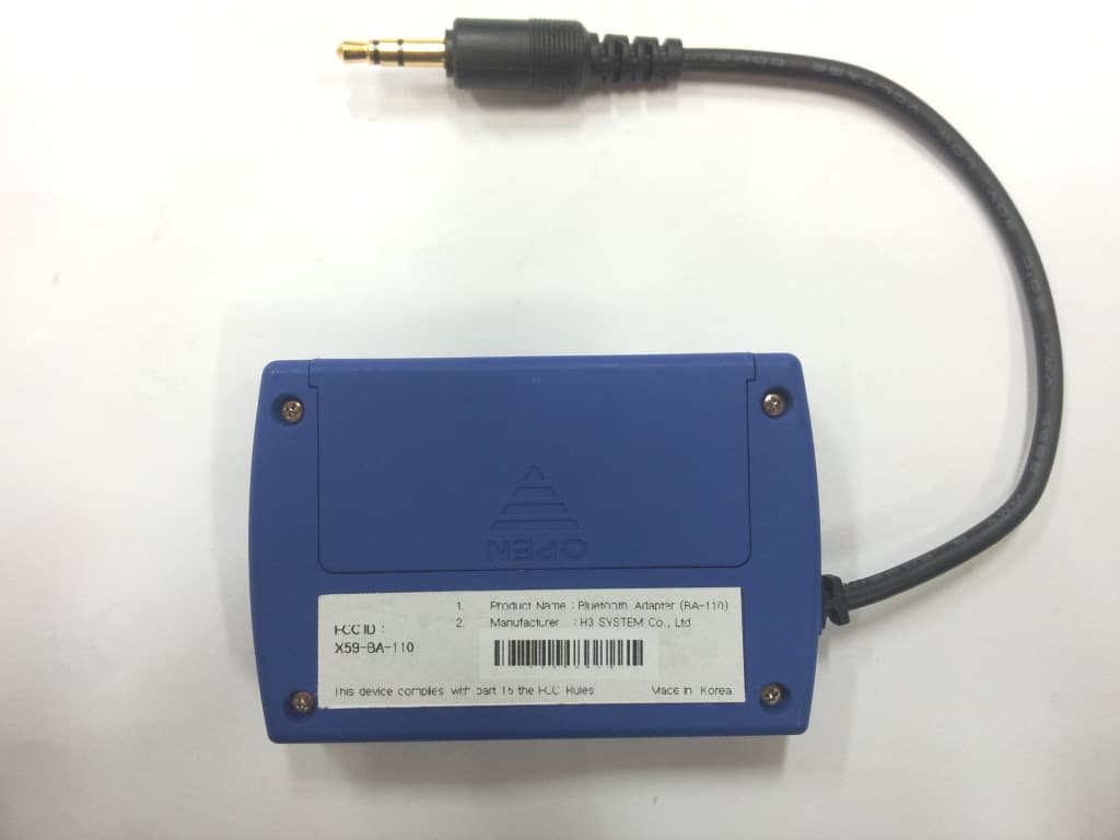
X59-BA-110
Dec 19, 2011Bluetooth Adapter
Equipment Class
DSS - Part 15 Spread Spectrum Transmitter
X59-H3G-700
Mar 10, 2011GSM/GPRS Gateway with Buuetooth
Equipment Class
DSS - Part 15 Spread Spectrum Transmitter