X59-H3G-800CDMA Gateway
H3 SYSTEM Co., Ltd.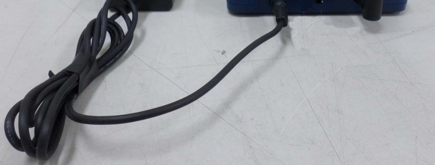
Click to zoom
Application Details
- Equipment Class
- DSS - Part 15 Spread Spectrum Transmitter
- Date of Grant
- May 18, 2015
- Application Purpose
- Original Equipment
- Date of Application
- May 18, 2015
- Equipment Note
- CDMA Gateway
- Frequency Range
- 2402.00000000 - 2480.00000000
- Company
- H3 SYSTEM Co., Ltd.
- Country
- South Korea
Documents & Files
Document Text
Text extracted from the exhibit documents filed with the FCC. Open a document above to read the original.
Users Manual
3G Gateway Instruction (H3G-800) H3 System Co., Ltd < Revision Notes > No. Date Version Content Author USA-Federal Communications Commission (FCC) This device complies with part 15 of the FCC Rules. Operation is subject to the following two conditions: (1) This device may not cause harmful interference, and (2) this device must accept any interference received, including interference that may cause undesired operation. This equipment has been tested and found to comply with the limits for a Class B digital device, pursuant to Part 15 of FCC Rules. These limits are designed to provide reasonable protection against harmful interference in a residential installation. This equipment generates, uses, and can radiate radio frequency energy. If not installed and used in accordance with the instructions, it may cause harmful interference to radio communications. However, there is no guarantee that interference will not occur in a particular installation. If this equipment does cause harmful interference to radio or television reception, which can be determined by tuning the equipment off and on, the user is encouraged to try and correct the interference by one or more of the following measures: - Reorient or relocate the receiving antenna - Increase the distance between the equipment and the receiver. - Connect the equipment to outlet on a circuit different from that to which the receiver is connected. - Consult the dealer or an experienced radio/TV technician for help. Any changes or modifications not expressly approved by the party responsible for compliance could void the user’s authority to operate the equipment. Warning This equipment should be installed and operated with separation distance of at least 20 cm from all persons. Welcome Thank you for purchasing 3G Gateway (H3G-800). The 3G gateway r eceive health data from devices such as blood pressure monitor, glucometer, and weight scale The 3G Gateway transmit them into a healthcare center through CDMA(verizon) mobile network Packaging List Modem Main AC Adapter (5V/3A) 0. Overview This document describes instructions regarding the H3 3G gateway (H3G-800, H3 System) and the related components. This document includes - How to install and configure the H3 3G gateway - How to use the H3 3G gateway - How to setup a server system for the H3 3G gateways 1. Specification 1. Dimension & weight - Size : 125 x 100 x33 mm - Weight : 160g - 2. Communication technology - Bluetooth : class 2 - Range : 10m - Profile : SPP (Serial Port Profile) - 3. Power supply : AC Adapter (5V/3A) or Rechargeable battery (Lithium polymer) 4. Frequency : Dual band (800, 1900MHz) 5. Operation temp : -10°C to 40°C(14 °F to 104 °F) 6. Antenna : External Quad band antenna 7. Available devices - Lifescan Onetouch Ultra/Mini with Bluetooth adapter(BA-110) - Weight : 160g - A&D weighting scale (UC-321PBT) - A&D blood pressure monitor (UA-767PBT) - IEM blood pressure monitor (Stabil-O-Graph) - ForaCare’s thermometer (FORA IR20b) - Beijing Choice’s Pulse Oximeter (MD300C318) 2. Gateway installation 1) Preparation for deployment A. SIM card i. Unscrew and open the bottom cover. And insert a SIM card. B. Gateway configuration i. Turn off the gateway. ii. Connect a serial cable (provided by H3 System) to a gateway and a PC. iii. Run the configuration software. iv. Turn on the gateway. v. Configure the gateway with the configuration software. For the details, please see the section below, “Gateway configuration.” C. Pairing and testing i. Pair with devices. Please see “Pairing” section below. ii. Take readings and confirm if the readings are successfully delivered to a server. Please see “Measurement and data transmission” section. Figure 1. SIM card insertion D. Final inspection i. Confirm the mode selection switch at “N.” If not, set the switch at “N.” ii. Prepare dry cells for backup batteries. iii. Close the bottom cover. 2) Installation at user’s home A. Place a gateway at a suitable place. B. Connect a power adapter. C. Insert dry cells if required. 8. Gateway configuration 1) Components A. A serial cable provided by H3 System B. Configuration software i. For admin: Serial numbers can be modified. ii. For user: Serial number change is not allowed. 2) Descriptions A. Configuration software for an admin: Serial No. modification is enabled. B. Items i. Open: Open the serial port ii. Setting: Shall be checked for changing gateway configurations iii. Serial No: Serial number of the gateway. It’s only enabled for the Admin version iv. IP(DNS): DataCollection Server IP or DNS v. Port: DataCollection Server port vi. Devices List: List of paired devices. Types and BT addresses. vii. Delete List: Delete all pairing info. viii. Clear Button: Clear window ix. Send Button: Send a new configuration to the gateway x. 3G Log: 3G AT-command logs 3) Steps A. Turn off the gateway. B. Connect a serial cable (provided by H3 System) to a gateway and a PC. C. Run the configuration software. D. Select the suitable COM port (You can check the COM port at the device manager.) and click “Open.” E. If you want to modify configuration, then check “Setting.” Otherwise uncheck “Setting.” F. Turn on the gateway. G. The current configuration and paired devices info are shown. H. Change the parameters and click “Send.” I. If you want to delete the pairing info, check “Delete List” and click “Send.” J. Before clicking “Send”, please double check the settings. K. Turn off the gateway and disconnect the serial cable. 9. Pairing 1) Mode selection switch A. “N”: Normal operation mode B. “P1”: Pairing mode as a slave. Used for A&D weighing scale (UC-321PBT) and blood pressure monitor (UA-767PBT). C. “P2”: Used for GMA (BA-110) for Lifescan’s blood glucose meter (OneTouch Ultra, OneTouch Mini/Easy, OneTouch Ultra2), IEM blood pressure monitor (Stabil-O- Graph), ForaCare’s thermometer (FORA IR20b), and Beijing Choice’s Pulse Oximeter(MD300C318). 2) Pairing process A. General process i. Turn off the gateway…
Text truncated - open the document above for the full version.
Cover Letter(s)
SCS-F18: Project and Product Certification Representative Authorization Letter Page 1 of 2 Rev 5.0 775 Montague Expressway Milpitas, CA 95035 Tel: 408-526-1188 Fax: 408-526-1088 Email: [email protected] Project and Product Certification Representative Authorization Letter Reason for Amendment (current / obsolete) Revision History Approved Date From To Initial Release (obsolete) 1.0 1.0 Nov-14-2006 Revised wording (obsolete) 1.0 2.0 Sept–25-2007 Updated company template (obsolete) 2.0 3.0 Jan-31-2012 Updated letter information (obsolete) 3.0 4.0 May-23-2014 Added FCC ID field (current) 4.0 5.0 Sept 16 2014 SCS-F18: Project and Product Certification Representative Authorization Letter Page 2 of 2 Rev 5.0 H3 SYSTEM Co., Ltd May.14.2015 To: SIEMIC, INC. 775 Montague Expressway, Milpitas, CA 95035 USA Dear Sir/Madam, Re: Product Certification Representative Authorization Letter We, H3 SYSTEM Co., Ltd. hereby authorize SIEMIC, Inc. to act as a Certification Body for certifying for the following project(s): (Product description : CDMA Gateway , model name : H3G-800) FCC ID: X59-H3G-800 Sincerely, Client’s signature : Client’s name / title : Sung-Dae Lim / Director Contact information / address : (Tamnip-dong), 283, Baeul 1-ro, Yuseong-gu Daejeon, South Korea 305-510
Cover Letter(s)
SCS-F19: Confidentiality Request Letter Page 1 of 3 Rev 4.0 775 Montague Expressway Milpitas, CA 95035 Tel: 408-526-1188 Fax: 408-526-1088 Email: [email protected] Confidentiality Request Letter Reason for Amendment (current / obsolete) Revision History Approved Date From To Initial Release (obsolete) 1.0 1.0 Nov-14-2006 Adding CFR 2.459 (obsolete) 1.0 2.0 August – 11 - 2008 Updated company template & Added text box (obsolete) 2.0 3.0 Jan-31-2012 Added IC confidentiality letter form (current) 3.0 4.0 March-26-2015 SCS-F19: Confidentiality Request Letter Page 2 of 3 Rev 4.0 H3 SYSTEM Co., Ltd May.14.2015 To: Federal Communications Commission Authorization and Evaluation Division 7435 Oakland Mills Road Columbia, MD Subject: Permanent Confidentiality Request for FCC ID: X59-H3G-800 We hereby request confidential treatment of information accompanying this application as outlined below: - Block Diagram - Schematics - Operational Description - Tune up Procedure - Part List The above materials contain trade secrets and proprietary information not customarily released to the public. The public disclosure of these materials may be harmful to the applicant and provide unjustified benefits to its competitors. The applicant understands that pursuant to Section 0.457 & 0.459 of the Rules, disclosure of this application and all accompanying documentation will not be made before the date of the Grant for this application. Sincerely, Client’s signature : Client’s name & title : Sung-Dae Lim / Director Contact information / address: : (Tamnip-dong), 283, Baeul 1-ro, Yuseong-gu Daejeon, South Korea 305- 510 SCS-F19: Confidentiality Request Letter Page 3 of 3 Rev 4.0
External Photos
1-1. FRONT External Photo 1-2. REAR 1-3.top of side 1-4.bottom of side 1-5.left of side 1-6.right of side
ID Label/Location Info
1. Product Name : 3G Gateway (H3G-800) 2. Manufacturer : H3 SYSTEM Co., Ltd. 3. FCC ID : X59-H3G-800 This device complies with part 15 the FCC Rules Made in Korea ** CDMA Gateway (H3G-800) Label 48 mm 24.5 mm
Internal Photos
3GC BOARD 1.1 Front INTERNAL PHOTO Antenna port 1.1-1 Front (cap off) 1.2 Rear LED BOARD 2.1 Front 2.2 Rear MAIN BOARD 3.1 Front 3.1-1 Front(cap off) BT Antenna 3.2 Rear ADAPTE R 4.1 Front 4.2 Rear 4.3 Label
RF Exposure Info
According to KDB 447498 D01 General RF Exposure Guidance v05, section 4.3.1 At 100 ㎒ to 6 ㎓ and for test separation distances ≤ 50 mm, the SAR test exclusion threshold is determined according to the following; a) [(max. power of channel, including tune-up tolerance, ㎽) / (min. test separation distance, mm)] x [√f(GHz)] ≤ 3.0 1. SAR test exclusion threshold GFSK Frequency : 2480 ㎒ (min. separation distances = 5 mm) SAR test exclusion thresholds(5 mm) = [(0.40 / 5) * √2.480] = 0.1259 ≤ 3.0. Mode Frequency (MHz) Tune up output Power (dBm) Measured max output power (dBm) Separation Distance (mm) ≤ 3.0 Bluetooth2 402-8.0±2-6.450.0770 Bluetooth2 441-7.0±2-5.8250.1 Bluetooth2 480-6.0±2-4.6550.1259 8DPSK Frequency : 2480 ㎒ (min. separation distances = 5 mm) SAR test exclusion thresholds(5 mm) = [(0.25 / 5) * √2.480] = 0.0787 ≤ 3.0. Mode Frequency (MHz) Tune up output Power (dBm) Measured max output power (dBm) Separation Distance (mm) ≤ 3.0 Bluetooth2 402-9.0±2-7.9450.0619 Bluetooth2 441-9.0±2-7.2850.0625 Bluetooth2 480-8.0±2-6.250.0787 2. Conclusion : Bluetooth SAR was not required Measured max output power = -6.2 dBm SAR test exclusion [Tune up power, dBm ] = [9Target power, dBm ± tune-up tolerance, dBm)] Maximum tuned up power = ( -6.0 dBm ± 2 dBm) = -4.0 dBm = 0.4 mW Measured max output power = -4.65 dBm [Tune up power, dBm ] = [9Target power, dBm ± tune-up tolerance, dBm)] Maximum tuned up power = ( -8.0 dBm ± 2 dBm) = -6.0 dBm = 0.25 mW
Test Report
4 5 6 7 10 10 10 10 12 16 16 4. Measurement condition .................................................................................... 5.1 Test procedure .......................................................................................... 6.1 Test procedure.......................................................................................... 5.4 Trace data ................................................................................................... 6. Maximum Peak Output Power ........................................................................... 5. Carrier Fre quency Separation ........................................................................... 5.2 Test instruments and measurement setup ...................................................... 5.3 Measurement results .................................................................................... Contents 1 1. Laboratory Information .................................................................................... 2. Descri ption of EUT .......................................................................................... 3. Test Standards ................................................................................................ EST-QP-20-01(2)-(F15) 16 16 17 17 17 17 18 22 22 22 22 23 25 7.3 Measurement results ................................................................................. ... Report Number : ESTF151504-002 , Web : www. estech. co. kr Page 2 of 62 7. Number of Hopping Frequency ........................................................................... 7.1 Test procedure .......................................................................................... 7.2 Test instruments and measurement setup ...................................................... 7.4 Trace data ................................................................................................ 8. Time of Occu pancy (Dwell Time) ........................................................................ 8.1 Test procedure .......................................................................................... 8.3 Measurement results .................................................................................... 8.5 Trace Data ................................................................................................... 8.2 Test instruments and measurement setup ...................................................... 8.4 Trace Data ................................................................................................... 6.1 Test procedure 6.2 Measurement results ................................................................................. ... EST-QP-20-01(2)-(F15) 27 27 27 27 28 36 36 36 37 41 45 9. Band-edge and Out of band emissions ............................................................ ... 9.1 Test procedure .......................................................................................... Contents 2 10.3 Test data (Bluetooth Basic Rate) ............................................................... 10.4 Restricted Band Edges (Bluetooth Basic Rate) ............................................. 9.2 Test instruments and measurement setu p ...................................................... 9.3 Measurement results of band-edge & out of emission ....................................... 10.1 Measurement equipment ........................................................................... 10.2 Environmental conditions ........................................................................... 9.4 Trace data of band-edge & out of emission ................................................... 10. Measurement of radiated emission ............................................................... ... 10.5 Test data(Bluetooth EDR) ........................................................................... EST-QP-20-01(2)-(F15) 49 53 11.1 Measurement e quipment ...........................................................................53 11.2 Environmental conditions ........................................................................ ...53 54 56 56 57 58 59 12.4. Photogra phs of EUT.................................................................................... 12. Photographs of test setup ................................................................................. 12.1.Setu p for Radiated Test : 30 ~ 1 000 MHz ................................................... Report Number : ESTF151504-002 , Web : www. estech. co. kr Page 3 of 59 10.6 Restricted Band Edges (Bluetooth Basic EDR) ................................................ Appendix 1. Special diagram Appendix 2. Antenna Requirement 11. Measurement of conducted emission ............................................................... ... 11.3 Test data (Bluetooth Basic Rate / EDR) ......................................................... 12.2. Setup for Radiated Test :Above 1 000 MHz ................................................ 12.3. Setu p for Conducted Test : 0.15 ~ 30 MHz ................................................ EST-QP-20-01(2)-(F15) 1. Laboratory Information 1.1 General 1.2 Test Lab. Corporation Name : ESTECH Co., Ltd. Head Office : Suite 1015 World Meridian III , 123 Gasan Digital 2-ro, Geumcheon-gu, Seoul 153-759, R.O. Kore EMC/Telecom/Safety Test Lab : 97 1 Hoeeok ri Majang myun Ichion city Gyonggi do R O Korea This EUT (Equipment Under Test) has been shown to be capable of compliance with the applicable technical standards and is tested in accordance with the measurement procedures as indicated in this report. ESTECH Lab attests to accuracy of test data. All measurement reported herein were performed by ESTECH Co., Ltd. ESTECH Lab assume full responsibility for the completeness of these measurements and vouch for the qualifications of all persons taking them. EST-QP-20-01(2)-(F15) EMC/Telecom/Safety Test Lab : 97-1, Hoeeok-ri, Majang-myun, Ichion-city, Gyonggi-do, R.O. Korea 1.3 Official …
Text truncated - open the document above for the full version.
Test Setup Photos
1. Photographs of test setup (Bluetooth) 1-1.Setup for Radiated Test : (30 ~ 1 000) MHz [ Front ] TEST SETUP PHOTO [ Rear ] 1-2. Setup for Radiated Test : Above 1 000 MHz [ Front ] [ Rear ][ Rear ] 1-3. Setup for conducted disturbance [ Front ] [ Rear ]
Contact Information
Applicant
Sung-Dae Lim(Director)
Test Firm
ESTECH CO., LTDJin Mo Yang
Technical Specifications
| # | Rule Parts | Frequency Range | Power Output |
|---|---|---|---|
| 1 | 15C | 2.40 GHz - 2.48 GHz | 343.00 µW |
Other Applications from H3 SYSTEM Co., Ltd.
X59-HRM-3200
Mar 23, 2015Heart Rate Monitor
Equipment Class
DTS - Digital Transmission System
X59-H3G-650
Apr 15, 2012CDMA Gateway
Equipment Class
DSS - Part 15 Spread Spectrum Transmitter
X59-HRM-1000
Mar 19, 2012Heart Rate Monitor
Equipment Class
DTS - Digital Transmission System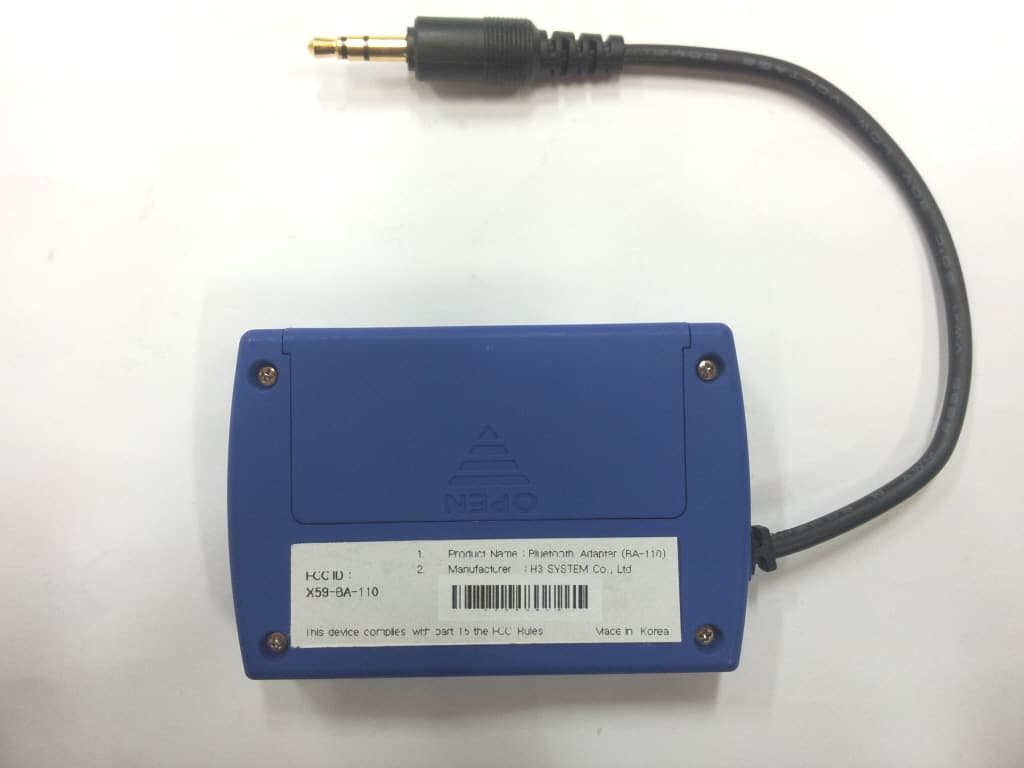
X59-BA-110
Dec 19, 2011Bluetooth Adapter
Equipment Class
DSS - Part 15 Spread Spectrum Transmitter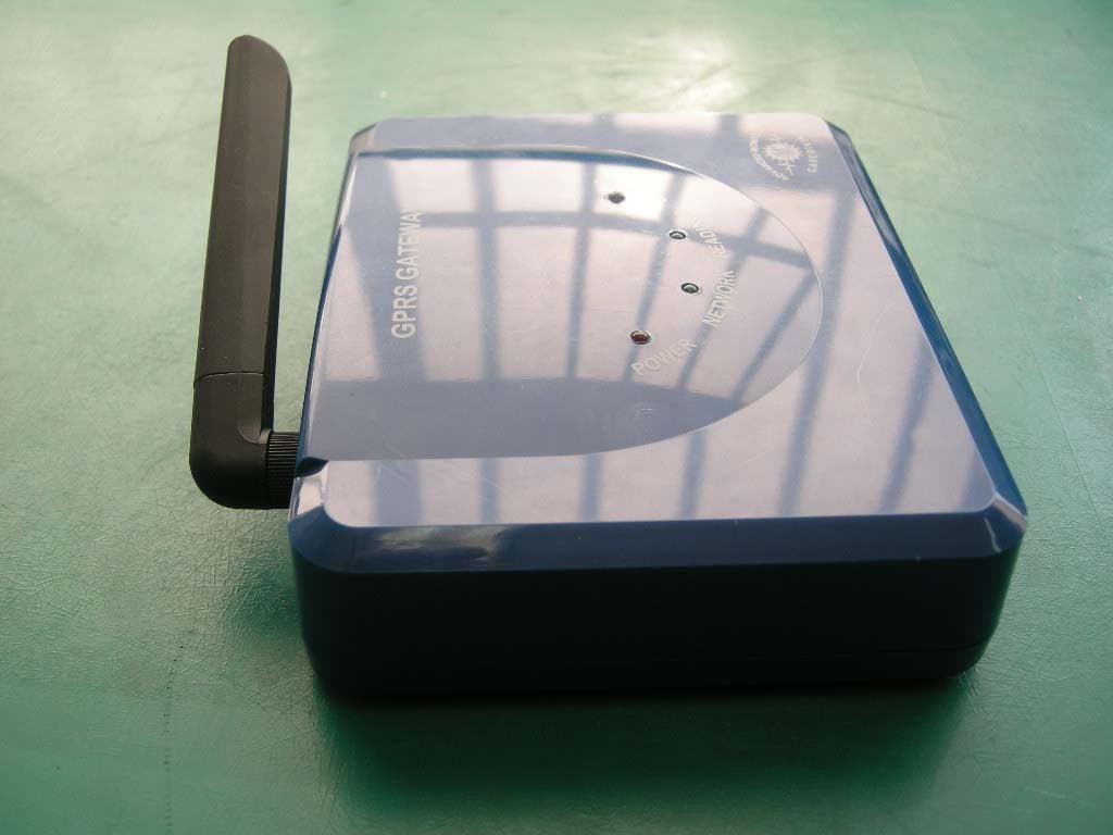
X59-H3G-700
Mar 10, 2011GSM/GPRS Gateway with Buuetooth
Equipment Class
DSS - Part 15 Spread Spectrum Transmitter