X59-HRM-1000Heart Rate Monitor
H3 SYSTEM Co., Ltd.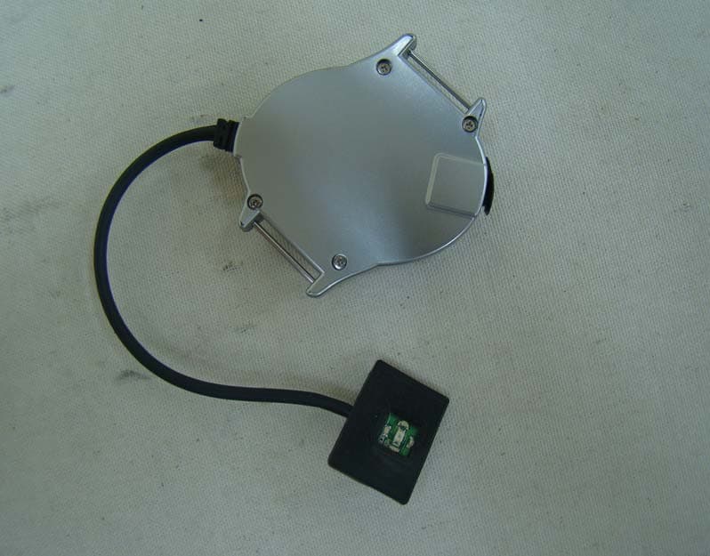
Click to zoom
Application Details
- Equipment Class
- DTS - Digital Transmission System
- Date of Grant
- Mar 19, 2012
- Application Purpose
- Original Equipment
- Date of Application
- Mar 19, 2012
- Equipment Note
- Heart Rate Monitor
- Frequency Range
- 2405.00000000 - 2480.00000000
- Company
- H3 SYSTEM Co., Ltd.
- Country
- South Korea
Documents & Files
Document Text
Text extracted from the exhibit documents filed with the FCC. Open a document above to read the original.
Users Manual
Heart Rate Monitor (HRM-1000) User’s Manual H3 System Co., Ltd. I. General Description This device is to measure heart rate and being composed of main body (wrist watch), sensing part, gloves, a charging adapter and a software (Optional). Main body and the sensing part is connected to each other and can be mounted on the glove. The measurement principle is based on the optics. The amount of the reflected light compared to the acting light is measured at the sensing part. The change of the light reflectance is thereafter analyzed to calculate heart rate at the main body(wrist watch). Calculated pulses are displayed on the LCD screen of wrist watch, and can be wirelessly transmitted to other devices, PC or smart phone. This device uses a rechargeable battery and can be charged through DC adapter. II. Component Description 1. Heart rate monitor ① Main body (wrist watch): The main body is central processing part composed of LCD display, start-stop button, measurement button, communications terminals and a built-in communication module. Ⓐ communication terminal: IN-OUT serial communication port Ⓑ LCD display : LCD screen that displays various information. Ⓒ "S" (Start / Stop) Button: power ON / OFF Ⓓ "M" (Measurement) Button: Start measurement. ② Sensor cable: Connect the main body and the sensing part that makes it possible to transfer the information. ③ Gloves ④ Sensor mounts : a sensor fixation part ⑤ Wrist strap ⑥ Sensing part : optical parts which measures PPG(Photo plethysmography) signal. It measures the amount of the reflected light compared to the acting light at the finger III. Using a heart rate monitor 1. Wearing and power-on the device (1) Wearing heart rate monitor gloves * Caution : When you wear gloves, please fasten the finger strap not too loose after confirming that the sensing part is located on the root part of first joint of the index finger. The wrist strap (wrist fasteners) should be fasten tightly not to move around a wrist. (2) Press the ‘S(start)’ button : LCD is ON and displays the device ID and the current settings. - The status of the monitor is marked as dot, '•', to the left of the display. The modes are ‘Set’, ‘Mode’ and ‘Com’. By default, '•' should appear at ‘Set’ and ‘Com’ at the same time. 2. Heart rate measurement (1) In order to start the heart rate measurement, press "M (Measure On)" button. * Measuring Notes The initial 10 seconds are needed to initialize the measurement, it is recommended during this first 10 seconds not to move your fingers and hands, and make your hands as if holding an egg lightly. (2) If the 10 seconds initialization is successful, the heart rate monitor displays your current heart rate at the top of the LCD display. *. Notice In some cases (not usual), If it displays zero ‘0’ for a while, It is recommended to press the ‘M'(Measure Off) button to stop measuring and restart monitor after re- worn the device. (3) During exercise, any of the buttons should not be pressed. 3. After using the heart rate monitor. (1) In order to terminate the heart rate measurement, press ‘S (Stop)’ button. The heart rate monitor will turn off all display. After you wear off the gloves, please be kept charged by plugging in the adapter. (2) Pressing ‘S(stop)’ button, If the monitor displays 'BUSY', you should not do any operation and let it terminate automatically. 4. How to store and maintenance (1) Storage environment : Temperature -10~55 °C, humidity is kept at less than 95%. (2) The following points should be taken when storing. ① not exposed to corrosive gases. ② should be kept away from moisture and dust. ③ should be kept clean. 5. Precautions during use (1) Ware the sensing part with care to avoid application of excessive force. (2) Remain stop during 10 to 20 seconds after pressing the ‘M(measure)’ button (3) Do not stare at the light of the sensing part since the LED light is harmful if you stare on. (4) This device was developed for purposes described in this manual and the manufacturer is not responsible for side effects caused by an improper purpose or improper use. (5) Before using the device and accessory, please check and confirm that there is no faulty. When in doubt, do not use and notify the manufacturer or service center immediately. (6) This device should be repaired by an approved person and approved organizations. (7) This device should not be repaired by user itself. (8) Use only standardized accessories which is provided with this device. IV. Electrical rating (1) The type and degree of protection to protect against electrical shock : The internal power-type equipment, BF-type mounting (2) Electrical Rating: DC 3.7V Lithium polymer battery V. Matters (1) The product name, model name (model): heart rate monitor (HRM-1000) (2) the manufacturer's name and address: - Company Name : H3 System Co., Ltd. - Address: 3 rd floor, Daedeok Bldg., 397-27, Doryong-dong, Yuseong-gu, Daejeon city, Korea (republic of) - Phone : +81-42-862-9313~4 - Homepage : http://www.h3system.co.kr (3) manufacturer’s authorization and manufacturing product license number - Manufacturer’s authorization: listed after approval - Manufacturing product license number: listed after approval (4) The manufacture’s serial number, manufacturing date, weight, packaging unit - manufacture’s serial number: listed after manufacture - Date of Manufacture: listed after manufacture - Weight: 60g (excluding charging adapter) - Packing: 1set (5) How to use (including performance), and use precautions or warnings, Storage: written at a separate attachment (6) Purpose: To measure and display heart rate during exercise. (7) Other necessary matters ① The type and degree of protection to protect against electrical shock : The internal power-type equipment, BF-type mounting ② Electrical Rating: DC 3.7V Lithium polymer battery (8) This device is for medical equipment (in Korea). ※ The above information is listed on the back of the device, packaging and attachments. Regulatory Statements…
Text truncated - open the document above for the full version.
Cover Letter(s)
H3 SYSTEM Co., Ltd. Date : January 9, 2012 Compliance Certification Services Certification Division 561F Monterey Road Morgan Hill, CA 95037 To whom it may concern: We, the undersigned, hereby authorize <ESTECH CO.,Ltd.>, to act on our behalf in all manners relating to application for equipment authorization, including signing of all documents relating to these matters. Any and all acts carried out by <ESTECH CO., Ltd.> on our behalf shall have the same effect as acts of our own. We, the undersigned, hereby certify that we are not subject to a denial of federal benefits, that includes FCC benefits, pursuant to Section 5301 of the Anti-Drug Abuse Act of 1988, 21 U.S.C. 853(a). In authorizing <ESTECH CO.,Ltd.> as our agent, we still recognize that we are responsible to: a) comply with the relevant provisions of the certification program; b) make all necessary arrangements for the conduct of the evaluation, including provision for examining documentation and access to all areas, records (including internal audit reports) and personnel for the purposes of evaluation (e.g. testing, inspection, assessment, surveillance, reassessment) and resolution of complaints; c) make claims regarding certification only in respect of the scope for which certification has been granted; d) do not use our product certification in such a manner as to bring the Certification Division into disrepute and not make any statement regarding our product certification which the Certification Division may consider misleading or unauthorized; e) upon suspension or cancellation of certification, discontinue use of all advertising matter that contains any reference thereto and return any certification documents as required by the Certification Division; f) use certification only to indicate the products are certified as being in conformity with specified standards; g) endeavor to ensure that no certificate or report nor any part thereof is used in a misleading manner; h) ensure that any reference to our product certification in communication media such as documents, brochures or advertising, complies with the requirements of the Certification Division; i) keep a record of all complaints made known to the us relating to the product’s compliance with requirements of the relevant standard and to make these records available to the Certification Division when requested; j) take appropriate action with respect to such complaints and any deficiencies found in products or services that affect compliance with the requirements for certification; k) document the actions taken. This authorization is valid until further written notice from the applicant. Sincerely Yours, Sign Kim, Young-Hwa / Senior engineer REMARK: 1. This authorization letter will be sent along with your application when filing with the Certification Division. 2. Please follow the format and type it on company letterhead and send original to us.
Cover Letter(s)
H3 SYSTEM Co., Ltd. 3F,397-27,Doryong-dong,Yuseong-gu,Daejeon, R.O.Korea TEL : 82-42-862-9314 FAX : 82-42-862-9315 Federal Communications Commission Authorization and Evaluation Division FCC ID : X59-HRM-1000 Confidentiality Request Pursuant to Sections 0.457 and 0.459 of the Commission’s Rules, the Applicant hereby requests confidential treatment of information accompanying this Application as outlined below: Schematics Block Diagram The above materials contain trade secrets and proprietary information not customarily released to the public. The public disclosure of these matters might be harmful to the Applicant and provide unjustified benefits to its competitors. The Applicant understands that pursuant to Rule 0.457, disclosure of this Application and all accompanying documentation will not be made before the data of the Grant for this application. Sincerely, Sign Kim, Young-Hwa / Senior engineer
External Photos
1. FRONT 2. REAR 3. PORT
ID Label/Location Info
H3 SYSTEM Co., Ltd. Heart Rate Monitor MODEL : HRM-1000 FCC ID:X59-HRM-1000 This device complies with part 15 or rhe FCC Rules. Operation is subject to the dollowing two conditions : (1) This device may not cause harmful interference, and (2) this device must accept ant interference received, including interference that may cause undesired operation.
Internal Photos
INTERNAL PHOTO 1. Main Board 1.1 Front 1.2 Rear 2. Sensor Board 2.1 Front 2.1 Front 3.Adapter 3.1 Front 3.2 Rear 4. ZIGBEE Board 4.1 Front 4.2 Rear
Operational Description
MG245X Datasheet VER.2.01 The reproduction of this datasheet is NOT allowed without approval of RadioPulse Inc. All information and data contained in this datasheet are subject to change without notice. This publication supersedes and replaces all information previously supplied. RadioPulse Inc. has no responsibility to the consequence of using the patents describes in this document. MG245X-DS-001 MG245X Datasheet VER.2.01 Page:2/195 www.radiopulse.co.kr REVISION HISTORY Version Date Description VER.1.0 2008.1.19 ▪ First Official Version Release VER.1.1 2008.1.24 ▪ Section 5 -Delete the followings in the Table 1. P0[0]:SCKO of SPI master P0[5]:SSB of SPI slave P0[6]:SDO of SPI slave P0[2]:MISO of SPI master P0[3]:SPICSNI P0[7]:SDI of SPI slave P0[1]:MOSI of SPI master P0[4]:SCKI of SPI slave ▪ Section 7.6.7 -Modify SPER(SPI E REGISTER) -> SPER(SPI EXTENDED REGISTER) ▪Section 7.6.12 -Modify SADCREF of SADCCON register VER.1.2 2008.2.28 ▪Section 3 -Correct Typing Error(-99dBm -> -98dBm: High RF RX Sensitivity) ▪Section 6 - Add „NOTE‟ ▪Section 7.2 - Add „NOTE‟ ▪Section 7.5 -PM3: Change from 1A to 0.3A. ▪Section 10 -Add Blocking/Desensitization -PM3: Change from 1A to 0.3A. VER.1.3 2008.4.10 ▪Section 4 - Modify Power ▪[Figure 2] - AVDD_XOSC -> DVDD_XOSC ▪[Table 1] -PIN H4: Modify Pin Description -PIN B5/B6 (AVDD_XOSC -> DVDD_XOSC ) MG245X-DS-001 MG245X Datasheet VER.2.01 Page:3/195 www.radiopulse.co.kr ▪Section 6 -Modify entire contents ▪Section 7.3 -Modify contents(Add CLKDIV0 ) ▪Section 7.6.14 / 7.6.15 -Modify [Figure 18] / [Figure 19] and contents ▪Section 7.8.2 -Entire contents of PLL0/1/2/3 (PLL CONTROL 0/1/2/3 REGISTER, 0x2286, 0x2287, 0x2288, 0x228B) VER.1.31 2008.6.19 ▪Section 7.6.3 -Modify WDTCON. WDTWE: Modify Description. WDTEN: Modify Reset Value(0->1) WDTPRE: Modify Reset Value(0->11) ▪Section 7.7.3 -Modify MTFCSTS. Full: Modify R/W part(R/W ->R/O) Empty: Modify R/W part(R/W ->R/O) VER.1.4 2008.7.20 ▪Section 7.1.1 -Add the address table of code banking including common area. ▪Section 7.5 -Modify entire contents. ▪Section 7.6.4 -Modify entire contents. - Add „Note‟. ▪Section 7.6.8 -Add „Note‟ for ADPCM. ▪Section 7.6.10 -Add „Note‟ in the bit field 0(mode) of QCTL. ▪Section 7.6.14 -Add „Note‟. MG245X-DS-001 MG245X Datasheet VER.2.01 Page:4/195 www.radiopulse.co.kr ▪Section 7.6.15 -Add „Note‟. VER.1.41 2008.12.8 ▪Section 9 - Change V DD to V DDIO on V IH , V IL , V OH ▪Section 7.2 -Add NOTE ▪Section 8,9 - Change MAX value 2.0 to 1.65 on VDD - Change MAX value 3.6 to 3.3 on VDDIO ▪Section 7.6.4 - Modify NOTE VER.1.42 2009.2.13 ▪Section 7.1.4 - Change „P3OEN, P0OEN‟ initial/reset value to 0xFF, „P1OEN‟ initial/reset value to 0xEF. ▪Section 7.8.1 - RX End Interrupt (RXEND_INT) Correct „TX FIFO‟ to „RX FIFO‟ ▪Section 7.8.2 -PCMD0 (PHY COMMAND0 REGISTER, 0x2200) Name RXON : Contents corrected - PCMD1 (PHY COMMAND1 REGISTER,0x2201) Name RXOFF : Contents corrected -RXRFPU (RF RX PATH POWER-UP REGISTER, 0x2205) Name LNAPU : Contents corrected -TXRFPD (RF TX PATH POWER-DOWN REGISTER, 0x2206) Name TXUMBUFPD : Contents corrected -PHYSTS1 (PHY STATUS1 REGISTER, 0x2271) Name TXSTSF, MDSTSF : Contents corrected VER.1.5 2009.2.27 ▪Section 6 -Modify „application circuit‟ ▪Section 7.2 -Delete Reset Errata. MG245X-DS-001 MG245X Datasheet VER.2.01 Page:5/195 www.radiopulse.co.kr ▪Section 7.5 -Add PDM Register, PDCON Register ▪Section 7.6.4 -Change RTEN to STEN bit in PDCON ▪Section 7.6.5 -Add RCOSC1 Register VER.1.51 2009.6.22 ▪Section 7.5 - Modify reset value of PDM, PDCON register. ▪Section 7.6.5 -Modify reset value of RCOSC1 register. ▪Section 7.8.2 -Change „TDCNF0‟ to „TDCNF3‟, „TDCNF1‟ to „TDCNF0‟. VER.2.0 2009.12.10 ▪Section 7.1.4 - P1OEN/P0REN/P1REN/P3REN reset value modified. ▪Section 7.6.11 - Contents modified. ▪Section 7.6.12 - Modify „8KHz‟ to „16KHz‟. - SADCCON - SADCDONE, SADCREF contents modified. - SADCVALH - contents modified. - SADCVALL - contents modified. - SADCBIASH, SADCBIASL delete. ▪Section 7.6.14 - contents and note modified. ▪Section 7.6.15 - contents and note modified. ▪Section 10. - Add PM1 max value. ▪All section - Datasheet of MG2450 and of MG2455 are combined. VER.2.01 2010.4.1 ▪Section 7.6.4. - RTDLY description and reset value are changed. MG245X-DS-001 MG245X Datasheet VER.2.01 Page:6/195 www.radiopulse.co.kr CONTENTS 1. INTRODUCTION ........................................................................................... 11 2. APPLICATIONS ............................................................................................ 11 3. ENHANCED FEATURES ............................................................................... 12 4. FEATURES .................................................................................................... 12 5. PIN DESCRIPTION ....................................................................................... 14 6. APPLICATION CIRCUIT................................................................................ 24 7. FUNCTIONAL DESCRIPTION....................................................................... 32 7.1. MEMORY ORGANIZATION ........................................................................ 34 7.1.1. PROGRAM MEMORY ....................................................................... 34 7.1.2. DATA MEMORY ................................................................................ 37 7.1.3. GENERAL PURPOSE REGISTERS ................................................. 38 7.1.4. SPECIAL FUNCTION REGISTERS .................................................. 39 7.2. RESET ....................................................................................................... 51 7.3. CLOCK SOURCE ....................................................................................... 51 7.4. INTERRUPT SCHEME ............................................................................... 52 7.5. POWER MANAGEMENT ........................................................................... 58 7.6. ON-CHI…
Text truncated - open the document above for the full version.
RF Exposure Info
Limit According to 15.247(i), systems operating under the provisions of this section shall be operated in a manner that ensures that the public is not exposed to radio frequency energy levels in excess of the Commission's guidelines. See 1.1307(b)(1) of this chapter. EUT Specification Bluetooth : 2.402 GHz ~ 2.480 GHz WLAN : 2.412 GHz ~ 2.462 GHz WLAN : 5.745 GHz ~ 5.825 GHz WLAN : 5.18 GHz ~ 5.32 GHz / 5.50 GHz ~ 5.70 GHz Portable(< 20 cm separation) Portable(> 20 cm separation) Others Occupational/Controlled exposure(S = 5 mW/cm 2 ) General Population/Uncontrolled exposure(S=1 mW/cm 2 ) Single antenna Multiple antennas Tx diversity Rx diversity Tx/Rx diversity Max. output power 5.7 dBm (3.68 mW) Antenna gain(Max) 2 dBi (Numberic gain:2.238) MPE Evaluation SAR Evaluation N/A Remark : 1. The maximum output power is 5.7 dBm(3.68 mW) at 2405 MHz ( with 2.238 numeric antenna gain.) 2. DSS device is not subject to routine RF evaluation;MPE estimate is used to justify the compliance. 3. For mobile or fixed location transmitters, no SAR consideration applied. The maximum power density is 1.0 mW/cm 2 even if the calculation indicates that the power density would be larger. Test Results No non-compliance noted. (SAR evaluation is not required for the Portable device while its maximum output power is lower than the general population low threshold: 60/f(GHz)=60/2.405=24.95 mW) Evalution applied EUT Frequency band (Operating) Device category Radio Frequency Exposure Heart Rate Monitor Exposure Classification Antenna diversity
Test Report
Test Report for FCC Company name Address Telephone Product name Model No. Serial No. Test date Testing location Standard Tested by Reviewed by Abbreviation * Note - This test report is not permitted to copy partly without our permission - This test result is dependent on only equipment to be used - This test result based on a single evaluation of one sample of the above mentioned OK, Pass = Complied, Fail = Failed, N/A = not applicable H3 SYSTEM Co., Ltd. 3F, 397-27, Doryong-dong, Yuseong-gu, Daejeon, R.O.Korea 82-42-862-9314 Measurement facility registration number Engineer J.H. KIM Engineering Manager J.M.Yang 94696 (Signature) HRM-1000 NONE H3 SYSTEM Co., Ltd. KOREA FCC PART 15 2010 , ANSI C 63.4 2003 2011-12-29 ~2011-12-30 Heart Rate Monitor Date of issue ESTECH Co., Ltd. 58-1 OSan-Ri Kanam-Myon, Yeoju-Gun, KyungKi-Do, Korea (Signature) FCC ID:X59-HRM-1000 Report Number : ESTF151201-005 , Web : www. estech. co. kr Page 1 of 27 Report NumberESTF151201-005 Manufacturer Country of origin Applicant Product 13-Jan-12 3 4 5 6 9 9 9 9 10 12 12 12 13 13 13 13 14 16 16 16 16 17 21 21 21 22 26 10.1 Measurement equipment ........................................................................ 26 10.2 Environmental conditions ........................................................................ 26 27 7.2 Test instruments and measurement setu p ...................................................... 7.3 Measurement results .................................................................................... 7.4 Trace data ................................................................................................... 8. Band-Edge and Out of Band Emissions ............................................................... 9.2 Environmental conditions .............................................................................. 9.3 Test data ................................................................................................... 8.1 Test procedure .......................................................................................... 8.2 Test instruments and measurement setup ...................................................... 8.3 Measurement results .................................................................................... 8.4 Trace data of band-edge & out of emissioin ................................................... 9. Measurement of radiated emission ..................................................................... 9.1 Measurement equipment .............................................................................. 5.2 Test instruments and measurement setup ...................................................... 5.3 Measurement results .................................................................................... 5.4 Trace data ................................................................................................... 6. Maximum Peak Output Power ........................................................................... 6.1 Test procedure .......................................................................................... 6.2 Measurement results .................................................................................... 7. Transmitter Power Spectral Density ..................................................................... 7.1 Test procedure .......................................................................................... 5. 6dB Bandwidth Measurement ........................................................................... 5.1 Test procedure .......................................................................................... Contents 1. Laboratory Information .................................................................................... 2. Descri ption of EUT .......................................................................................... 3. Test Standards ................................................................................................ 4. Measurement condition .................................................................................... Report Number : ESTF151201-005 , Web : www. estech. co. kr Page 2 of 27 10. Measurement of conducted emission ............................................................... Appendix 2. Antenna Requirement 10.3 Test data ................................................................................................ Appendix 1. Special diagram 1. Laboratory Information 1.1 General 1.2 Test Lab. Corporation Name : ESTECH Co., Ltd. Head Office : Rm 1015, World Venture Center II, 426-5, Gasan-dong, Geumcheon-gu, Seoul, Korea (Safety & Telecom. Test Lab) EMC Test Lab : 58-1 Osan-Ri, GaNam-Myon, YeoJoo-Gun, KyungKi-Do, Korea 97-1 Hoiuk-Ri Majang-Myon, Icheon-city, KyungKi-Do, Korea 1.3 Official Qualification(s) MIC : Granted Accreditation from Ministry of Information & Communication for EMC, Safety and Telecommunication KOLAS : Accredited Lab By Korea Laboratory Accreditation Schema base on CENELEC requirements FCC : Filed Laboratory at Federal Communications Commission VCCI : Granted Accreditation from Voluntary Control Council for Interference from ITE This EUT (Equipment Under Test) has been shown to be capable of compliance with the applicable technical standards and is tested in accordance with the measurement procedures as indicated in this report. ESTECH Lab attests to accuracy of test data. All measurement reported herein were performed by ESTECH Co., Ltd. ESTECH Lab assume full responsibility for the completeness of these measurements and vouch for the qualifications of all persons taking them. Report Number : ESTF151201-005 , Web : www. estech. co. kr Page 3 of 27 2. Description of EUT 2.1 Summary of Equipment Under Test Product Name: Model Number: HRM-1000 Modulation Type: Transfer Rate: Number of Channel : 16 Channel Spacing: Output Power: Serial Number: Manufacturer: Country of origin: Rating : Receipt Date: 2.2 General descriptio…
Text truncated - open the document above for the full version.
Test Setup Photos
TEST SETUP PHOTO 1. Conducted emission setup photo 1.1 Front 1 2 Rear 1.2. Rear 2. Radiated Emission setup photo 2.1. Front 2.2. Rear 3. Radiated Emission setup photo (Above 1000 MHz) 3.1 Front 3.2 Rear
Contact Information
Applicant
Sung-Dae Lim(Director)
Test Firm
ESTECH Co., Ltd.Yang Jinmo
Technical Specifications
| # | Rule Parts | Frequency Range | Power Output |
|---|---|---|---|
| 1 | 15C | 2.40 GHz - 2.48 GHz | 4.00 mW |
Other Applications from H3 SYSTEM Co., Ltd.
X59-H3G-800
May 18, 2015CDMA Gateway
Equipment Class
DSS - Part 15 Spread Spectrum Transmitter
X59-HRM-3200
Mar 23, 2015Heart Rate Monitor
Equipment Class
DTS - Digital Transmission System
X59-H3G-650
Apr 15, 2012CDMA Gateway
Equipment Class
DSS - Part 15 Spread Spectrum Transmitter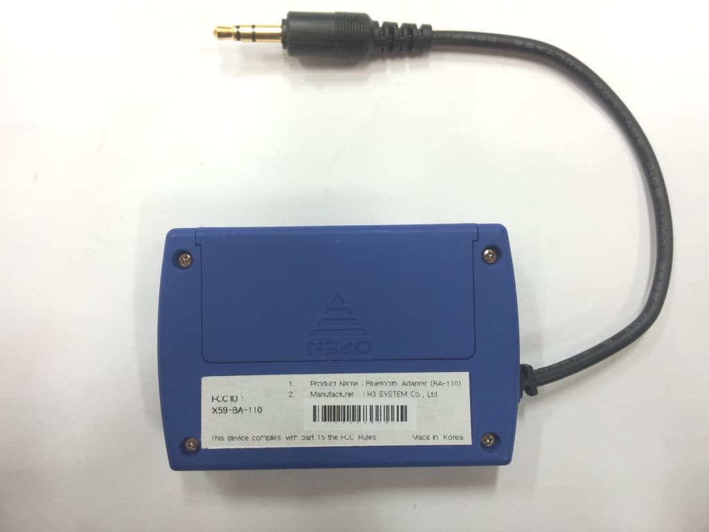
X59-BA-110
Dec 19, 2011Bluetooth Adapter
Equipment Class
DSS - Part 15 Spread Spectrum Transmitter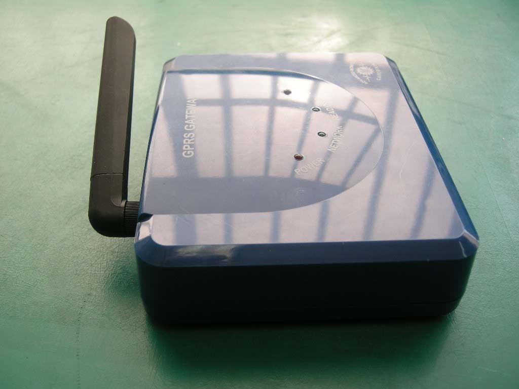
X59-H3G-700
Mar 10, 2011GSM/GPRS Gateway with Buuetooth
Equipment Class
DSS - Part 15 Spread Spectrum Transmitter