X59-H3G-650CDMA Gateway
H3 SYSTEM Co., Ltd.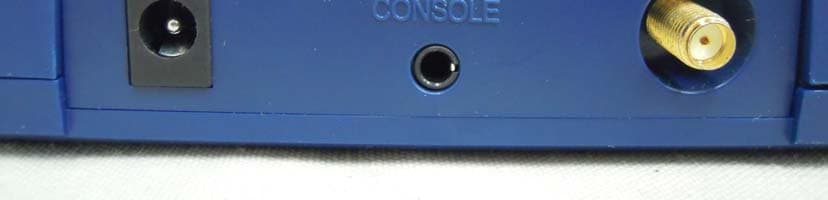
Click to zoom
Application Details
- Equipment Class
- DSS - Part 15 Spread Spectrum Transmitter
- Date of Grant
- Apr 15, 2012
- Application Purpose
- Original Equipment
- Date of Application
- Apr 15, 2012
- Equipment Note
- CDMA Gateway
- Frequency Range
- 2402.00000000 - 2480.00000000
- Company
- H3 SYSTEM Co., Ltd.
- Country
- South Korea
Documents & Files
Document Text
Text extracted from the exhibit documents filed with the FCC. Open a document above to read the original.
Users Manual
CDMA Gateway Instruction (H3G-650) H3 System Co., Ltd < Revision Notes > No. Date Version Content Author 0. Overview This document describes instructions regarding the H3 CDMA gateway (H3G-650, H3 System) and the related components. This document includes - How to install and configure the H3 CDMA gateway - How to use the H3 CDMA gateway - How to setup a server system for the H3 CDMA gateways 1. Gateway installation 1) Preparation for deployment A. SIM card i. Unscrew and open the bottom cover. And insert a SIM card. B. Gateway configuration i. Turn off the gateway. ii. Connect a serial cable (provided by H3 System) to a gateway and a PC. iii. Run the configuration software. iv. Turn on the gateway. v. Configure the gateway with the configuration software. For the details, please see the section below, “Gateway configuration.” C. Pairing and testing i. Pair with devices. Please see “Pairing” section below. ii. Take readings and confirm if the readings are successfully delivered to a server. Please see “Measurement and data transmission” section. D. Final inspection i. Confirm the mode selection switch at “N.” If not, set the switch at “N.” ii. Prepare dry cells for backup batteries. iii. Close the bottom cover. 2) Installation at user’s home A. Place a gateway at a suitable place. B. Connect a power adapter. C. Insert dry cells if required. 2. Gateway configuration 1) Components A. A serial cable provided by H3 System B. Configuration software i. For admin: Serial numbers can be modified. ii. For user: Serial number change is not allowed. 2) Descriptions Figure 1. SIM card insertion A. Configuration software for an admin: Serial No. modification is enabled. B. Items i. Open: Open the serial port ii. Setting: Shall be checked for changing gateway configurations iii. Serial No: Serial number of the gateway. It’s only enabled for the Admin version iv. IP(DNS): DataCollection Server IP or DNS v. Port: DataCollection Server port vi. Devices List: List of paired devices. Types and BT addresses. vii. Delete List: Delete all pairing info. viii. Clear Button: Clear window ix. Send Button: Send a new configuration to the gateway x. CDMA Log: CDMA AT-command logs 3) Steps A. Turn off the gateway. B. Connect a serial cable (provided by H3 System) to a gateway and a PC. C. Run the configuration software. D. Select the suitable COM port (You can check the COM port at the device manager.) and click “Open.” E. If you want to modify configuration, then check “Setting.” Otherwise uncheck “Setting.” F. Turn on the gateway. G. The current configuration and paired devices info are shown. H. Change the parameters and click “Send.” I. If you want to delete the pairing info, check “Delete List” and click “Send.” J. Before clicking “Send”, please double check the settings. K. Turn off the gateway and disconnect the serial cable. 3. Pairing 1) Mode selection switch A. “N”: Normal operation mode B. “P1”: Pairing mode as a slave. Used for A&D weighing scale (UC-321PBT) and blood pressure monitor (UA-767PBT). C. “P2”: Used for GMA (BA-100) for Lifescan’s blood glucose meter (OneTouch Ultra, OneTouch Mini/Easy, OneTouch Ultra2), IEM blood pressure monitor (Stabil-O- Graph), ForaCare’s thermometer (FORA IR20b), and Beijing Choice’s Pulse Oximeter(MD300C318). 2) Pairing process A. General process i. Turn off the gateway. ii. Set the mode selection switch at suitable mode. iii. Let the device be at pairing mode. iv. Turn on the gateway. v. The gateway shows the number of currently paired devices with LEDs for 5 seconds. (Even at the mode “N”) Number of paired SENDING LED READING LED devices 0 Off Red On 1 Green On Off 2 Green On Green On 3 Green On Red On 4 Red On Off 5 Red On Green On vi. During pairing process, the “Readings” LED turns GREEN. vii. At successful pairing, the “Readings” LED blinks GREEN 5 times. viii. At failure, the “Readings” LED blinks RED 5 times. ix. The gateway goes to the step “v.” x. You can pair another device at the same pairing mode successively. xi. After completion of pairing, you should turn off, set the mode selection switch at “N” and turn on the gateway for normal operation. xii. It is strongly recommended that you pair all devices even when you want to pair one device. xiii. For failure, just let the device at pairing mode and find the result. (Step “vii” and “viii”) Don’t turn off the gateway and restart the whole procedure again. B. Pairing A&D’s blood pressure monitor and weighing scale i. Turn off the gateway that the measuring device paired with before if exists. ii. Set the mode selection switch at “P1.” iii. Turn on the gateway. iv. The gateway shows the number of currently paired devices with LEDs for 5 seconds. v. The “Readings” LED turns GREEN. vi. Take a reading with the blood pressure monitor or weighing scale. vii. At success, the “Readings” LED blinks GREEN 5 times. viii. At failure, the “Readings” LED blinks RED 5 times. ix. The gateway goes to the step “iv.” x. You can pair another device at P1 mode successively. xi. After completion of pairing, you should turn off, set the mode selection switch at “N” and turn on the gateway for normal operation. C. Pairing GMA (BA-100). i. Set the mode selection switch at “P2.” ii. Let the GMA be at pairing mode. iii. Turn on the gateway. iv. The gateway shows the number of currently paired devices with LEDs for 5 seconds. v. The “Readings” LED turns GREEN. vi. Wait for about a few minutes. vii. At success, the “Readings” LED blinks GREEN 5 times. viii. At failure, the “Readings” LED blinks RED 5 times. ix. The gateway goes to the step “iv.” x. You can pair another device at P2 mode successively. xi. After completion of pairing, you should turn off, set the mode selection switch at “N” and turn on the gateway for normal operation. D. Pairing IEM’s blood pressure monitor i. Turn off all mobile devices nearby, especially Bluetooth. ii. Set the mode selection switch at “P2.” iii. Let the IEM’s blood pressure monitor at pairing mode. iv. …
Text truncated - open the document above for the full version.
Cover Letter(s)
H3 SYSTEM Co., Ltd. 3F,397-27,Doryong-dong,Yuseong-gu,Daejeon, R.O.Korea TEL : 82-42-862-9314 FAX : 82-42-862-9315 Federal Communications Commission Authorization and Evaluation Division FCC ID : X59-H3G-650 Confidentiality Request Pursuant to Sections 0.457 and 0.459 of the Commission’s Rules, the Applicant hereby requests confidential treatment of information accompanying this Application as outlined below: Schematics Block Diagram The above materials contain trade secrets and proprietary information not customarily released to the public. The public disclosure of these matters might be harmful to the Applicant and provide unjustified benefits to its competitors. The Applicant understands that pursuant to Rule 0.457, disclosure of this Application and all accompanying documentation will not be made before the data of the Grant for this application. Sincerely, Sign Kim, Young-Hwa / Senior engineer
Cover Letter(s)
H3 SYSTEM Co., Ltd. Date : March 27, 2012 Compliance Certification Services Certification Division 561F Monterey Road Morgan Hill, CA 95037 To whom it may concern: We, the undersigned, hereby authorize <ESTECH CO.,Ltd.>, to act on our behalf in all manners relating to application for equipment authorization, including signing of all documents relating to these matters. Any and all acts carried out by <ESTECH CO., Ltd.> on our behalf shall have the same effect as acts of our own. We, the undersigned, hereby certify that we are not subject to a denial of federal benefits, that includes FCC benefits, pursuant to Section 5301 of the Anti-Drug Abuse Act of 1988, 21 U.S.C. 853(a). In authorizing <ESTECH CO.,Ltd.> as our agent, we still recognize that we are responsible to: a) comply with the relevant provisions of the certification program; b) make all necessary arrangements for the conduct of the evaluation, including provision for examining documentation and access to all areas, records (including internal audit reports) and personnel for the purposes of evaluation (e.g. testing, inspection, assessment, surveillance, reassessment) and resolution of complaints; c) make claims regarding certification only in respect of the scope for which certification has been granted; d) do not use our product certification in such a manner as to bring the Certification Division into disrepute and not make any statement regarding our product certification which the Certification Division may consider misleading or unauthorized; e) upon suspension or cancellation of certification, discontinue use of all advertising matter that contains any reference thereto and return any certification documents as required by the Certification Division; f) use certification only to indicate the products are certified as being in conformity with specified standards; g) endeavor to ensure that no certificate or report nor any part thereof is used in a misleading manner; h) ensure that any reference to our product certification in communication media such as documents, brochures or advertising, complies with the requirements of the Certification Division; i) keep a record of all complaints made known to the us relating to the product’s compliance with requirements of the relevant standard and to make these records available to the Certification Division when requested; j) take appropriate action with respect to such complaints and any deficiencies found in products or services that affect compliance with the requirements for certification; k) document the actions taken. This authorization is valid until further written notice from the applicant. Sincerely Yours, Sign Kim, Young-Hwa / Senior engineer REMARK: 1. This authorization letter will be sent along with your application when filing with the Certification Division. 2. Please follow the format and type it on company letterhead and send original to us.
External Photos
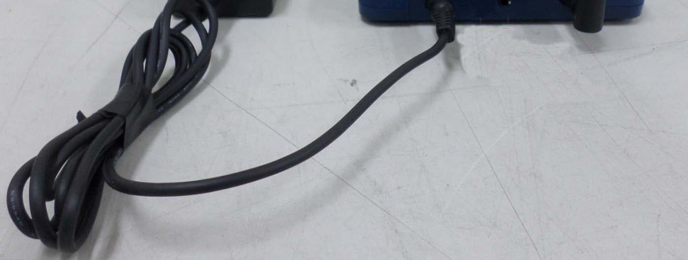
1. FRONT 2. REAR 3. PORT
Internal Photos
INTERNAL PHOTO 1. Main Board 1.1 Front 1.2 Rear 2. CDMA Module2. CDMA Module 2.1 Front 2.1 Front 3.Adapter3.Adapter 3.1 Front 3.2 Rear 4. Bluetooth 4.1 Front 4.1 Front
Operational Description
BlueMod+P24/G2 BlueMod+P25/G2 Hardware Reference Release r06 BlueMod+P24/G2 / BlueMod+P25/G2 Hardware Reference Release r06 www.stollmann.de Page 2 of 60 Note This product was developed for the purpose of communication. It is intended solely for our clients for integration into their own technical products after careful examination by experienced technical personnel for its suitability for the intended purpose. The product was not developed for or intended for use in any specific customer application. It may have to be adapted to the specific intended modalities of use or even replaced by other components in order to ensure flawless function in the respective areas of application. Performance data (range, power requirements, footprint, etc.) may depend on the operating environment, the area of application, the configuration, and method of control, as well as on other conditions of use; these may deviate from the technical specifications, the Design Guide specifications, or other product documentation. The actual performance characteristics can be determined only by measurements subsequent to integration in the target environment. Variations in the performance data of mass-produced devices may occur due to individual differences between such devices. Product samples were tested in a reference environment for compliance with the legal requirements applicable to the reference environment. No representation is made regarding the compliance with legal, regulatory, or other requirements in other environments. No representation can be made and no warranty can be assumed regarding the suitability of the product for a specific purpose. Stollmann reserves the right to make changes to the product without prior notice or to replace the product with a successor model. Of course, any changes to the product for which we have entered into a supply agreement with our customers will be made only if, and only to the extent that, such changes can reasonably be expected to be acceptable to our customers. No general commitment will be made regarding periods of availability; these must be subject to individual agreement. All agreements are subject to our Terms and Conditions for Deliveries and Payments, a copy of which is available from Stollmann. Trademarks The Bluetooth ® word mark and logos are owned by the Bluetooth SIG, Inc.. The NFC word mark and logos are owned by the NFC Forum. Any use of such marks by Stollmann E+V GmbH is under license. Other trademarks and trade names are those of their respective owners. BlueMod+P24/G2 / BlueMod+P25/G2 Hardware Reference Release r06 www.stollmann.de Page 3 of 60 Table of contents 1 Introduction ........................................................................................................ 6 1.1 Feature Summary ......................................................................................... 6 1.2 Applications .................................................................................................. 7 2 Block Diagram ................................................................................................... 7 3 Application Interface .......................................................................................... 8 3.1 Power Supply ................................................................................................ 8 3.1.1 Implementation in a Battery Power Host System ................................... 8 3.2 Power-up / -down slew-rate .......................................................................... 9 3.3 Optional Battery-Backup , ............................................................................... 9 3.4 Reset ............................................................................................................ 9 3.4.1 Pin State on reset ............................................................................... 11 3.5 Serial Interface ............................................................................................ 12 3.5.1 3-wire Serial Interface ......................................................................... 15 3.5.2 Implementing a Test and Firmware Update Interface .......................... 15 3.6 GPIO Interface ............................................................................................ 15 3.7 ADC ............................................................................................................ 16 3.8 DAC ............................................................................................................ 16 3.9 Bluetooth Radio Interface ............................................................................ 16 3.10 PCM Interface ............................................................................................. 16 3.11 USB Interface , ............................................................................................. 18 3.11.1 USB_DP, USB_DN ............................................................................. 18 3.11.2 USB Self-Powered Mode .................................................................... 18 3.11.3 USB Bus-Powered Mode .................................................................... 19 3.12 Serial Peripheral Interface ........................................................................... 20 3.13 I2C Interface ............................................................................................... 21 3.14 Operating in a Power-Switched Environment .............................................. 22 4 Pin Description................................................................................................. 24 4.1 Pin Numbering ............................................................................................ 24 4.2 Pin Description ............................................................................................ 25 4.2.1 General Pin Description ...................................................................... 25 BlueMod+P24/G2 /…
Text truncated - open the document above for the full version.
Test Report
Test Report for FCC Company name Address Telephone Product name Model No. Serial No. Test date Testing location H3G-650Manufacturer H3 SYSTEM Co., Ltd. NONECountry of origin 3F, 397-27, Doryong-dong, Yuseong-gu, Daejeon, R.O.Korea 82-42-862-9314 FCC ID: X59-H3G-650 21-Mar-12 ~ 26-Mar-12Date of issue27-Mar-12 Product CDMA Gateway H3 SYSTEM Co., Ltd. ESTF151203-008 KOREA ESTECH Co., Ltd. 58-1 OSan-Ri Kanam-Myon, Yeoju-Gun, KyungKi-Do, Korea 97-1, Hoeok-ri, Majang-myun, Ichion-city, Kyonggi-do, South Korea Report Number Applicant EST-QP-20-01(1)-(F15) Standard □ Class A ■ Class B Test resultOK □ Class A ■ Class B Test resultOK Tested by Reviewed by Abbreviation * Note (Signature) OK, Pass = Complied, Fail = Failed, N/A = not applicable Engineer J.H. KIM(Signature) - This test report is not permitted to copy partly without our permission - This test result is dependent on only equipment to be used - This test result based on a single evaluation of one sample of the above mentioned Test item ■ Conducted Emission ■ Radiated Emission Engineering Manager J.M.Yang FCC PART 15 (2010) , ANSI C 63.4 2003 Report Number : ESTF151203-008 , Web : www. estech. co. kr Page 1 of 57 Measurement facility registration number 94696 EST-QP-20-01(1)-(F15) 4 5 6 7 10 10 10 10 12 16 16 5. Carrier Frequency Separation ........................................................................... 5.2 Test instruments and measurement setup ...................................................... 5.3 Measurement results .................................................................................... Contents 1 1. Laboratory Information .................................................................................... 2. Descri ption of EUT .......................................................................................... 3. Test Standards ................................................................................................ 4. Measurement condition .................................................................................... 5.1 Test procedure .......................................................................................... 6.1 Test procedure.......................................................................................... 5.4 Trace data ................................................................................................... 6. Maximum Peak Output Power ........................................................................... EST-QP-20-01(1)-(F15) 16 16 17 17 17 17 18 20 20 20 20 21 23 8.5 Trace Data ................................................................................................ ... 8.2 Test instruments and measurement setup ...................................................... 8.4 Trace Data ................................................................................................... 6.1 Test procedure 6.2 Measurement results ................................................................................. ... 7.3 Measurement results .................................................................................... Report Number : ESTF151203-008 , Web : www. estech. co. kr Page 2 of 57 7. Number of Hopping Frequency ........................................................................... 7.1 Test procedure .......................................................................................... 7.2Test instruments and measurement setup ...................................................... 7.4 Trace data ................................................................................................ 8. Time of Occu pancy (Dwell Time) ........................................................................ 8.1 Test procedure .......................................................................................... 8.3 Measurement results .................................................................................... EST-QP-20-01(1)-(F15) 25 25 25 25 26 36 36 36 37 41 45 9.4 Trace data of band-edge & out of emission ................................................... 10. Measurement of radiated emission ............................................................... ... 10.5 Test data(bluetooth) ................................................................................. 10.1 Measurement equipment ........................................................................... 10.2 Environmental conditions ........................................................................... 9. Band-edge and Out of band emissions ............................................................ ... 9.1 Test procedure .......................................................................................... Contents 2 10.3 Test data(bluetooth) ................................................................................. 10.4 Restricted Band Edges .............................................................................. 9.2 Test instruments and measurement setu p ...................................................... 9.3 Measurement results of band-edge & out of emission ....................................... EST-QP-20-01(1)-(F15) 48 52 11.1 Measurement e quipment ...........................................................................52 11.2 Environmental conditions ........................................................................ ...52 53 54 54 55 56 57 Appendix 1. Special diagram Appendix 2. Antenna Requirement 11. Measurement of conducted emission ............................................................... ... 11.3 Test data ................................................................................................ 12.2. Setu p for Radiated Test :Above 1000 MHz ................................................... 12.3. Setup for Conducted Test : 0.15 ~ 30 MHz ................................................ Report Number : ESTF151203-008 , Web : www. estech. co. kr Page 3 of 57 10.6 Restricted Band Edges ...........…
Text truncated - open the document above for the full version.
Test Setup Photos
TEST SETUP PHOTOTEST SETUP PHOTO 1. Conducted emission setup photo 1.1 Front 1.2. Rear 2. Radiated Emission setup photo 2.1. Front 2.2. Rear 3. Radiated Emission setup photo (Above 1000 MHz) 3 1 Front 3.1 Front 3.2 Rear
Contact Information
Applicant
Sung-Dae Lim(Director)
Test Firm
ESTECH Co., Ltd.Yang Jinmo
Technical Specifications
| # | Rule Parts | Frequency Range | Power Output |
|---|---|---|---|
| 1 | 15C | 2.40 GHz - 2.48 GHz | 200.00 µW |
Other Applications from H3 SYSTEM Co., Ltd.
X59-H3G-800
May 18, 2015CDMA Gateway
Equipment Class
DSS - Part 15 Spread Spectrum Transmitter
X59-HRM-3200
Mar 23, 2015Heart Rate Monitor
Equipment Class
DTS - Digital Transmission System
X59-HRM-1000
Mar 19, 2012Heart Rate Monitor
Equipment Class
DTS - Digital Transmission System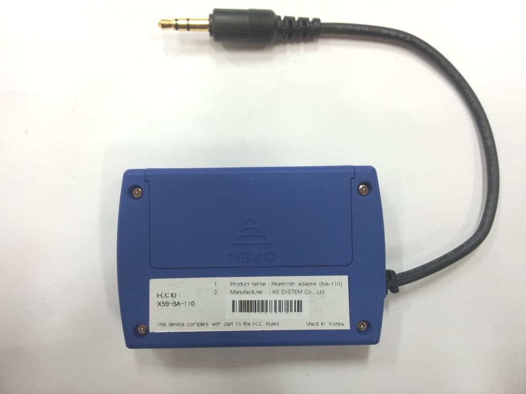
X59-BA-110
Dec 19, 2011Bluetooth Adapter
Equipment Class
DSS - Part 15 Spread Spectrum Transmitter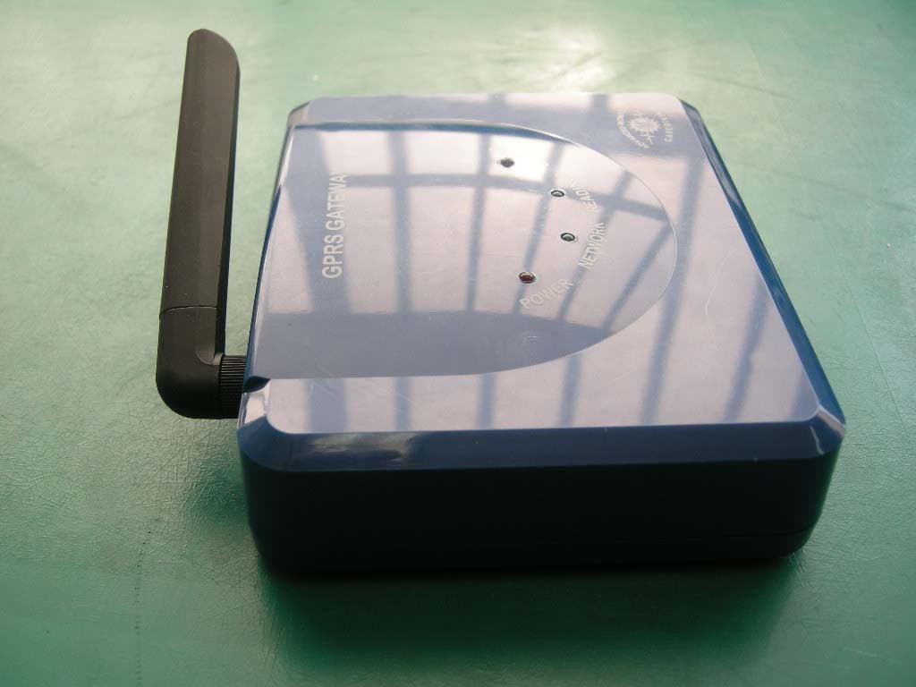
X59-H3G-700
Mar 10, 2011GSM/GPRS Gateway with Buuetooth
Equipment Class
DSS - Part 15 Spread Spectrum Transmitter