X59-H3G-700GSM/GPRS Gateway with Buuetooth
H3 SYSTEM Co., Ltd.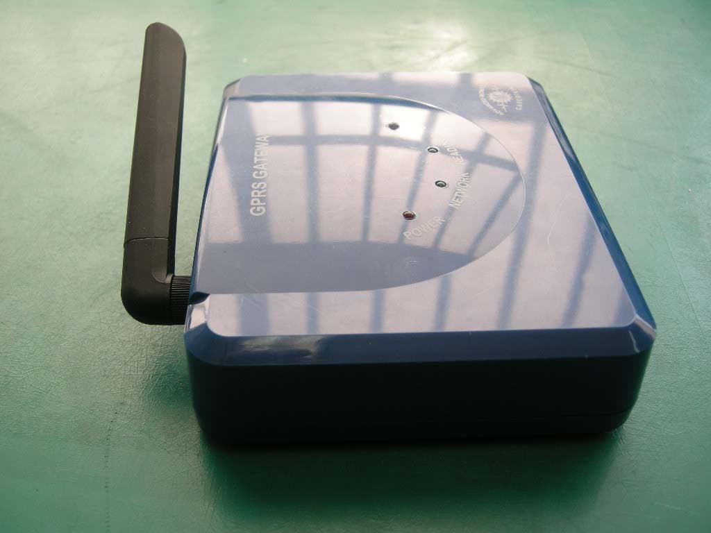
Click to zoom
Application Details
- Equipment Class
- DSS - Part 15 Spread Spectrum Transmitter
- Date of Grant
- Mar 10, 2011
- Application Purpose
- Original Equipment
- Date of Application
- Feb 23, 2011
- Equipment Note
- GSM/GPRS Gateway with Buuetooth
- Frequency Range
- 2402.00000000 - 2480.00000000
- Company
- H3 SYSTEM Co., Ltd.
- Country
- South Korea
Documents & Files
Document Text
Text extracted from the exhibit documents filed with the FCC. Open a document above to read the original.
Users Manual
GPRS Gateway Instruction H3 System Co., Ltd Print: 4th of Oct. 2010 Version: R0.9 Item: GSM/GPRS Gateway <Revision Note> No. Date Version Content Author 1 1 st OCT.2010 R0.8 Manho Kim, Jongbo Lee 2 4 th OCT.2010 R0.9 -Additional Content- 1. D/C SW Installation 2. Thermometer Pairing Manho Kim, Jongbo Lee 1. Gateway Installation 1) Unscrew and open the bottom cover. And insert a simcard. 2) To configure, connect a serial cable between a gateway and a PC and run the configuration software. And power on the gateway. ① Start command is transmitted from a gateway <Picture1: Simcard Insert> to configuration software. If there is any expected response from PC, communication for set-up mode is on. Otherwise, regular log is transmitted from the gateway to the configuration software. a. Check ‘setting’ in the configuration software: The set-up mode is activated and log is also transmitted to the configuration software. b. Uncheck ‘setting’ in the configuration software: Only log transmission is activated. 2. Pairing 1) Power off. 2) Select the pairing switch and power on. ① N: Normal mode (No pairing) ② P1: Pairing as a slave. Used for A&D weight scale. ③ P2: Pairing as a master. Used for IEM B/P monitor, J&J glucometer and ForaCare thermometer. <Picture3: Pairing Switch> * After pairing is done, it turns to normal operation mode. 2 ) LED ① On pairing, Reading LED in GREEN is on. ② At the success of pairing, Reading LED blinks GREEN two times. ③ At the failure of pairing, Reading LED blinks RED five times. 4) Device pairing method ① A&D weight scale: Select P1 and measure a weight with the device ② IEM B/P monitor: Select P2 and change into the pairing mode ③ J&J glucometer: Select P2 and change into the pairing mode ④ FORA thermometer: Select P2 and measure a temperature with the device 3. D/C Software Installation 1) Copy ‘DataCollection(GPRS)’ in the PC and run ‘GPRS_Server.exe’ file. <Picture4: DataCollection Server> 1) Description ① Port : Set the receiving socket port of DataCollection Server. ② Start: Start server ③ Stop: End server ④ Clear: Clear the log screen 2) Xml, log File ① Data and log folders are in DataCollection folder. ② Data : In data folder, xml file is created as folder by date, and in the xml file folder , the data is created by time. ③ Log: In log folder, log file is created as folder by date, and in the log file folder, the log file is created by time. ④ Ex) xml file name : 20101004194422_1111111111.xml -Creation logic of xml file name : Datetime + gateway Serial no ⑤ Ex) log file name : 20101004194422156.log -Creation logic of log file name : Datetime 4. Measurement & Data Transmission 1) After a measurement, the data is transmitted to the gateway by Bluetooth . And the data is automatically transmitted to the server via mobile networks. 2) Time set-up ① Gateway time set-up a. A gateway time set-up is done at the beginning of the server access. b. A gateway time set-up is done before disconnecting the server access. ② Device time set-up a. A&D weight scale, A&D thermometer, J&J Glucometer - Automatic time set-up is taken after sending data by Bluetooth. b. IEM B/P monitor: Time set-up should be done in the device manually. 3) Reading LED ① Starting Bluetooth communication: Reading GREEN led on ② End Bluetooth communication: Reading GREEN led off ③ At the success of Bluetooth communication: Reading LED blinks GREEN two times. ④ At the failure of Bluetooth communication: Reading LED blinks RED five times. 4) Data transmission to the server ① Sending LED a. Starting server communication : Sending LED in GREEN is on. b. End server communication: Sending LED in GREEN is off. c. At the success of server communication: Sending LED blinks GREEN two times. d. At the failure of server communication: Sending LED blinks RED five times. ② Notification: Server access is taken at power on and power off. ③ Heart beat: Server access is taken every six hours, after power-on. ④ At data receiving from device, automatic server access is taken and data is transmitted. ⑤ At the failure of server access, reconnection to the server is done periodically. Period is every hour. (Max. 3 times) 5. XLM File <?xml version="1.0" encoding="utf-8" ?> <Measure serial="1111111111" dc="0" battery="1.2"> <Device type="glucose"> <Data id="ZHZ306CBY" measuretime="20100101001250" result="103" unit="0" model="1" adapter="1" /> </Device> <Device type="glucose"> <Data id= "ZHZ306CBY" measuretime="20100101001406" result="112" unit="0" model="1" adapter="1" /> </Device> <Device type="pressure"> <Data id="61102DM2" measuretime="20100928084220" sys="139" dia="091" pul="094" /> </Device> <Device type="pressure"> <Data id="61102DM2" measuretime="20100928084337" sys="160" dia="088" pul="096" /> </Device> <Device type="weight"> <Data id="2008071403" measuretime= "20100101001716" result="066.90" unit="kg" battery="2.32" /> </Device> <Device type="glucose"> <Data id="ZHZ306CBY" measuretime="20100101001829" result="100" unit="0" model="1" adapter="1" /> </Device> <Device type="weight"> <Data id="2008071403" measuretime="20100101001957" result ="066.80" unit="kg" battery="2.32" /> </Device> <Device type="weight"> <Data id="2008071403" measuretime="20100101002342" result="066.80" unit="kg" battery="2.32" /> </Device> <Device type="thermometer"> <Data id="00123E0019B5" measuretime="20100101231100" otemp="98.42" btemp=”74.84” unit="F" /> </Device> </Measure> Item Description serial="1111111111" GateWay Serial No dc="0" Power Adapter Connection Status ( 0 : Connected ,1 : unconnected) battery="1.2" Gateway battery type="glucose" Device (glucose : Glucometer, pressure : Blood pressure monitor , weight : weight scale) id="ZHZ306CBY" Device Serial No Common measuretime="20100101001250" Measurement time result="103" Measurement value unit="0" Unit (0 : mg/dL, 1 : mmol/L) model="1" Glucometer Model (0:Ultra, 1:Ultra2, 2:Mini/Easy) Glucometer adapter="1" Glucometer Adapter (0 : N/A, 1: BA-100) sys="139" Systolic dia="091" Diastolic BP Mo…
Text truncated - open the document above for the full version.
Attestation Statements
FCC ID:X59-H3G-700 Attestation Statment H3 SYSTEM Co., Ltd. FCC ID:X59-H3G-700 Date: December 28 ,2010 15.247(a)(1) The hopping sequence must be pseudorandom all channels are used eually on average The receiver input bandwidth is approximately equall to the transmit bandwidth The receiver hops in sequence with the transmitted signal. 15.247(g) The system is designed to comply with all of the regulations in Section 15.247 When the transmitter is presented with a continuous data (or information) 15.247(h) The system does not coordinate its channel selection/hopping sequence with other Frequency hopping systems for the express purpose of avoiding the simultaneous Occupancy of individual hopping frequencies by multiple transmitters. Sincerely Jin Mo Yang, Engineering manager [email protected] TEL:82-31-631-8037 FAX:82-31-631-8039
Cover Letter(s)
H3 SYSTEM Co., Ltd. Date: December 28, 2010 Compliance Certification Services Certification Division 561F Monterey Road Morgan Hill, CA 95037 To whom it may concern: We, the undersigned, hereby authorize <ESTECH CO.,Ltd.>, to act on our behalf in all manners relating to application for equipment authorization, including signing of all documents relating to these matters. Any and all acts carried out by <ESTECH CO., Ltd.> on our behalf shall have the same effect as acts of our own. We, the undersigned, hereby certify that we are not subject to a denial of federal benefits, that includes FCC benefits, pursuant to Section 5301 of the Anti-Drug Abuse Act of 1988, 21 U.S.C. 853(a). In authorizing <ESTECH CO.,Ltd.> as our agent, we still recognize that we are responsible to: a) comply with the relevant provisions of the certification program; b) make all necessary arrangements for the conduct of the evaluation, including provision for examining documentation and access to all areas, records (including internal audit reports) and personnel for the purposes of evaluation (e.g. testing, inspection, assessment, surveillance, reassessment) and resolution of complaints; c) make claims regarding certification only in respect of the scope for which certification has been granted; d) do not use our product certification in such a manner as to bring the Certification Division into disrepute and not make any statement regarding our product certification which the Certification Division may consider misleading or unauthorized; e) upon suspension or cancellation of certification, discontinue use of all advertising matter that contains any reference thereto and return any certification documents as required by the Certification Division; f) use certification only to indicate the products are certified as being in conformity with specified standards; g) endeavor to ensure that no certificate or report nor any part thereof is used in a misleading manner; h) ensure that any reference to our product certification in communication media such as documents, brochures or advertising, complies with the requirements of the Certification Division; i) keep a record of all complaints made known to the us relating to the product’s compliance with requirements of the relevant standard and to make these records available to the Certification Division when requested; j) take appropriate action with respect to such complaints and any deficiencies found in products or services that affect compliance with the requirements for certification; k) document the actions taken. This authorization is valid until further written notice from the applicant. Sincerely Yours, Sign Kim, Young-Hwa / Senior engineer REMARK: 1. This authorization letter will be sent along with your application when filing with the Certification Division. 2. Please follow the format and type it on company letterhead and send original to us.
Cover Letter(s)
H3 SYSTEM Co., Ltd. 3F,397-27,Doryong-dong,Yuseong-gu,Daejeon, R.O.Korea TEL : 82-42-862-9314 FAX : 82-42-862-9315 Federal Communications Commission Authorization and Evaluation Division FCC ID : X59-H3G-700 Confidentiality Request Pursuant to Sections 0.457 and 0.459 of the Commission’s Rules, the Applicant hereby requests confidential treatment of information accompanying this Application as outlined below: Schematics Block Diagram The above materials contain trade secrets and proprietary information not customarily released to the public. The public disclosure of these matters might be harmful to the Applicant and provide unjustified benefits to its competitors. The Applicant understands that pursuant to Rule 0.457, disclosure of this Application and all accompanying documentation will not be made before the data of the Grant for this application. Sincerely, Sign Kim, Young-Hwa / Senior engineer
External Photos
Front Left side Rear side Right side Bottom side Port side
ID Label/Location Info
H3 SYSTEM Co., Ltd. GSM/GPRS Gateway MODEL : H3G-700 FCC ID:X59-H3G-700 This device complies with part 15 or rhe FCC Rules. Operation is subject to the dollowing two conditions : (1) This device may not cause harmful interference, and (2) this device must accept ant interference received, including interference that may cause undesired o peration.
Internal Photos
Internal Main 1 RF 1 Intenal 2 Intenal 3 Internal 4 Internal 4 Intenal 6 Internal 7 main -rear
Operational Description
Making machines talk. ® Makinigg gmnchameg Makinigg gmnchameg Makinigg gmnchameg EASE OF INTEGRATION BUSINESS SCALABLE QUALITY INVESTMENT PROTECTION The new GE865 product family introduces the smallest GSM/GPRS Ball-Grid-Array (BGA) modules in the market. The low profile and small size of the unique BGA package for the GE865-QUAD enable the design of extremely compact applications. Since connectors are eliminated, the solution cost is significantly reduced compared to conventional mounting. With its ultra-compact design and extended temperature range, the Telit GE865 product line is the perfect platform for high-volume m2m applications and mobile data devices. Additional features such as integrated TCP/IP protocol stack and serial multiplexer extend functionality of the application at no additional cost. The GE865 makes it possible to run the customer's application inside the module using Python Script Interpreter, thus making it the smallest, complete platform for m2m solutions. All Telit modules, support Over-the-Air firmware update by means Premium FOTA Management. By embedding RedBend’s vCurrent ® agent, a proven and battle-tested technology powering hundreds of millions of cellular handsets world-wide Telit is able to update its products by transmitting only a delta file, which represents the difference between one firmware version and another. As a part of Telit’s corporate policy of environmental protection, all products comply to the RoHS (Restriction of Hazardous Substances) directive of the European Union (EU Directive 2002/95/EG). GSM | GPRS GE865-QUAD Embedded Product features ■ Quad-band EGSM 850 / 900 / 1800 / 1900 MHz ■ GSM/GPRS protocol stack 3GPP Release 4 compliant ■ Output power - Class 4 (2W) @ 850 / 900 MHz - Class 1 (1W) @ 1800 / 1900 MHz ■ Control via AT commands according to 3GPP TS 27.005, 27.007 and Telit custom AT commands ■ Control via Remote AT commands ■ Power consumption (typical values) - Power off: ‹ 62 uA - Idle (registered, power saving): 1.5 mA @ DRX=9 - Dedicated mode: ‹ 240 mA @ max power level - GPRS cl.10: ‹ 420 mA @ max power level ■ Serial port multiplexer 3GPP TS 27.010 ■ SIM access profile ■ SIM application toolkit 3GPP TS 51.014 ■ Extended supply voltage range: 3.22 – 4.5 V DC (3.8 V DC nominal) ■ TCP/IP stack access via AT commands ■ Sensitivity: ‹ -107 dBm @ 850 / 900 MHz ‹ -106 dBm @ 1800 / 1900 MHz ■ Dimensions: 22 x 22 x 3 mm ■ Weight: 3.2 grams ■ Extended temperature range -40°C to +85°C (operational) -40°C to +85°C (storage temperature) ■ DARP/SAIC support ■ Enhanced Measurement Report support ■ RoHS compliant RUN AT Commands Remotely 5c Pfade Edit 5c Pfade 10mm Versatz Edit Serial Port Multi- plexer (3GPP 27.010) 5c Pfade 10mm Versatz Edit FOTA Premium FOTA Management Copyright © 2010, Telit · Subject to changes in technology, design and availability * Copyright © 1991–1995 by Stichting Mathematisch Centrum, Amsterdam, The Netherlands; All Rights Reser ved. Copyright © 1995–2001 Corporation for National Research Initiatives; All Rights Reser ved. Copyright © 2001–2010 Python Software Foundation; All Rights Reser ved. All Rights Reser ved are retained in Python. GSM | GPRS actual size GE865-QUAD Embedded Interfaces ■ 10 I/O ports maximum ■ Analog audio (balanced) ■ Digital Voice Interface ■ 2 A/D plus 1 D/A converter ■ Buzzer output ■ ITU-T V.24 serial link through CMOS UART: - Baud rate from 300 to 115.200 bps - Autobauding up to 115.200 bps Audio ■ Telephony, emergency call ■ Half rate, full rate, enhanced full rate and adaptive multi rate voice codecs (HR, FR, EFR, AMR) ■ Superior echo cancellation & noise reduction ■ Multiple audio profiles pre-programmed and fully configurable by mean AT commands ■ DTMF Approvals ■ Fully type approved conforming with R&TTE directive ■ CE, GCF, FCC, PTCRB, IC SMS ■ Point-to-point mobile originated and mobile terminated SMS ■ Concatenated SMS supported ■ SMS cell broadcast ■ Text and PDU mode ■ SMS over GPRS Circuit switched data transmission ■ Asynchronous non-transparent CSD up to 9.6 kbps ■ V.110 GPRS data ■ GPRS class 10 ■ Mobile station class B ■ Coding scheme 1 to 4 ■ PBCCH support ■ GERAN Feature Package 1 support (NACC, Extended TBF) GSM supplementary ■ Call forwarding ■ Call barring ■ Call waiting & call hold ■ Advice of charge ■ Calling line identification presentation (CLIP) ■ Calling line identification restriction (CLIR) ■ Unstructured supplementary services mobile originated data (USSD) ■ Closed user group Additional features ■ SIM phonebook ■ Fixed dialing number (FDN) ■ Real Time Clock ■ Alarm management ■ Network LED support ■ IRA , GSM, 8859-1 and UCS2 character sets ■ Jamming detection ■ Embedded TCP/IP stack, including TCP, IP, UDP, SMTP, ICMP and FTP protocols ■ Remote AT commands ■ Event monitor ■ PFM (Premium FOTA Management) Over-The-Air Update service Python* application resources ■ Python* script interpreter (module takes the application code directly in the Python* language) ■ Memory: 1.9 MB of NV memory for the user scripts and 1 MB RAM for the Python* engine usage Telit’s EASY features ■ EASY SCAN ® automatic scan over GSM frequencies (also without SIM card) Order-No. Please contact your Telit representative for order codes and all further information TheT e Tnw [10.2010] Distributed by: www.telit.com www.telit.com/techforum www.facebook.com/telitwireless www.twitter.com/telit_ws The n ww GwEn86hE5w The n ww GwEn86hE5w The n ww GwEn86hE5w Telit Wireless Solutions Inc. 3131 RDU Center Drive, Suite 135 Morrisville, NC 27560, USA Tel +1 888 846 9773 or +1 919 439 7977 Fax +1 888 846 9774 or +1 919 840 0337 E-Mail: [email protected] Telit Wireless Solutions Inc. Rua Cunha Gago, 700 - cj 81, Pinheiros São Paulo - SP, 05421001, Brazil Tel +55 11 2679 4654 Fax +55 11 2679 4654 E-Mail: [email protected] Telit Communications S.p.A. Via Stazione di Prosecco, 5/B I-34010 Sgonico (Trieste), Italy Tel +39 040 4192 200 Fax +39 040 4192 289 E-Mail: [email protected] Telit Wireles…
Text truncated - open the document above for the full version.
RF Exposure Info
RF Exposure Measurement 1. Introduction The maximum antenna Gain of the EUT is 3.5 dBi or 2.238 (numeric). 2. Classification MODE: PCS1900 3. RF Exposure Limit Magnetic Field Strength(A/m) Power Density (mW/cm 2 ) Average Time (minutes) 1.63 * (100) 6 4.89/f * (900/f 2 ) 6 0.1631.06 -f/3006 -56 Magnetic Field Strength(A/m) Power Density (mW/cm 2 ) Average Time (minutes) 1.63 * (100) 30 2.19/f * (180/f 2 ) 30 0.0730.230 -F/150030 -1.030 F = Frequency in MHz * = Plane-wave equivalent power density 30 - 300 300 - 1500 1500 - 100,000 61.4 1500 - 100,000- Frequency Range (MHz) Electric Field Strength (V/m) 0.3 - 1.34614 1.34 - 30824/f (B) Limits for General Population/Uncontrolled Exposure LIMITS FOR MAXIMUM PERMISSIBLE EXPOSURE (MPE) (A) Limits for Occupational/Controlled Exposures Frequency Range (MHz) Electric Field Strength (V/m) 3.0 - 301842/f 30 - 300 - - Because this deivce is transmitting the high power signal, it is regarded specially as a dangerous band for its heating harmfulness to the human body. The manufacturer whose product is working in this frequency band is obligatory to prove the harmfulness of his product. In this document, we try to prove the safety of radiation harmfulness to the human body for our product. The limit for Maximum Permissible Exposure (MPE) specified in FCC 1.1310 is followed. The Gain of the antenna used in this product is measured in a Fully Anechoic Chamber (FAC), and the maximum total power input to the antenna is measured. Through the Friis transmission formula and the maximum gain of the antenna, we can calculate the distance, away from the product, Page 1 of 3 The antenna of the product, under normal use condition, is at least 20cm away from the body of the user. Warning statement for keeping 20cm separation distance and the prohibition of operating next to a person has been printed on the user's manual. So, this product is classified as the Mobile Device. According to FCC 1.1310: The criteria listed in the following table shall be used to evaluate the environmental impact of human exposure to radio-frequency(RF) radiation as specified in 1.1307(b). LIMITS FOR MAXIMUM PERMISSIBLE EXPOSURE (MPE) - Class A 300 - 1500 27.5 - 0.3 - 3.0614 4. Friis Formula Friis transmission formula : P d = (P out *G) / (4*π*r 2 ) The maximum antenna Gain of the EUT is 3.5 dBi or 2.238 (numeric). P out = output power to antenna in mW G = gain of antenna in linear scale Pi = 3.1416 MODE: PCS1900 Page 2 of 3 The software provided by Manufacturer enabled the EUT to transmit with max power at lowest, middle and highest channel individually. Pd is the limit of MPE, 1mW/cm 2 . If we know the maximum Gain of the antenna and the total power input to the antenna, through the calculation, we will know the distance r where the MPE limit is reached. 5. Test Results 5.1 Antenna Gain The maximum antenna Gain of the EUT is 3.5 dBi or 2.238 (numeric). 5.2 Output Power into Antenna & Power Density(1 mW/cm 2 ): MODE: PCS1900 Channel Channel Frequency (MHz) Output Power to Antenna (mW) Power Density (mW/cm 2 ) Limit of Power Density (mW/cm 2 ) 5121852.20501.200.22331.0 6611880.00497.100.22141.0 8101909.80487.500.21721.0 Page 3 of 3
RF Exposure Info
RF Exposure Measurement 1. Introduction The maximum antenna Gain of the EUT is 2 dBi or 1.584 (numeric). 2. Classification MODE: GSM850 3. RF Exposure Limit Magnetic Field Strength(A/m) Power Density (mW/cm 2 ) Average Time (minutes) 1.63 * (100) 6 4.89/f * (900/f 2 ) 6 0.1631.06 -f/3006 -56 Magnetic Field Strength(A/m) Power Density (mW/cm 2 ) Average Time (minutes) 1.63 * (100) 30 2.19/f * (180/f 2 ) 30 0.0730.230 -F/150030 -1.030 F = Frequency in MHz * = Plane-wave equivalent power density 30 - 300 300 - 1500 1500 - 100,000 61.4 1500 - 100,000- Frequency Range (MHz) Electric Field Strength (V/m) 0.3 - 1.34614 1.34 - 30824/f (B) Limits for General Population/Uncontrolled Exposure LIMITS FOR MAXIMUM PERMISSIBLE EXPOSURE (MPE) (A) Limits for Occupational/Controlled Exposures Frequency Range (MHz) Electric Field Strength (V/m) 3.0 - 301842/f 30 - 300 - - Because this deivce is transmitting the high power signal, it is regarded specially as a dangerous band for its heating harmfulness to the human body. The manufacturer whose product is working in this frequency band is obligatory to prove the harmfulness of his product. In this document, we try to prove the safety of radiation harmfulness to the human body for our product. The limit for Maximum Permissible Exposure (MPE) specified in FCC 1.1310 is followed. The Gain of the antenna used in this product is measured in a Fully Anechoic Chamber (FAC), and the maximum total power input to the antenna is measured. Through the Friis transmission formula and the maximum gain of the antenna, we can calculate the distance, away from the product, Page 1 of 3 The antenna of the product, under normal use condition, is at least 20cm away from the body of the user. Warning statement for keeping 20cm separation distance and the prohibition of operating next to a person has been printed on the user's manual. So, this product is classified as the Mobile Device. According to FCC 1.1310: The criteria listed in the following table shall be used to evaluate the environmental impact of human exposure to radio-frequency(RF) radiation as specified in 1.1307(b). LIMITS FOR MAXIMUM PERMISSIBLE EXPOSURE (MPE) - Class A 300 - 1500 27.5 - 0.3 - 3.0614 4. Friis Formula Friis transmission formula : P d = (P out *G) / (4*π*r 2 ) The maximum antenna Gain of the EUT is 2 dBi or 1.584 (numeric). P out = output power to antenna in mW G = gain of antenna in linear scale Pi = 3.1416 MODE: GSM850 Page 2 of 3 The software provided by Manufacturer enabled the EUT to transmit with max power at lowest, middle and highest channel individually. Pd is the limit of MPE, 1mW/cm 2 . If we know the maximum Gain of the antenna and the total power input to the antenna, through the calculation, we will know the distance r where the MPE limit is reached. 5. Test Results 5.1 Antenna Gain The maximum antenna Gain of the EUT is 2 dBi or 1.584 (numeric). 5.2 Output Power into Antenna & Power Density(1 mW/cm 2 ): MODE: GSM850 Channel Channel Frequency (MHz) Output Power to Antenna (mW) Power Density (mW/cm 2 ) Limit of Power Density (mW/cm 2 ) 128824.202037.000.64221.0 190836.602296.100.72391.0 251848.802301.400.72561.0 Page 3 of 3
Test Report
Test Report for FCC Company name Address Telephone Product name Model No. Serial No. Test date Testing location Standard Tested by Reviewed by Abbreviation * Note - This test report is not permitted to copy partly without our permission - This test result is dependent on only equipment to be used - This test result based on a single evaluation of one sample of the above mentioned Report Number : ESTF151012-006 , Web : www. estech. co. kr Page 1 of 39 Report NumberESTF151012-006 Manufacturer Country of origin Applicant Product NONE H3 SYSTEM Co., Ltd. KOREA FCC ID:X59-H3G-700 OK, Pass = , Fail = Failed, N/A = not applicable Engineer J.H.KIM Engineering Manager J.M.Yang (Signature) (Signature) 23-Dec-10 H3 SYSTEM Co., Ltd. 3F,397-27,Doryong-dong,Yuseong-gu,Daejeon, R.O.Korea 82-42-862-9314 Measurement facility registration number 94696 ESTECH. Co., Ltd. 97-1 Hoiuk-Ri Majang-Myon, Icheon-city, KyungKi-Do, Korea FCC PART 15 2010 , ANSI C 63.4 2003 2010-12-22 GSM/GPRS Gateway H3G-700 Date of issue EST-QP-20-01(0)-(F15) 4 5 6 7 10 10 10 10 11 13 13 13 14 14 14 14 15 16 16 16 16 16 7.3 Measurement results ................................................................................. ... Report Number : ESTF151012-006 , Web : www. estech. co. kr Page 2 of 39 7. Number of Hopping Frequency ........................................................................... 7.1 Test procedure .......................................................................................... 7.2Test instruments and measurement setup ...................................................... 7.4 Trace data ....................................................................................... 8. Time of Occu pancy (Dwell Time) ........................................................................ 8.1 Test procedure .......................................................................................... 8.3 Measurement results .................................................................................... 4. Measurement condition .................................................................................... 8.2 Test instruments and measurement setup ...................................................... 8.4 Trace Data ................................................................................................... 5.1 Test procedure .......................................................................................... 6.1 Test procedure .......................................................................................... 6.2 Measurement results ............................................................ 5.4 Trace data ................................................................................................ ... 6. Maximum Peak Output Power ........................................................................... 5. Carrier Fre quency Separation ........................................................................... 5.2 Test instruments and measurement setup ...................................................... 5.3 Measurement results .................................................................................... Contents 1 1. Laboratory Information .................................................................................... 2. Descri ption of EUT .......................................................................................... 3. Test Standards ................................................................................................ EST-QP-20-01(0)-(F15) 19 19 19 19 20 25 25 25 26 30 34 11.1 Measurement equipment ........................................................................ 34 11.2 Environmental conditions ........................................................................ 34 35 36 36 37 38 39 Appendix 1. Spectral diagram Contents 2 12.4. Photographs of EUT.................................................................................... 10.3 Test data(bluetooth) ................................................................................. 10.4 Restricted Band Edges .............................................................................. 12. Photographs of test setup ........................................................................... 12.1.Setu p for Radiated Test : 30 ~ 1000 MHz ................................................... 9.2 Test instruments and measurement setu p ...................................................... 9.3 Measurement results of band-edge & out of emission ....................................... 9. Band-edge and Out of band emissions ............................................................... 9.1 Test procedure .......................................................................................... 10.1 Measurement equipment ........................................................................... 10.2 Environmental conditions ........................................................................... 9.4 Trace data of band-edge & out of emission ................................................... 10. Measurement of radiated emission ............................................................... ... Appendix 2. Antenna Requirement 11. Measurement of conducted emission ............................................................... ... 11.3 Test data ................................................................................................ 12.2. Setu p for Radiated Test :Above 1000 MHz ................................................... 12.3. Setup for Conducted Test : 0.15 ~ 30 MHz ................................................ Report Number : ESTF151012-006 , Web : www. estech. co. kr Page 3 of 39 EST-QP-20-01(0)-(F15) 1. Laboratory Information 1.1 General 1.2 Test Lab. Corporation Name : ESTECH Co., Ltd. Head Office : Rm 1015, World Venture Center II, 426-5, Gasan-dong, Geumcheon-gu, Seoul, Korea (Safety & Telecom. Test Lab) EMC Test Lab : 97-1, Hoeok-ri, Majang-myun, Ichi…
Text truncated - open the document above for the full version.
Test Setup Photos
TEST SETUP PHOTO 1. Conducted emission setup photo 1.1 Front 1.2. Rear 2. Radiated Emission setup photo 2.1. Front 2.2. Rear 2.3. Front (Above 1000MHz)
Contact Information
Applicant
Sung-Dae Lim(Director)
Technical Contact
Estech Co., LtdJin Mo Yasng
[email protected]+82 31 631 8039
97-1 Hoeok-Ri · Icheon City · South Korea
Test Firm
ESTECH Co., Ltd.Yang Jinmo
Technical Specifications
| # | Rule Parts | Frequency Range | Power Output |
|---|---|---|---|
| 1 | 15C | 2.40 GHz - 2.48 GHz | 900.00 µW |
Other Applications from H3 SYSTEM Co., Ltd.
X59-H3G-800
May 18, 2015CDMA Gateway
Equipment Class
DSS - Part 15 Spread Spectrum Transmitter
X59-HRM-3200
Mar 23, 2015Heart Rate Monitor
Equipment Class
DTS - Digital Transmission System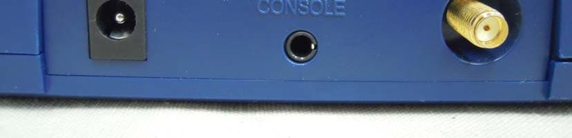
X59-H3G-650
Apr 15, 2012CDMA Gateway
Equipment Class
DSS - Part 15 Spread Spectrum Transmitter
X59-HRM-1000
Mar 19, 2012Heart Rate Monitor
Equipment Class
DTS - Digital Transmission System
X59-BA-110
Dec 19, 2011Bluetooth Adapter
Equipment Class
DSS - Part 15 Spread Spectrum Transmitter