X5NLBI-218Wireless ProController for WiiU
SHENZHEN XINGDASHINE ELECTRONICS CO., LTD.
Click to zoom
Application Details
- Equipment Class
- DSS - Part 15 Spread Spectrum Transmitter
- Date of Grant
- Jul 31, 2013
- Application Purpose
- Original Equipment
- Date of Application
- Jul 31, 2013
- Equipment Note
- Wireless ProController for WiiU
- Frequency Range
- 2402.00000000 - 2480.00000000
- Country
- China
Documents & Files
Document Text
Text extracted from the exhibit documents filed with the FCC. Open a document above to read the original.
Users Manual
Wireless Pro Controller For Wii U USER MANUAL Introduction: Thank you for purchasing the Wireless Pro Controller for Wii U. This product has been designed to enhance your gaming experience. To ensure the best performance of your product, please read this manual carefully and keep it for future reference. Should you have any difficulties using this product, please contact Customer Support. Warranty This product is guaranteed for a period of one year from the date of purchase. Please refer to the included warranty card for more details. Package Contents: • Wireless Pro Controller x 1 • USB - Mini USB Charging Cable x 1 • User Manual x 1 • Warranty Card x 1 L Button Left Analog Stick Channel LED Battery LED Right Analog Stick R Button D Pad -/Select Button HOME Button Power Button +/Start Button ZR Button Mini-USB Charging Socket ZL Button SYNC Button RESET Button Specifications: • Vibrant glow in both light and dark gaming situations • Designed for accessibility & extended gameplay comfort • Built-in rechargeable battery lasts for hours on single quick charge • Bluetooth wireless connection • Connect up to four Pro Controllers at one time for multiplayer action • Dual analog sticks and ergonomic button layout • Please note - Not compatible with original Wii system or games Charging Instructions: When the controller battery is low, the battery LED will glow RED. Please follow the steps below to charge the controller: • Connect the mini USB end of the charging cable to the charging mini USB socket of the controller (located on the top of the controller) • Connect the standard USB end of the charging cable to a USB port on the Wii U console, a USB port on a computer or a USB power adaptor • Charging will begin automatically (Please note, Wii U console or computer must be powered on to provide power for charging) o The battery LED will glow ORANGE when the battery is charging o The battery LED will turn off when the battery is fully charged Pairing Instructions: • Fully charge the Wireless Pro Controller (see Charging Instructions) • Power on the Wii U console and TV • Press the SYNC button on front of the Wii U console to display the controller pairing screen • Press the SYNC button on the back of the controller (all four channel LEDs will start blinking) o Channel LED will stop blinking and stay on the corresponding channel number when the controller successfully connects to the Wii U console Controller Glow: • Controller LED’s will glow BLUE when the controller is successfully connected to the console o Quickly press the power button to turn the button LED’s off o Quickly press the power button to turn the button LED’s on Resetting the Controller: Press the RESET button (located on the back of controller) if the following occurs: • Game crashes; or • Controller cannot sync to the console PRECAUTION AND MAINTENANCE Read, understand and follow all instructions, cautions and warnings listed in this manual and in the Wii U Operations Manual. Failure to follow instructions could result in personal injury or damage to the console. The controller must be used with care to avoid injury. The manufacturer will not be liable for injuries resulting from improper use of the controller. If you have any physical conditions, consult with a physician before using the controller. Stop using this product and consult a doctor if you or your children have any of the following symptoms: convulsions, loss of awareness, involuntary movement, eye or muscle twitching, altered vision and/or disorientation. Stop using this product immediately if you begin to feel tired or if you experience discomfort or pain in your hands and/or arms while playing your game. If the condition persists, consult a doctor. • Avoid prolonged use of this product. Take breaks every 30 minutes. • Route the charge cable so that it is not likely to be walked on or tripped over. Make sure the charge cable is not placed in positions or areas where it may become pinched or damaged. Do not wrap the charge cable around any part of the body. • Do not allow children to play with charge cable. • Do not use additional attachments other than those recommended or provided by the manufacturer unless otherwise specified. • Do not submerse the controller in water or expose the controller to heavy moisture. • Keep away from areas where dirt or liquid can get into the controller. • Do not operate the controller in or near water. • Do not operate the controller with wet hands. • Keep the controller away from direct sunlight and extreme temperatures. • Store the controller in an area away from dust and humidity. • Do not use the controller in any way other than its intended use. • Do not use the controller if damaged in any way. • Do not disassemble any part of the controller. • This product contains small parts that may cause choking if swallowed. Not intended for use by children under 3 years of age. • Use a dry cloth to clean the controller; never use chemicals. This device complies with Part 15 of the FCC Rules. Operation is subject to the following two conditions: (1) this device may not cause harmful interference, and (2) this device must accept any interference received, including interference that may cause undesired operation. Changes or modifications not expressly approved by the party responsible for compliance could void the user's authority to operate the equipment. NOTE: This equipment has been tested and found to comply with the limits for a Class B digital device, pursuant to Part 15 of the FCC Rules. These limits are designed to provide reasonable protection against harmful interference in a residential installation. This equipment generates, uses and can radiate radio frequency energy and, if not installed and used in accordance with the instructions, may cause harmful interference to radio communications. However, there is no guarantee that interference will not occur in a particular installation. If this equipment does cause harmful interfere…
Text truncated - open the document above for the full version.
Cover Letter(s)
SCS-F18: Project and Product Certification Representative Authorization Letter Page 1 of 2 Rev 3.0 775 Montague Expressway Milpitas, CA 95035 Tel: 408-526-1188 Fax: 408-526-1088 Email: [email protected] Project and Product Certification Representative Authorization Letter Revision History Reason for Amendment (current / obsolete) From To Approved Date Initial Release (obsolete) 1.0 1.0 Nov-14-2006 Revised wording (obsolete) 1.0 2.0 Sept–25-2007 Updated company template (current) 2.0 3.0 Jan-31-2012 SCS-F18: Project and Product Certification Representative Authorization Letter Page 2 of 2 Rev 3.0 SHENZHEN XINGDASHINE ELECTRONICS CO., LTD. 2013-7-27 To: SIEMIC, INC. 775 Montague Expressway, Milpitas, CA 95035 USA Dear Sir/Madam, Re: Project and Product Certification Representative Authorization Letter We, SHENZHEN XINGDASHINE ELECTRONICS CO., LTD. hereby authorize SIEMIC, INC. to act as a Certification Body for certifying for the following project(s): FCC ID: X5NLBI-218 (Wireless ProController for WiiU MODEL No.: LBI-218) We affirm that between SIEMIC and SHENZHEN XINGDASHINE ELECTRONICS CO., LTD., any difference in understanding, including test plan, measurement methods, applicable standards and relevant procedures and processes have been resolved prior to commencement of testing activities. Sincerely, July Zheng/ Sales E-mail: [email protected] Phone: +86-755 33800723 Fax: +86-755 33800724 Address: D3 East Xintang Industrial Zone, Baishixia, Fuyong, Shenzhen, China
Cover Letter(s)
Confidentiality Request Letter SHENZHEN XINGDASHINE ELECTRONICS CO., LTD. 2013-7-27 To: Federal Communications Commission Office of Engineering and Technology Equipment Authorization Division 7345 Oakland Mills Road Columbia, Maryland 21046 Subject: Permanent Confidentiality Request for FCC ID: X5NLBI-218 We hereby request confidential treatment of information accompanying this application as outlined below: - Block diagram - Operation description - Schematic The above materials contain trade secrets and proprietary information not customarily released to the public. The public disclosure of these materials may be harmful to the applicant and provide unjustified benefits to its competitors. The applicant understands that pursuant to Section 0.457 & 0.459 of the Rules, disclosure of this application and all accompanying documentation will not be made before the date of the Grant for this application. July Zheng/ Sales E-mail: [email protected] Phone: +86-755 33800723 Fax: +86-755 33800724 Address: D3 East Xintang Industrial Zone, Baishixia, Fuyong, Shenzhen, China
ID Label/Location Info
Label Location
ID Label/Location Info
ID Label Wireless ProController for WiiU FCC ID: X5NLBI-218 Model Number: LBI-218 Made in China This device complies with Part 15 of the FCC Rules. Operation is subject to the following two conditions: (1) this device may not cause harmful interference, and (2) this device must accept any interference received, including interference that may cause undesired operation.
Internal Photos
BT Module Antenna
RF Exposure Info
FCC ID: X5NLBI-218 Portable device According to §15.247(e)(i) and §1.1307(b)(1), systems operating under the provisions of this section shall be operated in a manner that ensures that the public is not exposed to radio frequency energy level in excess of the Commission’s guidelines. According to KDB447498 D01 General RF Exposure Guidance V05 The 1-g and 10-g SAR test exclusion thresholds for 100 MHz to 6 GHz at test separation distances ≤ 50 mm are determined by: [(max. power of channel, including tune-up tolerance, mW)/(min. test separation distance, mm)] * [√f(GHz)] ≤ 3.0 for 1-g SAR and ≤ 7.5 for 10-g extremity SAR, where f(GHz) is the RF channel transmit frequency in GHz; Power and distance are rounded to the nearest mW and mm before calculation; The result is rounded to one decimal place for comparison; The test exclusions are applicable only when the minimum test separation distance is ≤ 50 mm and for transmission frequencies between 100 MHz and 6 GHz. When the minimum test separation distance is < 5 mm, a distance of 5 mm is applied to determine SAR test exclusion. We use 5mm as separation distance to calculate. Maximum measured transmitter power: Transmit Frequency (GHz) Max Conducted Power (dBm) Result calculation 1-g SAR 2.480 8.54 2.25 3.0 Conclusion: For the max result 2.25≤ 3.0 for 1-g SAR extremity SAR, No SAR is required.
Test Report
TRF No:FCC 15.247/A Page 1 of 50 Report No: ES130705029E Shenzhen EMTEK Co.,Ltd. Building 69, Majialong Industry Zone, Nanshan District, Shenzhen,Guangdong,China www.emtek.com.cn Tel: +86-755-2695 4280 Fax: +86-755-2695 4282 Access to the World ELECTROMAGNETIC EMISSIONS COMPLIANCE REPORT INTENTIONAL RADIATOR CERTIFICATION TO FCC PART 15 SUBPARTC REQUIREMENT OF Wireless ProController for WiiU MODEL No.: LBI-218 FCC ID: X5NLBI-218 Trademark: N/A REPORT NO: ES130705029E ISSUE DATE: July 22, 2013 Prepared for SHENZHEN XINGDASHINE ELECTRONICS CO., LTD. D3 East Xintang Industrial Zone, Baishixia, Fuyong, Shenzhen, China Prepared by SHENZHEN EMTEK CO., LTD Bldg 69, Majialong Industry Zone, Nanshan District, Shenzhen, Guangdong, China TEL: 86-755-26954280 FAX: 86-755-26954282 TRF No:FCC 15.247/A Page 2 of 50 Report No: ES130705029E Shenzhen EMTEK Co.,Ltd. Building 69, Majialong Industry Zone, Nanshan District, Shenzhen,Guangdong,China www.emtek.com.cn Tel: +86-755-2695 4280 Fax: +86-755-2695 4282 Access to the World VERIFICATION OF COMPLIANCE Applicant: SHENZHEN XINGDASHINE ELECTRONICS CO., LTD. D3 East Xintang Industrial Zone, Baishixia, Fuyong, Shenzhen, China Manufacturer: SHENZHEN XINGDASHINE ELECTRONICS CO., LTD. D3 East Xintang Industrial Zone, Baishixia, Fuyong, Shenzhen, China Product Description: Wireless ProController for WiiU Model Number: LBI-218 Serial Number: N/A File Number: ES130705029E We hereby certify that: The above equipment was tested by SHENZHEN EMTEK CO., LTD. The test data, data evaluation, test procedures, and equipment configurations shown in this report were made in accordance with the procedures given in ANSI C63.4 (2009) and the energy emitted by the sample EUT tested as described in this report is in compliance with conducted and radiated emission limits of FCC Rules Part 15.247. The test results of this report relate only to the tested sample identified in this report. Date of Test : July 6, 2013 to July 18, 2013 Prepared by : Joe Xia/Editor Reviewer : June Xie/Supervisor Approve & Authorized Signer : Lisa Wang/Manager TRF No:FCC 15.247/A Page 3 of 50 Report No: ES130705029E Shenzhen EMTEK Co.,Ltd. Building 69, Majialong Industry Zone, Nanshan District, Shenzhen,Guangdong,China www.emtek.com.cn Tel: +86-755-2695 4280 Fax: +86-755-2695 4282 Access to the World Ta b l e o f C o n t e n t s 1. GENERAL INFORMATION ................................................................................................. 5 1.1 PRODUCT DESCRIPTION........................................................................................................................... 5 1.2 RELATED SUBMITTAL(S) / GRANT (S) ..................................................................................................... 5 1.3 TEST METHODOLOGY.............................................................................................................................. 5 1.4 SPECIAL ACCESSORIES............................................................................................................................ 5 1.5 EQUIPMENT MODIFICATIONS.................................................................................................................. 5 1.6 TEST FACILITY........................................................................................................................................ 6 2. SYSTEM TEST CONFIGURATION .................................................................................... 7 2.1 EUT CONFIGURATION............................................................................................................................. 7 2.2 EUT EXERCISE........................................................................................................................................ 7 2.3 TEST PROCEDURE.................................................................................................................................... 7 2.4 LIMITATION............................................................................................................................................. 7 2.5 CONFIGURATION OF TESTED SYSTEM................................................................................................... 10 2.6 EQUIPMENT USED IN TESTED SYSTEM.................................................................................................. 10 2.7 DESCRIPTION OF TEST MODES............................................................................................................... 11 3. SUMMARY OF TEST RESULTS ....................................................................................... 12 4. CONDUCTED EMISSIONS TEST ..................................................................................... 13 4.1 MEASUREMENT PROCEDURE:................................................................................................................ 13 4.2 TEST SET-UP (BLOCK DIAGRAM OF CONFIGURATION) ....................................................................... 13 4.3 MEASUREMENT EQUIPMENT USED: ...................................................................................................... 13 4.4 CONDUCTED EMISSION LIMIT.................................................................................................................. 13 4.5 MEASUREMENT RESULT:....................................................................................................................... 13 5. RADIATED EMISSION TEST ............................................................................................ 14 5.1 MEASUREMENT PROCEDURE................................................................................................................. 14 5.2 TEST SET-UP (BLOCK DIAGRAM OF CONFIGURATION) ....................................................................... 15 5.3 MEASUREMENT EQUIPMENT USED: ...................................................................................................... 16 5.4 MEASUREMENT RESULT.......…
Text truncated - open the document above for the full version.
Contact Information
Applicant
July Zheng(Sales)
Test Firm
EMTEK (Shenzhen) Co., Ltd.David Lee
Technical Specifications
| # | Rule Parts | Frequency Range | Power Output |
|---|---|---|---|
| 1 | 15C | 2.40 GHz - 2.48 GHz | 7.10 mW |
Other Applications from SHENZHEN XINGDASHINE ELECTRONICS CO., LTD.

X5NLBI-315
Dec 15, 2015Wireless Remote
Equipment Class
DSS - Part 15 Spread Spectrum Transmitter
X5NLBI-170
Oct 13, 2010WII 2in1 remote
Equipment Class
DXX - Part 15 Low Power Communication Device Transmitter
X5NLBP-054
Mar 04, 2010Bluetooth headset
Equipment Class
DXT - Part 15 Low Power Transceiver, Rx Verified
X5NLBP-024
Feb 07, 2010PS3 wireless controller
Equipment Class
DXX - Part 15 Low Power Communication Device Transmitter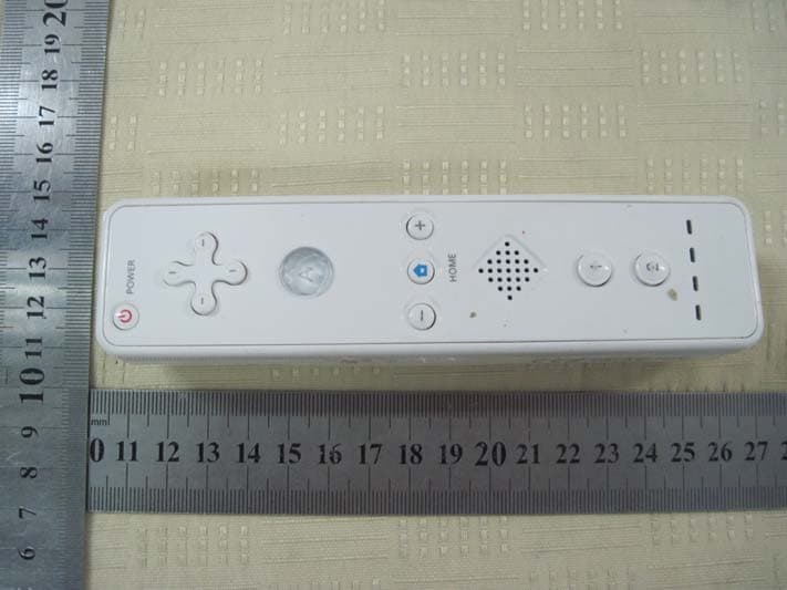
X5NLBI-023
Feb 03, 2010Wii Remote
Equipment Class
DXX - Part 15 Low Power Communication Device Transmitter