X7DWL0149Wireless USB Adapter
ZIONCOM ELECTRONICS (SHENZHEN) LTD.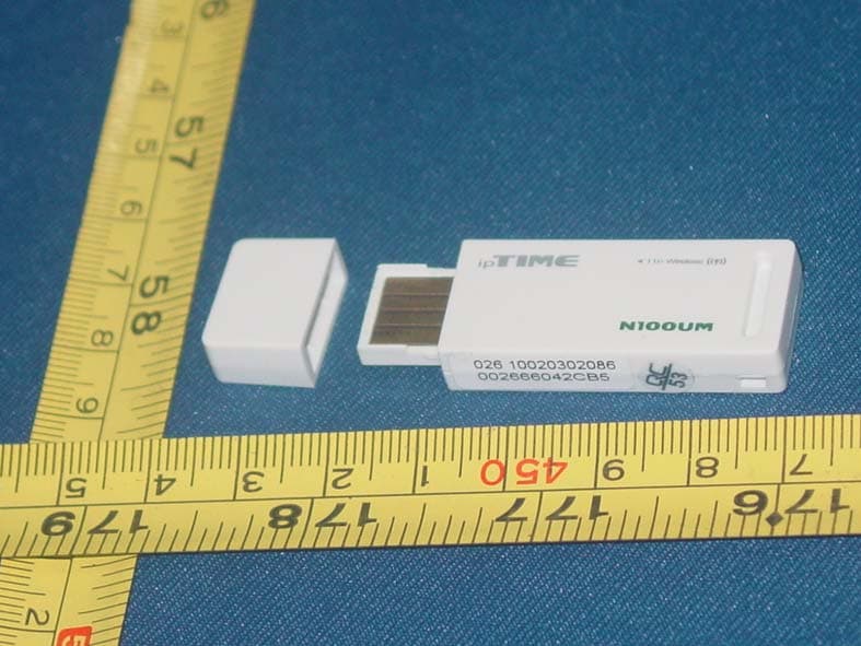
Click to zoom
Application Details
- Equipment Class
- DTS - Digital Transmission System
- Date of Grant
- May 11, 2010
- Application Purpose
- Original Equipment
- Date of Application
- May 10, 2010
- Equipment Note
- Wireless USB Adapter
- Frequency Range
- 2422.00000000 - 2452.00000000
- Country
- China
Documents & Files
Document Text
Text extracted from the exhibit documents filed with the FCC. Open a document above to read the original.
Users Manual
Quick Installation Guide US300EX Lite II Wireless N USB Adapter CONTENTS English........................................................................................................................................... ............1-1 French........................................................................................................................................................2-1 Portuguese................................................................................................................................................ 3-1 Spanish...................................................................................................................................................... 4-1 Quick Installation Guide US300EX Lite II Wireless N USB Adapter US300EX LiteII 1-1 The Quick Installation Guide will help you to install US300EX Lite II in your computer, including basic hardware and software installation, as well as configuration of wireless network availability. A. Hardware Installation There are two ways to install the Adapter: 1. Plug the Adapter directly to the USB port on your computer. 2. Connect the adapter and your computer through the USB cable attached in package. The LED will light up when the Adapter is installed successfully and the PC is on. B. Software Installation 1. Insert the Resource CD into your CD-ROM drive, and open the folder with the same name as your product. Then double-click Setup.exe in the proper folder according to your operating system to start the installation, Figure 1 will appear. 2. Follow the step-by-step instructions following in the continued prompted screens to complete InstallShield Wizard steps. Note: 1) If Windows XP warns about Windows Logo testing, click Continue Anyway to continue the installation. 2) After the Installation, or will appear at the bottom of the screen in your system tray. Otherwise, there may be some problems about the installation, please check it seriously. C. Configure wireless connection in Windows XP with MSI Wireless Client Utility The Adapter's tray icon shows the signal strength using color and the received signal strength indication (RSSI). If the icon is (green), a wireless connection has been established. If the icon is (black), there is no connection. Follow the steps below to launch a wireless connection manually. 1. Double click the icon , then the Wireless Utility will appear, you can also run the utility by clicking Startĺ ProgramĺRalink wirelessĺRalink Wireless Utility. On the prompted configuration tab page,click the Profile Management, and you will see the next screen (Figure 2). US300EX LiteII 1-2 Figure 2. 2. Click Scan on the screen above, and you will see a new screen (shown in Figure 3), click Refresh, then the latest available Network will appear. Figure 3 3. In the screen above, highlight a network name and click Activate, then you will see the next screen (shown in Figure 4). Enter the Client Name and SSID, and you can connect to the network. Figure 4 Note: If a well-balanced wireless network cannot be created, please refer to the User Guide on the Resource CD or your dealer for help. D. Configure wireless connection in Windows XP with Windows XP Wireless Zero Configuration 1. To use Windows XP Wireless Zero Configuration, select OptionĺSelect Client Software... on the menu of Utility shown in Figure 5. US300EX LiteII 1-3 Figure 5 3. Right-click the icon “ ”, and then select View Available Wireless Networks in the next screen (Figure 6). Figure 6 4. Then, Figure 7 will appear with many available wireless network choices. You can highlight a network and then click Connect to add to a network. Note: If you have not installed SP2 for Windows XP, the screens below will not be available. Figure 7 5. If the connection is finished, the icon will display like the next screen shown. US300EX LiteII 1-4 Figure 8 Note: If a well-balanced wireless network cannot be created, please ask your dealer for help. E. WPS configuration WPS function allows the Adapter to join a wireless network quickly. If the wireless card supports Wi-Fi Protected Setup (WPS), you can establish a wireless connection between wireless card and router using either Push Button Configuration (PBC) method or PIN method. Here we will introduce two ways to configure the WPS (For the configuration of WPS, here takes the Wireless Router of our company for example. For more ways of WPS Configuration. 1. PBC (Push Button Configuration) method 1) Press the WPS button on the rear panel of the Router and released immediately. Figure 9 Figure 10 Once the ‘figure 10’ image shown, choose the router name, above is ‘RG300EX LITE’ for example. Press US300EX Lite II WPS button, the dongle would connect to router immediately, you could find the USB wifi card mac in the router connection page(figure10). 2. PIN method 1) Double click icon, Figure 10 would shows up, you would see the Pin code from the right bar. 2) get pin code from the right colume. 3) input the PIN code to following page to US300EX LiteII 1-5 Figure 11 4) Go to wireless configuration, you would find the adapter information as following. Figure12 COPYRIGHT & TRADEMARKS Specifications are subject to change without notice. MSI is a registered trademark of Micro Star International Co., Ltd. Other brands and product names are trademarks or registered trademarks of their respective holders. No part of the specifications may be reproduced in any form or by any meansor used to make any derivative such as translation, transformation, or adaptation without permission from Micro Star International Co., Ltd. Copyright © 2006-2010 Micro-Star Int'l Co., Ltd. All rights reserved. US300EX LiteII 1-6 FCC Caution : Changes or modifications not expressly approved by the party responsible for compliance could void the user's authority to operate the equipment. Compliance statement: 1: This device is verified to comply with Part 15 of the FCC Rules. Operation subject to the following two condit…
Text truncated - open the document above for the full version.
Attestation Statements
Attestation for FCC Declaration of Conformity FCC ID: X7DIP0494 Data: Mar. 20, 2010 Please be notified that we,the undersigned, ZIONCOM TECHNOLOGY LIMITED declares that the product which bears the above FCC ID is also compliant with the FCC requirements for Doc,The test report number supporting the DoC is 1002270,Testing in regards to this report was done by SIEMIC Inc, located at 2206 Ringwood Avenue,San Jose,CA 95131 USA which has been accredited in accordance to all of the requirements of 47CFR2.948(d)and(e)of the FCC rules and KDB349827 Sincerely, Tony Geng / Maneger ZIONCOM TECHNOLOGY LIMITED Tel: +86-755-61363299 Fax: +86-755-61363322 Email: [email protected]
External Photos
Label Location
ID Label/Location Info
Label Location 34.5mm 9.5mm 40x20mm 1.4mm 18.5mm 2.8mm 4mm
Internal Photos
Antenna Location
RF Exposure Info
RF Exposure Statement 1. Standard Applicable According to 1.1307 (b)(1), systems operating under the provisions of this section shall be operated in a manner that ensure that the public is not exposed to radio frequency energy level in excess of the Commission’s guideline. This is a portable device. 2. Measurement Result: This is a portable device and the max average output power is 10.06 dBm (10.0641mW). The antenna gain of the device is 2dBi The EIRP of the device is 10.06+2=12.06dBm=16.0694mW Lower than the low threshold 60/f GHz = (24.37 mW),. The SAR/MPE measurement is not necessary.
Test Report
FCC ID: X7DWL0149 NS Technology Co., Ltd. Report No. NSE-F10044653 Page 1 of 110 FCC COMPLIANCE REPORT for ZIONCOM TECHNOLOGY LIMITED Wireless USB Adapter Model Number: WL0149; US300EX Lite Prepared for : ZIONCOM TECHNOLOGY LIMITED Address : Building A1~A2,lantian Science and Technology Park,Xinyu Road Xinqiao Henggang Block Shajing Street,Baoan District, Shenzhen City Prepared By : NS Technology Co., Ltd. Address : Chenwu Industrial Zone, Houjie Town, Dongguan City, Guangdong, China Tel: +86-769-85935656 Fax: +86-769-85991080 Report Number : NSE-F10044653 Date of Test : Mar. 10~Mar . 28, 2010 Date of Report : Mar. 30, 2010 FCC ID: X7DWL0149 NS Technology Co., Ltd. Report No. NSE-F10044653 Page 2 of 110 TABLE OF CONTENTS Test Report Declaration Page 1. GENERAL PRODUCT INFORMATION ......................................................................... 4 1.1. Product Function ........................................................................................................................ 4 1.2. Description of Device (EUT) .....................................................................................................4 1.3. Difference between Model Numbers ......................................................................................... 4 1.4. Independent Operation Modes ................................................................................................... 4 1.5. Test Supporting System ............................................................................................................. 5 2. TEST SITES.......................................................................................................................... 6 2.1. Test Facilities ............................................................................................................................. 6 2.2. List of Test and Measurement Instruments ................................................................................ 7 3. TEST SET-UP AND OPERATION MODES .................................................................... 8 3.1. Principle of Configuration Selection.......................................................................................... 8 3.2. Block Diagram of Test Set-up....................................................................................................8 3.3. Test Operation Mode and Test Software.................................................................................... 8 3.4. Special Accessories and Auxiliary Equipment .......................................................................... 8 3.5. Countermeasures to Achieve EMC Compliance........................................................................ 8 4. TEST SUMMARY................................................................................................................ 9 5. DATA RATE VS POWER................................................................................................. 10 6. EMISSION TEST RESULTS............................................................................................ 11 6.1. Conducted Emission at The Mains Terminals Test.................................................................. 11 6.2. Radiated Emission.................................................................................................................... 14 6.3. 6dB Bandwidth ........................................................................................................................ 70 6.4. Power Spectral Density Test ....................................................................................................73 6.5. Output Power Test.................................................................................................................... 76 6.6. Band Edge ................................................................................................................................ 77 6.7. ANTENNA REQUIREMENT ............................................................................................... 110 FCC ID: X7DWL0149 NS Technology Co., Ltd. Report No. NSE-F10044653 Page 3 of 110 NS Technology Co., Ltd. Applicant: Address: ZIONCOM TECHNOLOGY LIMITED Building A1~A2,lantian Science and Technology Park,Xinyu Road Xinqiao Henggang Block Shajing Street,Baoan District, Shenzhen City Manufacturer: Address: ZIONCOM TECHNOLOGY LIMITED Building A1~A2,lantian Science and Technology Park,Xinyu Road Xinqiao Henggang Block Shajing Street,Baoan District, Shenzhen City E.U.T: Wireless USB Adapter Model Number: WL0149; US300EX Lite Trade Name: ------ Operating Frequency: IEEE802.11b 2412~2462MHz; IEEE802.11g 2412~2462MHz IEEE802.11n HT20:2412~2462MHz;IEEE802.11n HT40:2422~2452MHz Date of Receipt: Mar.4, 2010 Date of Test: Mar. 10~Mar . 28, 2010 Test Specification: FCC Part 15 Subpart C: Oct. 2009 ANSI C63.4:2003 Test Result: The equipment under test was found to be compliance with the requirements of the standards applied. Issue Date: Mar.30, 2010 Tested by: Reviewed by: Approved by: Jade/ Engineer Iceman Hu / Supervisor Steven Lee / Manager Other Aspects: None. Abbreviations: OK/P=passed fail/F=failed n.a/N=not applicable E.U.T=equipment under tested This test report is based on a single evaluation of one sample of above mentioned products ,It is not permitted to be duplicated in extracts without written approval of NS Technology Co., Ltd. FCC ID: X7DWL0149 NS Technology Co., Ltd. Report No. NSE-F10044653 Page 4 of 110 1. GENERAL PRODUCT INFORMATION 1.1. Product Function Details please refer to Technical Construction Form and User Manual. 1.2. Description of Device (EUT) E.U.T. : Wireless USB Adapter Model No. : WL0149 Operating Frequency : 2412~2462MHz Number of Channels : IEEE 802.11b/g,802.11n HT20:11 Channels IEEE 802.11n HT40:7 Channels Type of Modulation : DSSS for IEEE 802.11b, OFDM for IEEE 802.11g and IEEE 802.11n IEEE 802.11b:11/5.5/2/1M bps IEEE 802.11g:54/48/36/24/18/12/9/6Mbps IEEE 802.11n HT20:130/117/104/78/65/58.5/…
Text truncated - open the document above for the full version.
Test Report
FCC ID: X7DWL0149 NS Technology Co., Ltd. Report No. NSE-F10044653 Page 70 of 110 6.3. 6dB Bandwidth 6.3.1. Test limits >500kHz. 6.3.2. Test procedure 1. The EUT was placed on a table which is 0.8m above ground plane. 2. Connect EUT RF output port to the spectrum analyzer through an RF attenuator. 3. Set SA Center Frequency = Operation frequency, RBW=100kHz,VBW=300kHz. 4. Set SA trace max hold, then view. 6.3.3. Test result Pass Test Channel Frequency MHz 6dB bandwidth MHz Conclusion 802.11b CH1 2412MHz 12.0 Pass 802.11b CH6 2437MHz 12.0 Pass 802.11b CH11 2462MHz 11.8 Pass 802.11g CH1 2412MHz 17.2 Pass 802.11g CH6 2437MHz 17.2 Pass 802.11g CH11 2462MHz 17.2 Pass 802.11n HT20 CH1 2412MHz 17.4 Pass 802.11 n HT20 CH6 2437MHz 17.4 Pass 802.11 n HT20 CH11 2462MHz 17.4 Pass 802.11 n HT20 CH1 2422MHz 36.2 Pass 802.11 n HT20 CH4 2437MHz 36.4 Pass 802.11 n HT20 CH7 2452MHz 36.4 Pass When IEEE 802.11b’s data rate was 11Mbps ; IEEE 802.11g’s data rate was 54Mbps, When IEEE 802.11n HT20’s data rate was 130Mbps ; IEEE 802.11n HT40’s data rate was 135Mbps the EUT have maximum output power and all the test was performed in this data rate set. The test plots as following: FCC ID: X7DWL0149 NS Technology Co., Ltd. Report No. NSE-F10044653 Page 71 of 110 802.11b CH1 2412MHz 802.11g CH1 2412MHz 802.11b CH6 2437MHz 802.11g CH6 2437MHz 802.11b CH11 2462MHz 802.11g CH11 2462MHz FCC ID: X7DWL0149 NS Technology Co., Ltd. Report No. NSE-F10044653 Page 72 of 110 802.11n HT20 CH1 2412MHz 802.11n HT40 CH1 2422MHz 802.11 n HT20 CH6 2437MHz 802.11 n HT40 CH4 2437MHz 802.11 n HT20 CH11 2462MHz 802.11 n HT40 CH7 2452MHz FCC ID: X7DWL0149 NS Technology Co., Ltd. Report No. NSE-F10044653 Page 73 of 110 6.4. Power Spectral Density Test 6.4.1.Test procedure 1. The EUT was placed on a table which is 0.8m above ground plane. 2. Connect EUT RF output port to the spectrum analyzer through an RF attenuator. 3. Set SA Center Frequency = Operation frequency, RBW=3kHz,VBW=300kHz. 4. Set SA trace max hold, then view. 6.4.2. Test result Pass Test Channel Read (dBm) Cable loss (dB) Result (dBm) Limit 802.11b CH1 -18.57 3 -15.57 8.0 802.11b CH6 -20.07 3 -17.07 8.0 802.11b CH11 -14.90 3 -11.90 8.0 802.11g CH1 -18.84 3 -15.84 8.0 802.11g CH6 -20.22 3 -17.22 8.0 802.11g CH11 -15.01 3 -12.01 8.0 802.11n HT20 CH1 -18.94 3 -15.94 8.0 802.11 n HT20 CH6 -20.32 3 -17.32 8.0 802.11 n HT20 CH11 -15.12 3 -12.12 8.0 802.11 n HT40 CH1 -23.85 3 -20.85 8.0 802.11 n HT40 CH4 -25.89 3 -22.89 8.0 802.11 n HT40 CH7 -26.57 3 -23.57 8.0 Note:Result=Read+cable loss Factor=antenna gain(2dB)+cable loss(3dB) The test plots as following: When IEEE 802.11b’s data rate was 11Mbps ; IEEE 802.11g’s data rate was 54Mbps, When IEEE 802.11n HT20’s data rate was 130Mbps ; IEEE 802.11n HT40’s data rate was 135Mbps the EUT have maximum output power and all the test was performed in this data rate set. FCC ID: X7DWL0149 NS Technology Co., Ltd. Report No. NSE-F10044653 Page 74 of 110 802.11b CH1 2412MHz 802.11g CH11 2412MHz 802.11b CH6 2437MHz 802.11g CH11 2437MHz 802.11b CH11 2462MHz 802.11g CH11 2462MHz FCC ID: X7DWL0149 NS Technology Co., Ltd. Report No. NSE-F10044653 Page 75 of 110 802.11n HT20 CH1 2412MHz 802.11n HT40 CH1 2422MHz 802.11n HT20 CH6 2437MHz 802.11n HT40 CH4 2437MHz 802.11n HT20 CH11 2462MHz 802.11n HT40 CH7 2452MHz FCC ID: X7DWL0149 NS Technology Co., Ltd. Report No. NSE-F10044653 Page 76 of 110 6.5. Output Power Test 6.5.1. Test procedure 1. The EUT was placed on a table which is 0.8m above ground plane. 2. Connect EUT RF output port to the Power meter through an RF attenuator. 6.5.2. Test result Pass Test Channel Read (dBm) Cable loss (dB) Result (dBm) Limit 802.11b CH1 7.03 3 10.03 30.00 802.11b CH6 7.06 3 10.06 30.00 802.11b CH11 6.97 3 9.97 30.00 802.11g CH1 6.87 3 9.87 30.00 802.11g CH6 7.05 3 10.05 30.00 802.11g CH11 6.76 3 9.76 30.00 802.11n HT20 CH1 5.96 3 8.96 30.00 802.11 n HT20 CH6 6.18 3 9.18 30.00 802.11n HT20 CH11 5.97 3 8.97 30.00 802.11 n HT40 CH1 5.25 3 8.25 30.00 802.11 n HT40 CH4 5.21 3 8.21 30.00 802.11 n HT40 CH7 5.08 3 8.08 30.00 Note:Result=Read+cable loss Factor=antenna gain(2dB)+cable loss(3dB) When 802.11b’s data rate was 11MHz;802.11g’s data rate was 54MHz;the EUT have Maximum output and all the test was performed in this data rate set. FCC ID: X7DWL0149 NS Technology Co., Ltd. Report No. NSE-F10044653 Page 77 of 110 6.6. Band Edge 6.6.1. Test limits According to §15.247(c), in any 100 kHz bandwidth outside the frequency bands in which the spread spectrum intentional radiator in operating, the radio frequency power that is produced by the intentional radiator shall be at least 20dB below that in the 100kHz bandwidth within the band that contains the highest level of the desired power, In addition, radiated emissions which fall in the restricted bands, as defined in §15.205(a), must also comply with the radiated emission limits specified in15.209(a). 6.6.2. Test procedure 1. The EUT is placed on a turntable, which is 0.8m above the ground plane and worked at highest radiated power. 2. The turntable was rotated for 360 degrees to determine the position of maximum emission level. 3. EUT is set 3m away from the receiving antenna, which is varied from 1m to 4m to find out the highest emission. 4. Set the spectrum analyzer in the following setting in order to capture the Lower and upperband-edges of the emission: (a) PEAK: RBW=VBW=1MHz / Sweep=AUTO (b) AVERAGE: RBW=1MHz / VBW=10Hz / Sweep=AUTO The EUT was tested in Chamber Site. 6.6.3. Test result PASS. The test plots as following: FCC ID: X7DWL0149 NS Technology Co., Ltd. Report No. NSE-F10044653 Page 78 of 110 FCC ID: X7DWL0149 NS Technology Co., Ltd. Report No. NSE-F10044653 Page 79 of 110 FCC ID: X7DWL0149 NS Technology Co., Ltd. Report No. NSE-F10044653 Page 80 of 110 FCC ID: X7DWL0149 NS Technology Co., Ltd. Report No. NSE-F10044653 Page 81 of 110 FCC ID: X7DWL0149 NS Technology Co., Ltd. Report No. NSE-F10044653 Page 82 of 110 FCC ID: X7DWL0149 NS Technology Co., Ltd. Report …
Text truncated - open the document above for the full version.
Test Setup Photos
1.1. Set-up for conducted emission at the mains terminals test 1.2. Set-up for radiated emission test(30MHz~1000MHz) 1.3. Set-up for radiated emission test(above 1GHz) 1.4. Set-up for Peak output Power Test
Contact Information
Applicant
Carmen Lee(Product Manager)
Technical Contact
NS Technology Co., Ltd.Iceman Hu
[email protected]86 769 85935656
Chenwu Industrial Zone, Houjie Town, · Dongguan, Guangdong · China
Test Firm
Bureau Veritas Shenzhen Co., Ltd. Dongguan BranchAlec Hu
Technical Specifications
| # | Rule Parts | Frequency Range | Power Output |
|---|---|---|---|
| 2 | 15C | 2.42 GHz - 2.45 GHz | 7.00 mW |
Other Applications from ZIONCOM ELECTRONICS (SHENZHEN) LTD.

X7D-WX029
Jul 25, 2021300Mbps Wireless N Range Extender
Equipment Class
DTS - Digital Transmission System
X7D-IP04227
Dec 16, 2014AC1200 Wireless Dual Band Gigabit Router
Equipment Class
NII - Unlicensed National Information Infrastructure TX
X7D-IP04268
Dec 16, 2014AC1200 Long Range Wireless Dual Band Router
Equipment Class
NII - Unlicensed National Information Infrastructure TX
X7D-IP04213
Nov 26, 2014300Mbps Wireless N Router
Equipment Class
DTS - Digital Transmission System
X7D-WL0273
Nov 23, 2014AC600 Wireless Dual Band USB Adapter
Equipment Class
NII - Unlicensed National Information Infrastructure TX