X9P20100326RECEIVER - USB DONGLE
Shenzhen Paoluy Silicone Technology Co., Ltd.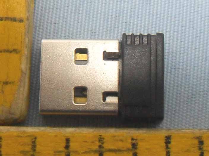
Click to zoom
Application Details
- Equipment Class
- JBP - Part 15 Class B Computing Device Peripheral
- Date of Grant
- Mar 31, 2010
- Application Purpose
- Original Equipment
- Date of Application
- Mar 31, 2010
- Equipment Note
- RECEIVER - USB DONGLE
- Country
- China
Documents & Files
Document Text
Text extracted from the exhibit documents filed with the FCC. Open a document above to read the original.
Users Manual
2.4G Wireless Silicone Keyboard User’s Guide Thank you for purchasing our wireless keyboard. Please read this user manual before operation. Package Contents ● Wireless Silicone Keyboard. ● A copy of user manual. Product Specifications 1. Ultra slim and portable design: our Silicone keyboard’s flat design offers an easy typing surface. . 2. The keyboard features soft touch keys to reduce loud and disruptive typing noise 3. The silicon wrap is dust and water proof to ensure long life. 4. Our keyboard functions in extreme temperatures (-20°C to 55°C) and humidity levels (20%-50%). 5. Built-in 2.4 GHz frequency wireless transmission provided to extend operating distance and reduce interference. 6. Energy-saving design enables efficient use of batteries; estimated over one year for normal, daily use conditions. Specification Parameters Receiver USB2.0 connection. Operating distance up to 10 meters Work voltage: 2.2 – 3.3V Working current: <5mA Standby current :<1mA Dormancy current;<100uA Dimensions: length 412mm*width 218mm* height 15mm System Requirements Computer operating system requirements: Works with Windows 98, ME, 2000, XP, Vista. Operation Guide Install to Computer: Step 1. Insert Batteries (1) Open the Battery Cabinet as below. Receiver cell Low-voltage matching light, Figures 1 and 2 Inserts two AAA batteries into battery storage Synch button (2). Inset two AAA alkaline batteries. (Please refer to the diagram, figure 1 above for the polarity of batteries). Close the Battery Cabinet cover. Step 2. Connecting the Keyboard to the Dongle Take out the Mini receiver from the cell on the bottom of the keyboard and then insert it into computer’s USB connector, then synch the receiver by pressing the button (shown in diagram, figure 2). You can now use your keyboard! Attentions: 1. This product should not come in contact with sharp objects. 2. Do not place heavy objects on the keyboard. 3. Keep the keyboard away for heat or hot objects. 4. Do not pull nor twist the keyboard; it should be gently rolled up for storage. 5. Do not use oil or organic materials like acetone and Toulon, on keyboard 6. Do not press on keyboard after it is rolled. 7. The silicon surface can be cleaned with water, alcohol, disinfected. Trouble Shooting Keyboard cannot connect with computer: 1. Make sure the dongle is connected to the USB port. 2. Make sure that the keyboard is within the effective range---10M. 3. Please kindly check the batteries. If they are short of power, replace them with new ones 4. Resynch the keyboard Prompt: When your battery voltage is lower than 2.0V, the red led light will signal into a flashing mode. You need to replace battery in order to avoid effect operation of the keyboard. Federal Communication Commission Interference Statement This equipment has been tested and found to comply with the limits for a Class B digital device. Pursuant to Part 15 of the FCC Rules. These limits are designed to provide reasonable protection against harmful interference in a residential installation. This equipment generates uses and can radiate radio frequency energy and, if no installed and used in accordance with the instructions, may cause harmful interference to radio or television reception, which can be determined by turning the equipment off and on, the user is encouraged to try to correct the interference by one of the following measures: • Reorient or relocate the receiving antenna • Increase the separation between the equipment and receiver. • Connect the equipment into an outlet on a circuit different from that to which the receiver is connected • Consult the dealer or an experienced radio/TV technician for help. This device complies with Part 15 of the FCC Rules. Operation is subject to the following two conditions: (1) this device may not cause harmful interference, and (2) this device must accept any interference received, including interference that may cause undesired operation. FCC Caution: Any change or modifications no expressly approved by the party responsible for compliance could void the user’s authority to operate this equipment. When disposing old batteries, please follow local regulations for disposal. Never throw away old batteries in as normal trash.
Block Diagram
MCU Crystal Frequency: 12MHz RF Crystal Frequency: 12MHz ANTENNA RF (SE9713) E 2 PROM MCU (SE98DB) USB Port
External Photos
Page 17 o f 19 FCC ID: X9P20100326 Anbotek Compliance Laboratory Limited Report No. 201003688F-1 Figure 1 The EUT-Front View Figure 2 The EUT-Back View
ID Label/Location Info
FCC ID Label Sample for FCC ID: X9P20100326
ID Label/Location Info
The proposed Label Location on EUT Proposed FCC ID Label Location Proposed Label Location on EUT The EUT-Side View/Proposed FCC ID Label Location
Internal Photos
Page 18 o f 19 FCC ID: X9P20100326 Anbotek Compliance Laboratory Limited Report No. 201003688F-1 Figure 3 The EUT-Inside View Figure 4 PCB of the EUT-Front View Page 19 o f 19 FCC ID: X9P20100326 Anbotek Compliance Laboratory Limited Report No. 201003688F-1 Figure 5 PCB of the EUT-Back View
Operational Description
APPLICANT: Shenzhen Paoluy Silicone Technology Co., Ltd. FCC ID: X9P20100326 The theory of Dongle BL-WKB107: 1. MCU & RF module: responsible for communication with Transmitter(Keyboard) and PC. 2. MCU crystal frequency is 12MHz. 3. RF module crystal frequency is 12MHz. 4. Power circuit: to provide steady power to around circuit via USB port. 5. The antenna of equipment is on the PCB. 6. The antenna gain is 0dBi.
Schematics
1 2 34 ABCD 4 3 2 1 D CBA C6104 3V3 IIC_SDAIIC_SCL 3V3 EEPROM C6 EE PRO M SCL 1 GND 2 SDA 3 WP 5 VCC 4 U2SE24C02TB(TSOT-23-5) GND Y112M C3 24pF(12pF) C4 30pF(15pF) C2104 C1104 +5V D+ 3 D- 2 VCC 1 GND 4 5 J1 USB +5V C510uF S1ID KEY ID_KEY D-D+ L1 Bead 3V3 OSCI OSCO C2 3V3 C1 +5V R11 3.3R R9 33R R10 33R C16104 R9 R10 R11 L1 D- 1 P92 2 P93 3 P52 4 P53 5 P54 6 P55 7 P56 8 P57 9 P60 10 P61 11 P62 12 P65 13 P66 14 VDD 15 OSCI 16 OSCO 17 VSS 18 V3.3 19 D+ 20 U1 SE95CQ(QFN-20) SE95CD(DICE) RF LED1+5V NumLockD- D+ 3V3 GND OSCO OSCI SPI_MISORF_RST ID_KEYIIC_SDA SPI_CLK RF_CS PKT_FLAG IIC_SCL C710uF +1.8V +1.8V +1.8V C140.1uF C152.2UF C130.1uF C1210NF SPI_MISORF_RSTSPI_CLKSPI_MOSIRF_CSPKT_FLAGC80.1uF C90.1uF ANT PLL_VDD 2 VCO_VDD 3 ANT 4 GND 5 RF_VDD 6 IF_VDD 7 AMS_VDD 8 GND 12 PKT_FLAG 11 RXCLK 10 FIFO_FLAG 9 DIG_VDD 13 SPI_SS 14 SPI_MOSI 15 SPI_CLK 16 RESET_n 17 SPI_MISO 18 VDD_IO 19 LDO_VOUT 20 CKPHA 21 GND 22 VDD_IN 23 XTALO 24 XTALI 1 U3 R8713(QFN-24) 87 13(DICE) C1110nF CF1* L2* 3V3 OSCI C102.2nF R3 3.3R RF R3 CF2* V2.3 GiGa HiD 2.4G USB RX GiGa HiD-V2-SE-RX-PP TitleSize A4 Date:File: Number Sheet of Drawn By: Revision C3 la yer +1.8V CAPLock E2_WP E2_WP Y1 2*6 3*8 49 S : 12 MHZ±10 PPM, 20 pF C4 30 PF,C3 24 P C3 La ye r Y1 32 25 : 12 MHZ±10 PPM, 12 pF C4 15 PF,C3 12 PF C3 La ye r SPI_MOSI
Test Report
Page 1 o f 19 FCC ID: X9P20100326 Anbotek Compliance Laboratory Limited Report No. 201003688F-1 FCC TEST REPORT FOR Shenzhen Paoluy Silicone Technology Co., Ltd. Dongle Model No.: BL-WKB107 Prepared for : Shenzhen Paoluy Silicone Technology Co., Ltd. Address : No.31, furong road, gushu village, xixiang town, bao’an district, shenzhen Tel: (86) 755-33819221 Fax: (86) 755-33676866 Prepared By : Anbotek Compliance Laboratory Limited Address : 2F, Langfeng Building, Kefa Road North, Hi-tech Industrial Park, Nanshan District, Shenzhen 518057, China Tel: (86) 755-26014771 Fax: (86) 755-26014772 Report Number : 201003688F-1 Date of Test : Mar. 16~25, 2010 Date of Report : Mar. 26, 2010 Page 2 o f 19 FCC ID: X9P20100326 Anbotek Compliance Laboratory Limited Report No. 201003688F-1 TABLE OF CONTENTS Description Page Test Report Verification 1. GENERAL INFORMATION ............................................................................................................... 4 1.1. Description of Device (EUT) ..........................................................................................................................4 1.2. Description of Test Facility.............................................................................................................................5 1.3. Measurement Uncertainty ...............................................................................................................................5 2. POWER LINE CONDUCTED MEASUREMENT ............................................................................ 6 2.1. Test Equipment ...............................................................................................................................................6 2.2. Block Diagram of Test Setup ..........................................................................................................................6 2.3. Power Line Conducted Emission Measurement Limits (FCC Part 15 Class B) .............................................6 2.4. Configuration of EUT on Measurement..........................................................................................................7 2.5. Operating Condition of EUT...........................................................................................................................7 2.6. Test Procedure.................................................................................................................................................7 2.7. Power Line Conducted Emission Measurement Results.................................................................................7 3. RADIATED EMISSION MEASUREMENT..................................................................................... 10 3.1. Test Equipment .............................................................................................................................................10 3.2. Block Diagram of Test Setup ........................................................................................................................10 3.3. Radiated Emission Limit (Subpart B Class B) ..............................................................................................11 3.4. EUT Configuration on Measurement ............................................................................................................11 3.5. Operating Condition of EUT.........................................................................................................................11 3.6. Test Procedure...............................................................................................................................................11 3.7. Radiated Emission Measurement Results .....................................................................................................12 4. PHOTOGRAPH ................................................................................................................................... 15 4.1. Photo of Power Line Conducted Emission Test............................................................................................15 4.2. Photo of Radiated Emission Test ..................................................................................................................15 APPENDIX I (Photos of EUT) (3 Pages) Page 3 o f 19 FCC ID: X9P20100326 Anbotek Compliance Laboratory Limited Report No. 201003688F-1 TEST REPORT Applicant Shenzhen Paoluy Silicone Technology Co., Ltd. Manufacturer Shenzhen Paoluy Silicone Technology Co., Ltd. EUT Dongle (A) MODEL NO. : BL-WKB107 (B) SERIAL NO. : N/A (C) POWER SUPPLY: DC 5V via USB Port (D) TRADE MARK: N/A Measurement Procedure Used: FCC Rules and Regulations Part 15 Subpart B 15.107&15.109-2007 & ANSI C63.4-2003 The device described above is tested by Anbotek Compliance Laboratory Limited To determine the maximum emission levels emanating from the device. The maximum emission levels are compared to the FCC Part 15 Subpart B Class B limits both radiated and conducted emissions. The measurement results are contained in this test report and Anbotek Compliance Laboratory Limited Is assumed full responsibility for the accuracy and completeness of these measurements. Also, this report shows that the Equipment Under Test (EUT) is to be technically compliant with the FCC requirements. This report applies to above tested sample only. This report shall not be reproduced in part without written approval of Anbotek Compliance Laboratory Limited Date of Test : Mar. 16~25, 2010 Prepared by : (Engineer) Reviewer : (Project Manager) Approved & Authorized Signer : (Manager) Page 4 o f 19 FCC ID: X9P20100326 Anbotek Compliance Laboratory Limited Report No. 201003688F-1 1. GENERAL INFORMATION 1.1. Description of Device (EUT) Description : Dongle Model Number : BL-WKB107 Test Power Supply : AC 120V, 60Hz Antenna Gain : 0dBi Notebook PC : Manufacturer: IBM M/N: 2373 S/N: 99-OL5HH CE , FCC: DOC Applicant : Shenzhen Paoluy Silicone Technology Co., Ltd. Ad…
Text truncated - open the document above for the full version.
Test Setup Photos
Page 15 o f 19 FCC ID: X9P20100326 Anbotek Compliance Laboratory Limited Report No. 201003688F-1 4. PHOTOGRAPH 4.1. Photo of Power Line Conducted Emission Test 4.2. Photo of Radiated Emission Test
Contact Information
Applicant
Xiaogang Yang(Quality Director)
Test Firm
Anbotek Compliance Laboratory limitedDaniel Zhu
Technical Specifications
| # | Rule Parts | Frequency Range | Power Output |
|---|---|---|---|
| 1 | 15B | - | - |
Other Applications from Shenzhen Paoluy Silicone Technology Co., Ltd.

X9PKB6031
Sep 16, 2015Bluetooth Keyboard
Equipment Class
DSS - Part 15 Spread Spectrum Transmitter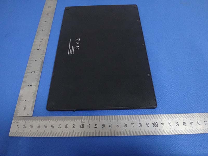
X9PKB6026
Oct 26, 2014Solar Bluetooth Keyboard
Equipment Class
DSS - Part 15 Spread Spectrum Transmitter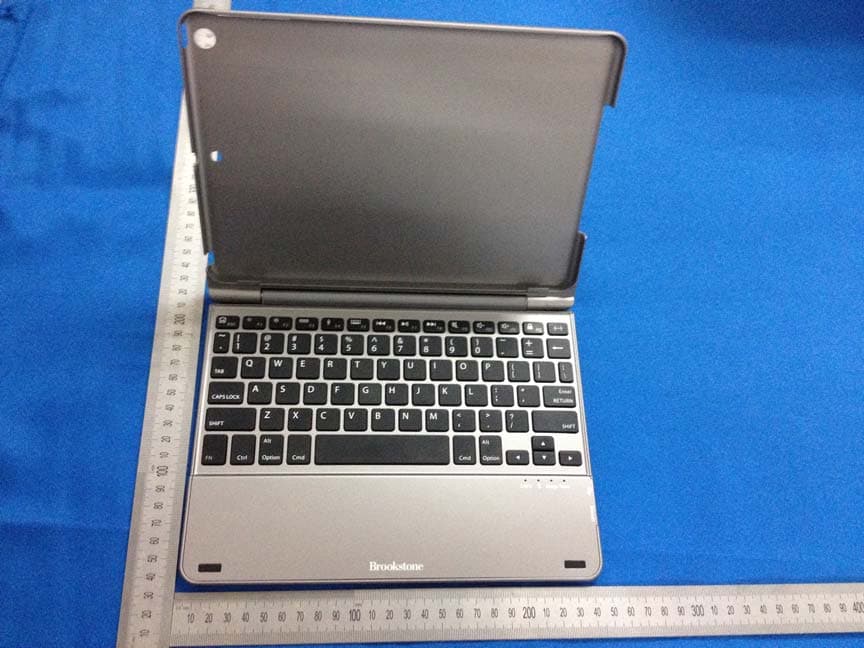
X9PKB6013I
May 27, 2014Bluetooth Keyboard
Equipment Class
DSS - Part 15 Spread Spectrum Transmitter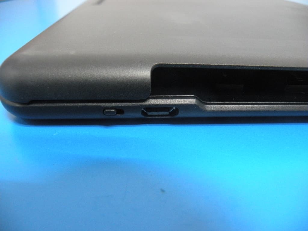
X9PKB6012I
Aug 04, 2013BLUETOOTH KEYBOARD
Equipment Class
DSS - Part 15 Spread Spectrum Transmitter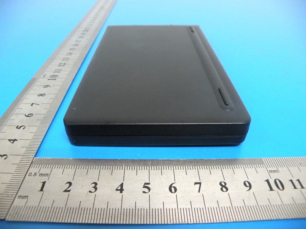
X9PKB6007I
Aug 04, 2013BLUETOOTH KEYBOARD
Equipment Class
DSS - Part 15 Spread Spectrum Transmitter