XBADSB09104Home Energy Meter
Aeon Labs LLC.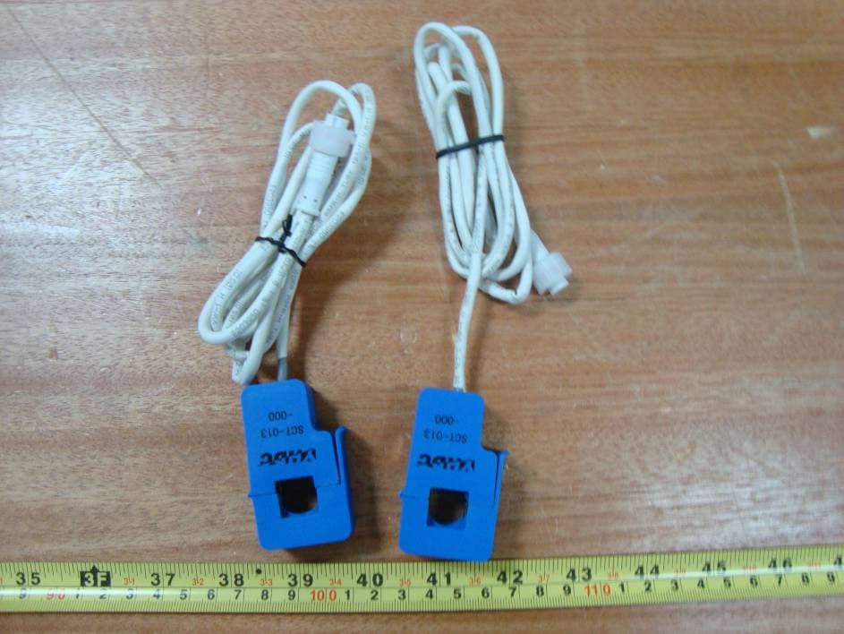
Click to zoom
Application Details
- Equipment Class
- DXX - Part 15 Low Power Communication Device Transmitter
- Date of Grant
- May 10, 2010
- Application Purpose
- Original Equipment
- Date of Application
- May 10, 2010
- Equipment Note
- Home Energy Meter
- Frequency Range
- 908.40000000 - 908.42000000
- Company
- Aeon Labs LLC.
- Country
- United States
Documents & Files
Document Text
Text extracted from the exhibit documents filed with the FCC. Open a document above to read the original.
Users Manual
Aeon Labs Home Energy Meter (Z-Wave Home Energy Meter) Accessory : : : C C C U U U R R R R R R E E E N N N T T T T T T R R R A A A N N N S S S F F F O O O R R R M M M A A A T T T O O O R R R Introduction: The Aeon Labs Home Energy Meter is a low-cost energy meter for the entire home. It can wirelessly report immediate wattage and kWh usage of the AC mains to a Z- Wave gateway. By taking advantage of the Z-Wave mesh network, commands can be routed to their destination via intermediary “listening” Z-Wave products. Products that are Z-Wave certified can be used and communicate with other Z- Wave certified devices. Z-Wave Network Instructions : The Aeon Labs Home Energy Meter must be paired (included) into a Z-Wave network before it can receive Z-Wave commands to report its energy usage. The home energy meter can only communicate to devices within it’s own z- wave network. Note : If the Home Energy Meter is not currently paired into a Z-Wave network, the LED on the Home Energy Meter will blink after pressing the button located near the batteries. • Adding/Including/Pairing the Home Energy Meter into a Z-Wave Network 1. Press the button on the Aeon Labs Z-Stick to begin the Z-Wave inclusion process. OR Press the button labeled “Include” on the Aeon Labs Minimote to begin the Z-Wave inclusion process. Note : To include the Aeon Labs Home Energy Meter with other controllers, please consult the operation manual for these controllers on how to include Z-Wave products into an existing network. For instructions on select partner gateways, visit www.aeon- labs.com/support. 2. After placing 4 AA batteries into the Home Energy Meter, press the button located near the batteries . Troubleshooting : If the Aeon Labs Home Energy Meter was not successfully included into any Z-Wave network, the LED will blink after pressing the button near the batteries. If the Aeon Labs Home Energy Meter was successfully included to a Z-Wave network, the LED will be lit solid after pressing the button. • Removing/Resetting the Home Energy Meter from your Z-Wave Network 1. Hold the button on the Aeon Labs Z-Stick to begin the Z-Wave removal process. OR Press the button labeled “Remove” on the Aeon Labs Minimote Stick to begin the Z-Wave removal process. Note : To include the Aeon Labs Home Energy Meter with other controllers, please consult the operation manual for these controllers on how to include Z-Wave products into an existing network. For instructions on select partner gateways, visit www.aeon- labs.com/support. 2. After placing 4 AA batteries into the Home Energy Meter, press the button located near the batteries . Troubleshooting : If the Aeon Labs Home Energy Meter was removed from the Z-Wave network, the LED will blink after pressing the button near the batteries. If the Aeon Labs Home Energy Meter was not successfully removed from a Z- Wave network, the LED will be lit solid after pressing the button. • Monitoring Energy Consumption The Aeon Labs Home Energy Meter can report wattage energy usage or kWh energy usage to a Z-Wave gateway or controller when requested. If this function is supported by the gateway/controller, the energy consumption will be displayed in the user interface of the gateway/controller. (The specific Z-Wave commands supporting energy monitoring are the Meter Command Class and Multilevel Sensor Command Class.) Please consult the operation manual for these gateways/controllers for specific instructions on monitoring the Home Energy Meter. - 1 - - 2 - - 3 - - 1 - - 2 - - 3 - - 4 - Warranty Aeon Labs warrants to the original purchaser of Products that for the Warranty Period (as defined below), the Products will be free from material defects in materials and workmanship. The foregoing warranty is subject to the proper installation, operation and maintenance of the Products in accordance with installation instructions and the operating manual supplied to Customer. Warranty claims must be made by Customer in writing within thirty (30) days of the manifestation of a problem. Aeon Labs' sole obligation under the foregoing warranty is, at Aeon Labs' option, to repair, replace or correct any such defect that was present at the time of delivery, or to remove the Products and to refund the purchase price to Customer. The "Warranty Period" begins on the date the Products is delivered and continues for 12 months. Any repairs under this warranty must be conducted by an authorized Aeon Labs service representative and under Aeon Labs’ RMA policy. Any repairs conducted by unauthorized persons shall void this warranty. Excluded from the warranty are problems due to accidents, acts of God, civil or military authority, civil disturbance, war, strikes, fires, other catastrophes, misuse, misapplication, storage damage, negligence, electrical power problems, or modification to the Products or its components. Aeon Labs does not authorize any person or party to assume or create for it any other obligation or liability in connection with the Products except as set forth herein. Aeon Labs will pass on to Customer all manufacturers’ Material warranties to the extent that they are transferable, but will not independently warrant any Material. Customer must prepay shipping and transportation charges for returned Products, and insure the shipment or accept the risk of loss or damage during such shipment and transportation. Aeon Labs will ship the repaired or replacement products to Customer freight prepaid. Customer shall indemnify, defend, and hold Aeon Labs and Aeon Labs’ affiliates, shareholders, directors, officers, employees, contractors, agents and other representatives harmless from all demands, claims, actions, causes of action, proceedings, suits, assessments, losses, damages, liabilities, settlements, judgments, fines, penalties, interest, costs and expenses (including fees and disbursements of counsel) of every kind (i) based upon personal injury or death or injury to property to the extent any of the foregoing…
Text truncated - open the document above for the full version.
Cover Letter(s)
project & certification authorization form-nf013-c (1700x2338x24b jpeg)
External Photos
EXHIBIT B - EUT EXTERNAL PHOTOGRAPHS EUT – Top View EUT – Bottom View EUT – Side View EUT – AC Current Probe View EUT – Battery View
ID Label/Location Info
EXHIBIT A - FCC ID LABELING AND LOCATION FCC ID Label FCC ID Label Location FCC ID: XBADSB09104
Internal Photos
EXHIBIT C - EUT INTERNAL PHOTOGRAPHS EUT – Remove Battery View EUT – Cover Off View EUT – Main Board Top View EUT – Main Board Bottom View Antenna
Test Report
Note: This test report is prepared for the customer shown above and for the device described herein. It may not be duplicated or used in part without prior written consent from Bay Area Compliance Laboratories Corp. (Shenzhen). This report must not be used by the customer to claim product certification, approval, or endorsement by NVLAP*, NIST, or any agency of the Federal Government. * This report may contain data that are not covered by the NVLAP accreditation and are marked with an asterisk “*” (Rev.2) FCC PART 15.249 MEASUREMENT AND TEST REPORT For Aeon Labs LLC 121 Buckingham Drive, Unit 36, Santa Claras, CA 95051, USA FCC ID: XBADSB09104 Report Type: Original Report Product Type: Home Energy Meter Test Engineer: Vicent Kang Report Number: RSZ10020902 Report Date: 2010-05-07 Reviewed By: Merry Zhao EMC Engineer Prepared By: Bay Area Compliance Laboratories Corp. (Shenzhen) 6/F, the 3rd Phase of WanLi Industrial Building, ShiHua Road, FuTian Free Trade Zone Shenzhen, Guangdong, China Tel: +86-755-33320018 Fax: +86-755-33320008 Aeon Labs LLC FCC ID: XBADSB09104 Report No.: RSZ10020902 Page 2 of 25 FCC Part15.249 Test Report TABLE OF CONTENTS GENERAL INFORMATION.......................................................................................................................................4 PRODUCT DESCRIPTION FOR EQUIPMENT UNDER TEST (EUT) .....................................................................................4 OBJECTIVE...................................................................................................................................................................4 RELATED SUBMITTAL(S)/GRANT(S).............................................................................................................................4 TEST METHODOLOGY..................................................................................................................................................4 TEST FACILITY.............................................................................................................................................................4 SYSTEM TEST CONFIGURATION ..........................................................................................................................6 JUSTIFICATION.............................................................................................................................................................6 EQUIPMENT MODIFICATIONS.......................................................................................................................................6 HOST SYSTEM CONFIGURATION LIST AND DETAILS....................................................................................................6 LOCAL SUPPORT EQUIPMENT LIST AND DETAILS........................................................................................................6 EXTERNAL I/O CABLE..................................................................................................................................................7 CONFIGURATION OF TEST SETUP.................................................................................................................................7 BLOCK DIAGRAM OF TEST SETUP................................................................................................................................8 SUMMARY OF TEST RESULTS...............................................................................................................................9 FCC §15.203 - ANTENNA REQUIREMENT...........................................................................................................10 APPLICABLE STANDARD............................................................................................................................................10 ANTENNA CONNECTOR CONSTRUCTION....................................................................................................................10 FCC §15.207(A) - CONDUCTED EMISSIONS .......................................................................................................11 APPLICABLE STANDARD............................................................................................................................................11 MEASUREMENT UNCERTAINTY..................................................................................................................................11 EUT SETUP................................................................................................................................................................11 EMI TEST RECEIVER SETUP.......................................................................................................................................12 TEST EQUIPMENT LIST AND DETAILS.........................................................................................................................12 TEST PROCEDURE......................................................................................................................................................12 TEST RESULTS SUMMARY..........................................................................................................................................12 TEST DATA................................................................................................................................................................12 FCC §15.205(A), §15.209(A) & §15.249 - RADIATED EMISSIONS .....................................................................15 APPLICABLE STANDARD............................................................................................................................................15 MEASUREMENT UNCERTAINTY..................................................................................................................................15 TEST EQUIPMENT SETUP.....................................................................................................…
Text truncated - open the document above for the full version.
Test Setup Photos
EXHIBIT D - TEST SETUP PHOTOGRAPHS Radiated Emissions - Front View (Below 1 GHz, powered by battery) Radiated Emissions - Rear View (Below 1 GHz, powered by battery) Radiated Emissions - Front View (Above 1 GHz, powered by battery) Radiated Emissions - Rear View (Above 1 GHz, powered by battery) Radiated Emissions - Front View (Below 1 GHz, powered by PC) Radiated Emissions - Rear View (Below 1 GHz, powered by PC) Radiated Emissions - Front View (Above 1 GHz, powered by PC) Radiated Emissions - Rear View (Above 1 GHz, powered by PC)
Contact Information
Applicant
William Li(Director of Business Development)
Test Firm
Bay Area Compliance Laboratory Corp. (Shenzhen)John Chan
Technical Specifications
| # | Rule Parts | Frequency Range | Power Output |
|---|---|---|---|
| 1 | 15C | 908.4 MHz - 908.42 MHz | - |
Other Applications from Aeon Labs LLC.
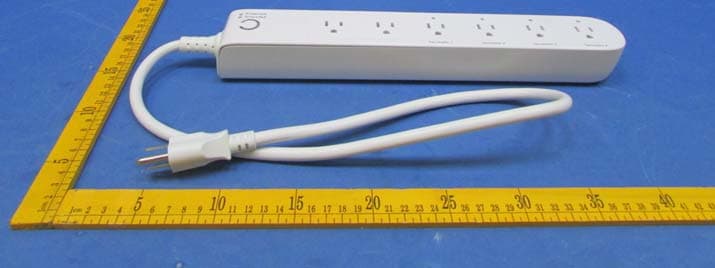
XBAZW069
Jan 25, 2016Smart Strip Gen5,Strip Gen5
Equipment Class
DXT - Part 15 Low Power Transceiver, Rx Verified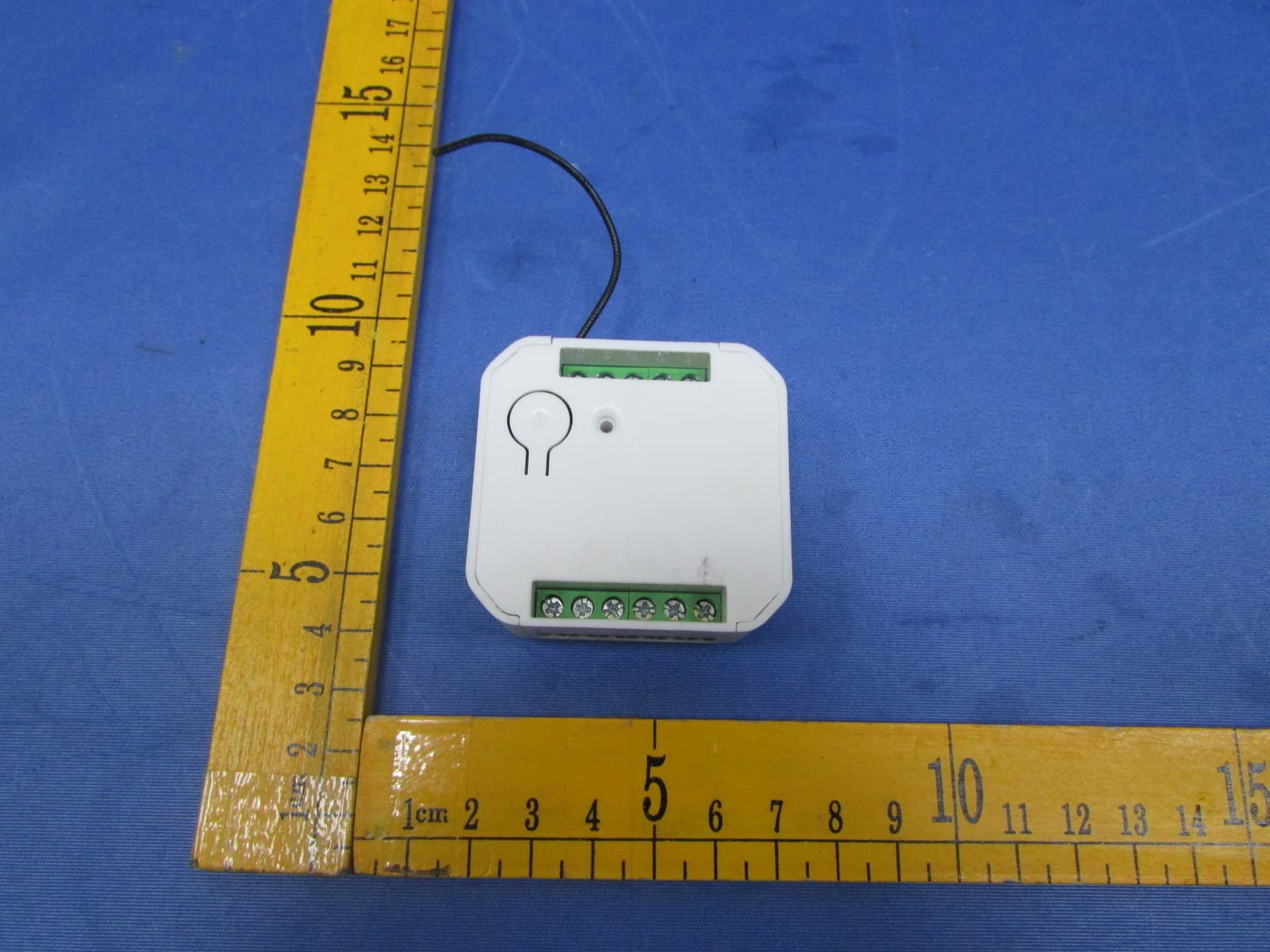
XBADSC14104
Dec 28, 2015DSC17103-ZWUS,DSC14104-ZWUS
Equipment Class
DXT - Part 15 Low Power Transceiver, Rx Verified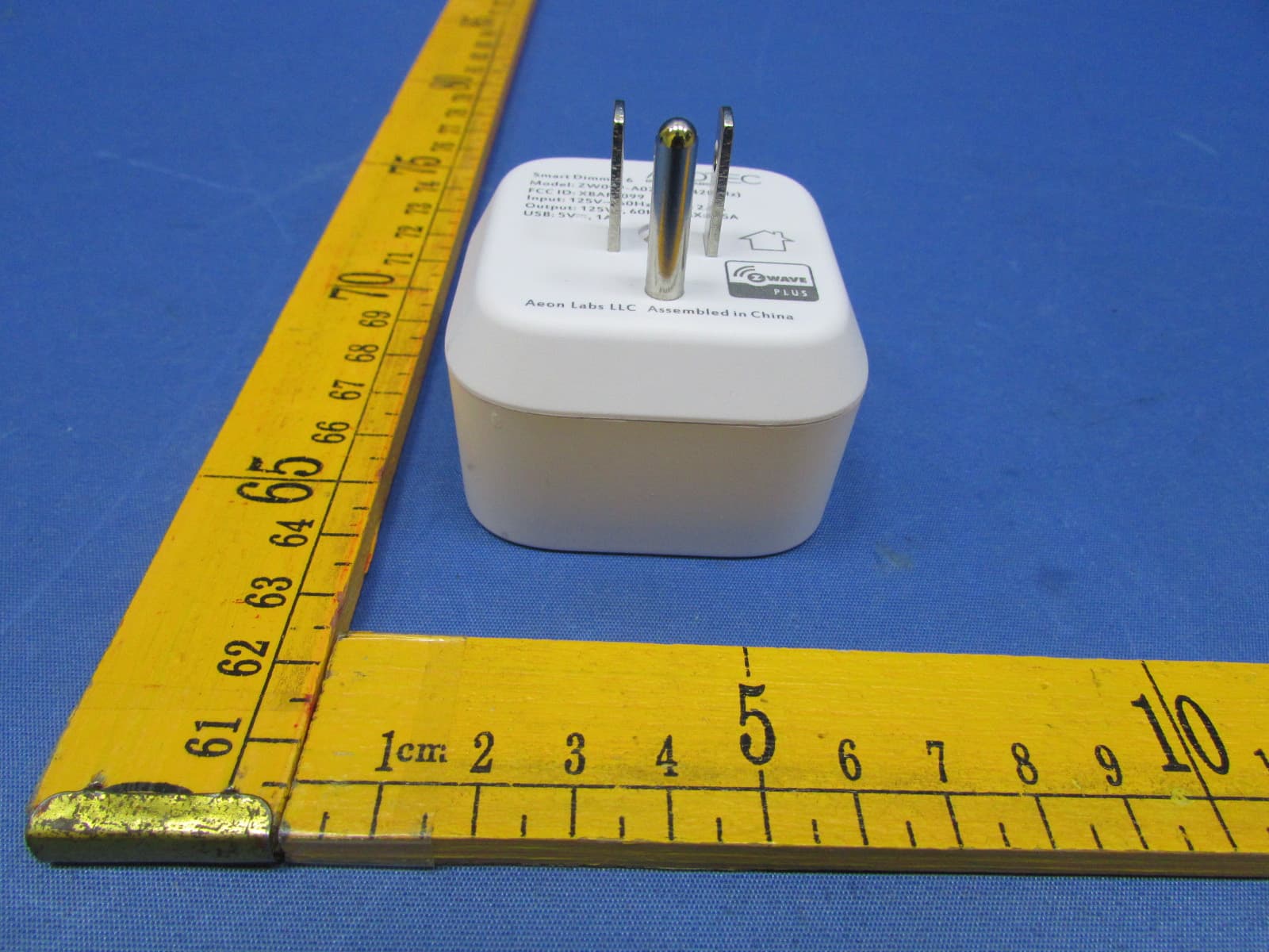
XBAFT099
Dec 23, 2015Smart Dimmer 6,Dimmer,Dimmer 6
Equipment Class
DXT - Part 15 Low Power Transceiver, Rx Verified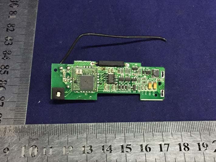
XBAZW120
Nov 30, 2015Door/Window Sensor Gen5
Equipment Class
DXT - Part 15 Low Power Transceiver, Rx Verified
XBAZW056
May 21, 2015Doorbell Gen5
Equipment Class
DXT - Part 15 Low Power Transceiver, Rx Verified