XBADSB54-ZWUSRECESSED DOOR SENSOR
Aeon Labs LLC.
Click to zoom
Application Details
- Equipment Class
- DXX - Part 15 Low Power Communication Device Transmitter
- Date of Grant
- May 29, 2013
- Application Purpose
- Original Equipment
- Date of Application
- May 29, 2013
- Equipment Note
- RECESSED DOOR SENSOR
- Frequency Range
- 908.40000000 - 908.42000000
- Company
- Aeon Labs LLC.
- Country
- United States
Documents & Files
Document Text
Text extracted from the exhibit documents filed with the FCC. Open a document above to read the original.
Users Manual
Recessed Door Sensor View the expanded manual: http://aeot.ec/spprt/recessed From Aeotec by Aeon Labs' Intelligence series comes the Recessed Door Sensor. Invisibly installed, it sits within a door and its frame to provide all the information needed by a Z-Wave system for security, safety, and ambiance, and it does it all without altering a room's aesthetics. Your Recessed Door Sensor is comprised of two parts: the larger Main Sensor and the smaller Magnetic Sensor. The larger Main Sensor Separate the Main Sensor's two sections by first removing its lid and then removing its internal components. Remove the clear battery insulator by pulling it away from the Main Sensor. Install your Recessed Door Sensor With the Main Sensor powered and activated, it is now time to inlay it within your selected doorframe and to also install the Magnetic Sensor. Top of the door Side of the door Prepare a space for the Main Sensor by drilling a hole into your doorframe using a 19mm wide drill bit. The hole should be 65 mm deep. Step 1 65mm deep 19mm Drill bit Drill a corresponding hole in your door. The hole should be 15 mm deep. As stated, the position of this hole should align exactly with the one hole you just created in the doorframe. Again, use a 19mm wide drill bit. Step 2 15mm deep 19mm Drill bit Doorframe Door Insert the Main Sensor into the hole you created in the doorframe then secure it using two screws. Step 3 With your door and doorframe prepared and the drill holes created, it's now time to mount both parts of your Recessed Door Sensor. Secure with screws Done Place a small amount of white glue (PVA) inside the hole you created for the Magnetic Sensor. Then place the sensor over and into the hole, and insert it by tapping gently on it with a rubber hammer. Step 4 Tap with hammerDone 1 3 Aeotec Recessed Door Sensor 2 Familiarise yourself with your door sensor Main Sensor LED Screw Hole Z-Wave Button Hole Magnetic Sensor The Magnetic Sensor A magnet in the plastic shell Using a slot-head screwdriver, remove the Main Sensor's lid by pressing gently against its exposed connector. Quick Start The installation of your Recessed Door Sensor has two major steps: the installation of the Main Sensor and the installation of the Magnetic Sensor. Powered by batteries, your door sensor will use wireless technology to talk to your Z-Wave network once installed. Prepare the Main Sensor The first step in installing your Recessed Door Sensor is to activate the Main Sensor. 1. 2. 3. With the battery insulator removed, reinsert the internal components into the Main Sensor's enclosure before reattaching its lid. The Main Sensor will now look as it did prior to step 1. 4. Note: Ensure that the Main Sensor's button aligns with the button hole of its lid. Before beginning it is important to select a suitable position for your Recessed Door Sensor. For the following instructions, your Recessed Door Sensor should be: Installed at the top of a door or the side of door. Positioned away from metal that could interfere with its magnetic functionality. This includes your door's plate, handle or lock mechanism. Installed in a suitable location to ensure a clear(at least 1mm) separation when the door is closed. Positioned exactly above or beside the hole you'll later in your door for the installation of the Magnetic Sensor. The rectangular areas highlighted above are the most appropriate installation positions. The gap between the two parts of your sensor must be at least 1mm. If they are not, re-affix the Main Sensor potentially by altering its hole. Step 5 Magnetic Sensor Main Sensor 1mm Magnetic Sensor Main Sensor Screw Hole Remove Operating distance: Up to 100 feet / 30 meters indoors and 300 feet / 100 meters outdoors. Battery: lithium cell CR2, 3 volt battery, 800mAh. Operating temperature: -10°C to 60°C. Relative humidity: 8%~80%. Aeon Labs warrants to the original purchaser of Products that for the Warranty Period (as defined below), the Products will be free from material defects in materials and workmanship. The foregoing warranty is subject to the proper installation, operation and maintenance of the Products in accordance with installation instructions and the operating manual supplied to Customer. Warranty claims must be made by Customer in writing within thirty (30) days of the manifestation of a problem. Aeon Labs' sole obligation under the foregoing warranty is, at Aeon Labs' option, to repair, replace or correct any such defect that was present at the time of delivery, or to remove the Products and to refund the purchase price to Customer. With your Recessed Door Sensor installed within a door and its frame, it's time to add it to your Z-Wave network. The following instructions tell you how to do this using Aeotec's Z-Stick and Minimote controllers. If you are using other products as your main Z-Wave controller, please refer to the part of their respective manuals that tells you how to add new devices to your network. If your Z-Stick is plugged into a gateway or a computer, unplug it. Take your Z-Stick to the door in which your Recessed Door Sensor has been installed. Press the Action Button on your Z-Stick. Press the Z-Wave Button on your Main Sensor with a small pin or toothpick. If your Recessed Door Sensor had been successfully linked to your network, the LED light will be blinking for a few seconds. If the linking was unsuccessful, the LED light will be blinking for 8 seconds before turning off. Press the Action Button on the Z-Stick to take it out of installation mode. Action Button Add your sensor to your Z-Wave network 4 1. 2. 3. 4. 5. 6. Take your Minimote to the door in which your Recessed Door Sensor has been installed. Press the Include button on your Minimote. Press the Z-Wave Button on your Main Sensor with a small pin or toothpick. If your Recessed Door Sensor had been successfully linked to your network, the LED light will be blinking for a few moments. If the linking was unsuccessful, the LED …
Text truncated - open the document above for the full version.
Cover Letter(s)
Aeon Labs LLC. Date: May 20, 2013 Federal Communications Commission Authorization and Evaluation Division Confidentiality Request regarding application for certification of FCC ID: XBADSB54-ZWUS Pursuant to Sections 0.457 and 0.459 of the Commission’s Rules, we hereby request confidential treatment of information accompanying this application as outlined below: Exhibit Type File Name Schematics Block Diagram Operational Description SCH.pdf BlockDiagram.pdf CircuitDescription.pdf The above materials contain trade secrets and proprietary information not customarily released to the public. The public disclosure of these materials may be harmful to the applicant and provide unjustified benefits to its competitors. The applicant understands that pursuant to Section 0.457 of the Rules, disclosure of this application and all accompanying documentation will not be made before the date of the Grant for this application. Sincerely, Aeon Labs LLC. ---------------------------------- William Li / Director of Business Development
Cover Letter(s)
Aeon Labs LLC. FCC ID:XBADSB54-ZWUS POWER OF ATTORNEY May 20, 2013 Federal Communications Commission Authorization and Evaluation Division 7435 Oakland Mills Road Columbia, MD 21046 To Whom It May Concern: We, the undersigned, hereby authorize Waltek Services (ShenZhen) Co., Ltd. (Philo Zhong) on our behalf, to apply to the Federal Communications Commission on our equipment. Any and all acts carried out by Waltek Services (ShenZhen) Co., Ltd. (Philo Zhong) on our behalf shall have the same effect as acts of our own. This authorization expires on May 19,2014. This is to advise that we are in full compliance with the Anti-Drug Abuse Act. We, Aeon Labs LLC., are not subject to a denial of federal benefits pursuant to Section 5301 of the Anti-Drug Act of 1988, 21 USC853a, and no party to the application is subject to a denial of federal benefits pursuant to that section. Sincerely, Aeon Labs LLC. ---------------------------------- William Li / Director of Business Development
External Photos
Waltek Services (Shenzhen) Co.,Ltd. http://www.waltek.com.cn Photographs - Constructional Details EUT - Appearance View Waltek Services (Shenzhen) Co.,Ltd. http://www.waltek.com.cn Waltek Services (Shenzhen) Co.,Ltd. http://www.waltek.com.cn
ID Label/Location Info
Waltek Services (Shenzhen) Co.,Ltd. http://www.waltek.com.cn Label Location The Label must not be a stick-on paper. The Label on these products must be permanently affixed to the product and readily visible at the time of purchase and must last the expected lifetime of the equipment not be readily detachable. ==END== FCC ID: XBADSB54-ZWUS This device complies with Part 15 of the FCC Rules. Operation is subject to the following two conditions:(1)this device may not cause harmful interference,and (2) this device must accept any interference received, including interference that may cause undesired operation.
ID Label/Location Info
Waltek Services (Shenzhen) Co.,Ltd. http://www.waltek.com.cn FCC ID Label Label sample Label sample for model: DSB54-ZWUS FCC ID: XBADSB54-ZWUS This device complies with Part 15 of the FCC Rules. Operation is subject to the following two conditions: (1) this device may not cause harmful interference, and (2) this device must accept any interference received, including interference that may cause undesired operation.
Internal Photos
Waltek Services (Shenzhen) Co.,Ltd. http://www.waltek.com.cn EUT - Open View Waltek Services (Shenzhen) Co.,Ltd. http://www.waltek.com.cn Waltek Services (Shenzhen) Co.,Ltd. http://www.waltek.com.cn EUT – RF Module Waltek Services (Shenzhen) Co.,Ltd. http://www.waltek.com.cn
Test Report
Report No.: WTS13S0503478E Page 1 of 31 TEST REPORT Waltek Services (Shenzhen) Co.,Ltd. http://www.waltek.com.cn FCC ID : XBADSB54-ZWUS Applicant : Aeon Labs LLC. Address : 121 Buckingham Drive,Unit 36,Santa Claras,California,United States,95051 Manufacturer : Aeon Labs LLC. Address : 1228 NORVELL ST.EL CERRITO, CA 94530 USA Equipment Under Test (EUT) : Product Name : Recessed Door Sensor Model No. : DSB54-ZWUS Rules : FCC CFR47 Part 15 Section 15.249: 2010, Date of Test : April 5~May 22, 2013 Date of Issue : May 23, 2013 Test Result : PASS* Remark: * The sample described above has been tested to be in compliance with the requirements of the rules listed above. The results shown in this test report refer only to the sample(s) tested, this test report cannot be reproduced, except in full, without prior written permission of the company. The report would be invalid without specific stamp of test institute and the signatures of compiler and approver. PERPARED BY: Waltek Services (Shenzhen) Co., Ltd. 1/F, Fukangtai Building, West of Baima Road., Songgang Street, Bao’an District, Shenzhen, China Tel: +86-755-83551033 Fax: +86-755-83552400 Compiled by: Approved by: Zero Zhou / Project Engineer Philo Zhong / Manager Report No.: WTS13S0503478E Page 2 of 31 Waltek Services (Shenzhen) Co.,Ltd. http://www.waltek.com.cn 2 Test Summary Test Items Test Requirement Result Restricted Band 15.205 PASS 20dB Bandwidth 15:215(c) PASS Conducted Emissions 15.207 PASS Radiated Emission 15.205(a) 15.209 15.249(a) PASS Antenna Requirement 15.203 PASS Report No.: WTS13S0503478E Page 3 of 31 Waltek Services (Shenzhen) Co.,Ltd. http://www.waltek.com.cn 3 Contents Page 1 COVER PAGE ............................................................................................................................................ 1 2 TEST SUMMARY .................................................................................................................................................... 2 3 CONTENTS .............................................................................................................................................................. 3 4 GENERAL INFORMATION .................................................................................................................................... 5 4.1 GENERAL DESCRIPTION OF E.U.T. ............................................................................................................. 5 4.2 DETAILS OF E.U.T. ...................................................................................................................................... 5 4.3 TEST FACILITY .............................................................................................................................................. 5 4.4 TEST LOCATION ........................................................................................................................................... 5 4.5 GENERAL CONDITION ................................................................................................................................... 6 4.5.1 Environmental condition of test site ......................................................................................................... 6 4.5.2 Test Mode ................................................................................................................................................... 6 5 EQUIPMENT USED DURING TEST .................................................................................................................... 7 5.1 EQUIPMENTS LIST ........................................................................................................................................ 7 5.2 MEASUREMENT UNCERTAINTY .................................................................................................................... 7 5.3 TEST EQUIPMENT CALIBRATION .................................................................................................................. 7 6 CONDUCTED EMISSION TEST ........................................................................................................................... 8 7 RADIATION EMISSION TEST .............................................................................................................................. 9 7.1 EUT OPERATION: ........................................................................................................................................ 9 7.2 TEST SETUP ............................................................................................................................................... 10 7.3 SPECTRUM ANALYZER SETUP ................................................................................................................... 11 7.4 TEST PROCEDURE ..................................................................................................................................... 11 7.5 CORRECTED AMPLITUDE & MARGIN CALCULATION .................................................................................. 11 7.6 RADIATED EMISSIONS TEST RESULT ........................................................................................................ 12 7.7 RADIATED EMISSION DATA ........................................................................................................................ 13 8 DUTY CYCLE ......................................................................................................................................................... 17 8.1 TEST PROCEDURE ..................................................................................................................................... 17 8.2 TEST RESULT ............................................................................................................................................. 17 9 20DB BANDWIDTH ......................................................................................................................…
Text truncated - open the document above for the full version.
Test Setup Photos
Waltek Services (Shenzhen) Co.,Ltd. http://www.waltek.com.cn Photographs of Testing Radiation Emission From 30MHz-1GHz Radiation Emission Above 1GHz
Contact Information
Applicant
William Li(Director of Business Development)
Test Firm
Waltek Services(Shenzhen) Co., Ltd.Philo zhong
Technical Specifications
| # | Rule Parts | Frequency Range | Power Output |
|---|---|---|---|
| 1 | 15C | 908.4 MHz - 908.42 MHz | - |
Other Applications from Aeon Labs LLC.
XBAZW069
Jan 25, 2016Smart Strip Gen5,Strip Gen5
Equipment Class
DXT - Part 15 Low Power Transceiver, Rx Verified
XBADSC14104
Dec 28, 2015DSC17103-ZWUS,DSC14104-ZWUS
Equipment Class
DXT - Part 15 Low Power Transceiver, Rx Verified
XBAFT099
Dec 23, 2015Smart Dimmer 6,Dimmer,Dimmer 6
Equipment Class
DXT - Part 15 Low Power Transceiver, Rx Verified
XBAZW120
Nov 30, 2015Door/Window Sensor Gen5
Equipment Class
DXT - Part 15 Low Power Transceiver, Rx Verified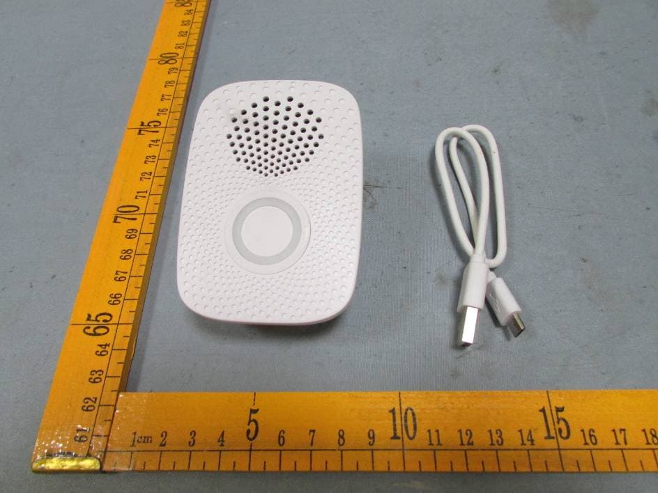
XBAZW056
May 21, 2015Doorbell Gen5
Equipment Class
DXT - Part 15 Low Power Transceiver, Rx Verified