XBADSC19103Micro Smart Energy Illuminator G2
Aeon Labs LLC.Application Details
- Equipment Class
- DXT - Part 15 Low Power Transceiver, Rx Verified
- Date of Grant
- Dec 22, 2011
- Application Purpose
- Original Equipment
- Date of Application
- Dec 22, 2011
- Equipment Note
- Micro Smart Energy Illuminator G2
- Frequency Range
- 908.40000000 - 908.42000000
- Company
- Aeon Labs LLC.
- Country
- United States
Documents & Files
Document Text
Text extracted from the exhibit documents filed with the FCC. Open a document above to read the original.
Users Manual
Aeon Labs Micro Smart Energy Illuminator (In-Wall Z-Wave Dimmer Module w/ Energy Monitor) Introduction: The Aeon Labs Micro Smart Energy Illuminator is a l ow-cost Z-Wave dimmer module specifically used to enable Z- Wave command and control (on/off/dim) for existing in-wa ll switches. It can also report immediate wattage consumption or kWh energy usage over a period of ti me. The wireless module is powered from the mains suppl y and is a three-wire design which requires a neutral con nection. In the event of power failure, non-volatile memory retains all programmed information relating to the units op erating status. It also is a repeater in the Z-Wave network. Actin g as a bridge for communication, it will forward Z-Wave co mmand messages to their destinations if the originating c ontroller is out of range from the destination node. By taking advantage of the Z-Wave mesh network, commands can be routed to their destination via intermediary “listening” Z-Wave products. Products that are Z-Wave certified can be used and communicate wi th other Z-Wave certified devices. In-Wall Electrical Installation Instructions : IMPORTANT: A licensed electrician with knowledge and understanding of electrical systems and electrical safety should complete the electrical installation inside the main circuit box (usually located outside of your house) . IMPORTANT: The electricity to the circuit must be shut off during installation for safety and to ensure that w ires are not shortcircuited during insallation which will ca use damage to the Micro Module. The Aeon Labs Micro Smart Energy Illuminator must f irst be powered by a 3-wire system in order to operate. Th e wiring diagram is as follows: Z-Wave Network Instructions : The Aeon Labs Micro Smart Energy Illuminator must b e paired (included) into a Z-Wave network before it c an receive Z-Wave commands to turn on/off/dim and repo rt its energy usage. The Smart Energy Illuminator can only communicate to devices within it’s own Z-Wave netwo rk. Note : The LED on the Micro Smart Energy Illuminator will blink if it is currently not paired into a Z-Wave n etwork. • Adding/Including/Pairing the Micro Smart Energy Illuminator into a Z-Wave Network 1. Press the button labeled “Include” on the Aeon Labs Minimote to begin the Z-Wave inclusion process. Note : To include the Aeon Labs Micro Smart Energy Illuminator with other controllers, please consult the operation manual for these controllers on how to include Z-Wave products into an existing network. For instructions on select partner gateways, visit www.aeon-labs.com/support . 2. While the Micro Smart Energy Illuminator is powered in a 3-wire system, press the button located near t he Status Indication LED. Or alternatively, the exter nal switch/button control can be pressed 6 times in qui ck succession. Troubleshooting : If the Aeon Labs Micro Smart Energy Illuminator was not successfully included into any Z-Wave network, the LED will be blinking slowly continuall y. If the Aeon Labs Micro Smart Energy Illuminator was succes sfully included to a Z-Wave network, the Status Indication LED will either be solid on or off (depending on if the swit ch is on or off) 10 seconds after the button was last pressed. • Removing/Resetting the Micro Smart Energy Illuminator from your Z-Wave Network 1. Press the button labeled “Remove” on the Aeon Labs Minimote Stick to begin the Z-Wave removal process. Note : To include the Aeon Labs Micro Smart Energy Illuminator with other controllers, please consult the operation manual for these controllers on how to include Z-Wave products into an existing network. For instructions on select partner gateways, visit www.aeon-labs.com/support . 2. While the Micro Smart Energy Illuminator is powered in a 3-wire system, press the button located near t he Status Indication LED. Or alternatively, the exter nal switch/button control can be pressed 6 times in qui ck succession. Troubleshooting : If the Aeon Labs Micro Smart Energy Illuminator was removed from the Z-Wave network, th e Status Indication LED will be blinking. If the Aeo n Labs Smart Energy Illuminator was not successfully remov ed from the Z-Wave network, the Status Indication LED will either be solid on or off (depending on if the swit ch is on or off) 10 seconds after the button was last pressed. • Turning On/Off/Dim the Micro Smart Energy Illuminator Use any of the below methods to turn on/off or dim the power through the Micro Smart Energy Illuminator. o Pressing the button on the external (Wall) switch will be able to toggle power flow (on/off) through the Smart Energy Illuminator (2-state flip/flop switch). If the mode of the micro module is set to momentary push button, holding the push button will dim the lights and a short press will toggle the lights between on/off. - 1 - - 2 - - 3 - - 4 - o Through the usage of Z-Wave commands built into Z-Wave certified controllers and gateways. (The specific Z-Wave commands supporting this function are the Basic Command Class and Multilevel Switch Command Class.) Please consult the operation manual for these controllers for specific instructions on controlling the Smart Energy Illuminator. o A short press on the button of the Smart Energy Illuminator will toggle the lights (on/off) while holding this button will dim the lights. • Change Mode on the External Switch/Button Control The Aeon Labs Micro Smart Energy Illuminator by def ault is set to be controlled via 2-state (flip/flop) extern al wall switch. Pushing the button 6 times in quick succes sion on the Micro Smart Energy Illuminator will swap betwee n this default mode and the momentary push button external wall switch mode. • Monitoring Energy Consumption The Aeon Labs Micro Smart Energy Illuminator can re port wattage energy usage or kWh energy usage to a Z-Wav e gateway or controller when requested. If this func tion is supported by the gateway/controller, the energy consumption will be displayed in the user interface of the g…
Text truncated - open the document above for the full version.
Cover Letter(s)
Aeon Labs LLC. Authorization Letter Number: CF101 Version: V01 Date: 01-02-2010 We, (the approval holder) Company name Aeon Labs LLC. Addresss 121 Buckingham drive, unit 36 City Santa Clara Country CA95051, USA declare that the following representative (agent): Name (person) Daniel Zhu Company name Anbotek Compliance Laboratory Limited Addresss 1/F, 1 /Build, SEC Industrial Park, No. 4 Qianhai Road, Nanshan District City Shenzhen Country China is hereby authorized to apply the following equipment for certification on our behalf: Product Description Micro Smart Energy Illuminator G2 Type or Model(s) DSC19103-ZWUS, DSC27103-ZWUS Tradename or Brand(s) N.A. We also authorize Teleconformity (Mr. M. Koop, Rietven 31, 7534NH Enschede, The Netherlands) to process this application. Attestation: City and Country: Date: Name: (this must be a person) Function: Signature: (or official company stamp) Santa Clara 2011-12-15 William Li Director of Business Development
Cover Letter(s)
Aeon Labs LLC. FCC Confidentiality Request Number: CF303 Version: V01 Date: 01-02-2010 To the FCC and FCC TCB handling this application for certification Pursuant to 47 CFR Section 0.459(a) & (b), we, (the applicant / grantee) Company name Aeon Labs LLC. Addresss 121 Buckingham drive, unit 36 City Santa Clara Country CA95051, USA request non-disclosure and confidential treatment for our certification under: Grantee Code Product Number FCC ID: XBA DSC19103 of the following materials submitted within this certification application: (please cross what is applicable, or add other documents) √ Schematics Diagrams √ Block Diagrams √ Circuit Description User Manual Above materials contain secrets, proprietary and technical information, which would customarily be guarded from competitors under 47 CFR, section 0.457(d)(2). Disclosure or publication or any portion of this company confidential material to other parties could cause substantial competitive harm and provide unjustified benefits for competitors. We understand that pursuant to 47 CFR section 0.457(d)(1)(ii) disclosure of the applicant and all accompanying documentation will not be made before the date of the grant. Attestation: City and Country: Date: Name: (this must be a person) Function: Signature: (or official company stamp) Santa Clara, USA 2011-12-15 William Li Director of Business Development
External Photos
Page 20 of 21 FCC ID: XBADSC19103 Anbotek Compliance Laboratory Limited Report No.201111779F Figure 1 The EUT-Front View Figure 2 The EUT-Back View
ID Label/Location Info
The proposed Label Location on EUT Proposed FCC ID Label Location Proposed Label Location on EUT The EUT-FrontView/Proposed FCC ID Label Location
ID Label/Location Info
FCC ID Label Sample for FCC ID: XBADSC19103 FCC ID: XBADSC19103 This device complies with Part 15 of the FCC Rules. Operation is subject to the following two conditions: 1. This device may not cause harmful interference, and 2. This device must accept any interference received, including interference that may cause undesired operation.
Internal Photos
Page 21 of 21 FCC ID: XBADSC19103 Anbotek Compliance Laboratory Limited Report No.201111779F Figure 3 PCB of the EUT-Front View Figure 4 PCB of the EUT-Back View
Test Report
Page 1 of 21 FCC ID: XBADSC19103 Anbotek Compliance Laboratory Limited Report No.201111779F FCC TEST REPORT for Aeon Labs LLC. Micro Smart Energy Illuminator G2 Model No.: DSC19103-ZWUS, DSC27103-ZWUS Report Number : 201111779F Date of Test : Nov. 30~Dec. 13, 2011 Date of Report : Dec. 15, 2011 Prepared for : Aeon Labs LLC. Address : 121 Buckingham drive, unit36 santa claras CA95051 USA Tel: (1) 408-248 2013 Fax: (1) 408-248 2013 Prepared By : Anbotek Compliance Laboratory Limited Address : 1/F, 1 /Building, SEC Industrial Park, No. 4 Qianhai Road, Nanshan District, Shenzhen, 518054, China Tel: (86) 755-26014771 Fax: (86) 755-26014772 Page 2 of 21 FCC ID: XBADSC19103 Anbotek Compliance Laboratory Limited Report No.201111779F TABLE OF CONTENT Description Page Test Report 1. GENERAL INFORMATION .........................................................................................................4 1.1. Description of Device (EUT)....................................................................................................................4 1.2. Description of Test Facility ......................................................................................................................5 1.3. Measurement Uncertainty.........................................................................................................................5 2. MEASURING DEVICE AND TEST EQUIPMENT.................................................................... 6 3. TEST PROCEDURE ....................................................................................................................... 7 4. CONDUCTED LIMITS .................................................................................................................. 8 4.1. Block Diagram of Test Setup ...................................................................................................................8 4.2. Power Line Conducted Emission Measurement Limits (15.207) .............................................................8 4.3. Configuration of EUT on Measurement ...................................................................................................8 4.4. Operating Condition of EUT ....................................................................................................................8 4.5. Test Procedure ..........................................................................................................................................9 4.6. Power Line Conducted Emission Measurement Results ..........................................................................9 5. RADIATION INTERFERENCE.................................................................................................. 12 5.1. Requirements (15.249, 15.209): .............................................................................................................12 5.2 Test Procedure .........................................................................................................................................12 5.3 Test Results..............................................................................................................................................12 6. OCCUPIED BANDWIDTH..........................................................................................................15 6.1. Requirements (15.249): ..........................................................................................................................15 6.2 Test Results..............................................................................................................................................15 7. PHOTOGRAPH............................................................................................................................. 18 7.1. Photo of Power Line Conducted Emission Measurement ......................................................................18 7.2. Photo of Radiation Emission Test ..........................................................................................................18 APPENDIX I (Photos of EUT) (2 Pages) Page 3 of 21 FCC ID: XBADSC19103 Anbotek Compliance Laboratory Limited Report No.201111779F TEST REPORT Applicant : Aeon Labs LLC. Manufacturer : Aeon Labs LLC. EUT : Micro Smart Energy Illuminator G2 Model No. : DSC19103-ZWUS, DSC27103-ZWUS Serial No. : N/A Rating : AC 120V, 60Hz, 2.5A, 300W Trade Mark : N/A Measurement Procedure Used: FCC Part15 Subpart C, Paragraph 15.207, 15.209&15.249 The device described above is tested by Anbotek Compliance Laboratory Limited to determine the maximum emission levels emanating from the device and the severe levels of the device can endure and its performance criterion. The measurement results are contained in this test report and Anbotek Compliance Laboratory Limited is assumed full of responsibility for the accuracy and completeness of these measurements. Also, this report shows that the EUT (Equipment Under Test) is technically compliant with the FCC Part 15 Subpart C requirements. This report applies to above tested sample only and shall not be reproduced in part without written approval of Anbotek Compliance Laboratory Limited Date of Test : Nov. 30~Dec. 13, 2011 Prepared by : (Tested Engineer / Andy Chen) Reviewer : (Project Manager / Coco Xiang) Approved & Authorized Signer : (Manager / Henry Yang) Page 4 of 21 FCC ID: XBADSC19103 Anbotek Compliance Laboratory Limited Report No.201111779F 1. GENERAL INFORMATION 1.1. Description of Device (EUT) EUT : Micro Smart Energy Illuminator G2 Model Number : DSC19103-ZWUS, DSC27103-ZWUS (Note: All Models are the same except the model number & Low-voltage circuit of appliances, so we prepare “DSC19103-ZWUS” for EMC test only.) Test Power Supply : AC 120V, 60Hz Frequency : 908.42MHz / 908.40MHz Antenna : Gain is 3dBi (The antenna used in this product is Monopole antenna) Applicant : Aeon Labs LLC. Address : 121 Buckingham drive, unit36 santa claras CA95051 USA Manufacturer : Aeon …
Text truncated - open the document above for the full version.
Test Setup Photos
Page 18 of 21 FCC ID: XBADSC19103 Anbotek Compliance Laboratory Limited Report No.201111779F 7. PHOTOGRAPH 7.1. Photo of Power Line Conducted Emission Measurement 7.2. Photo of Radiation Emission Test
Contact Information
Applicant
William Li(Director of Business Development)
Technical Contact
TeleconformityMark Koop
[email protected]+31 84 8395876
Rietven 31 · Enschede, Overyssel · Netherlands
Test Firm
Shenzhen Anbotek Compliance Laboratory LimitedDaniel zhu
[email protected]86-755-26014771
Technical Specifications
| # | Rule Parts | Frequency Range | Power Output |
|---|---|---|---|
| 1 | 15C | 908.4 MHz - 908.42 MHz | - |
Other Applications from Aeon Labs LLC.
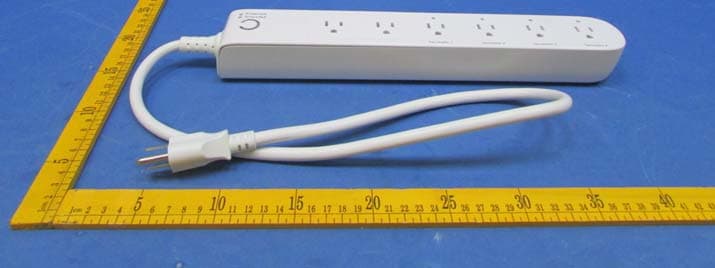
XBAZW069
Jan 25, 2016Smart Strip Gen5,Strip Gen5
Equipment Class
DXT - Part 15 Low Power Transceiver, Rx Verified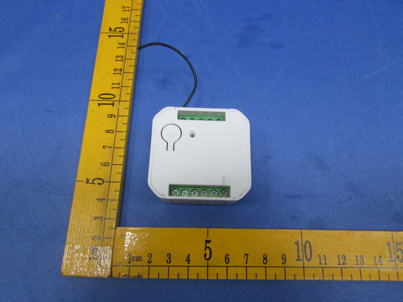
XBADSC14104
Dec 28, 2015DSC17103-ZWUS,DSC14104-ZWUS
Equipment Class
DXT - Part 15 Low Power Transceiver, Rx Verified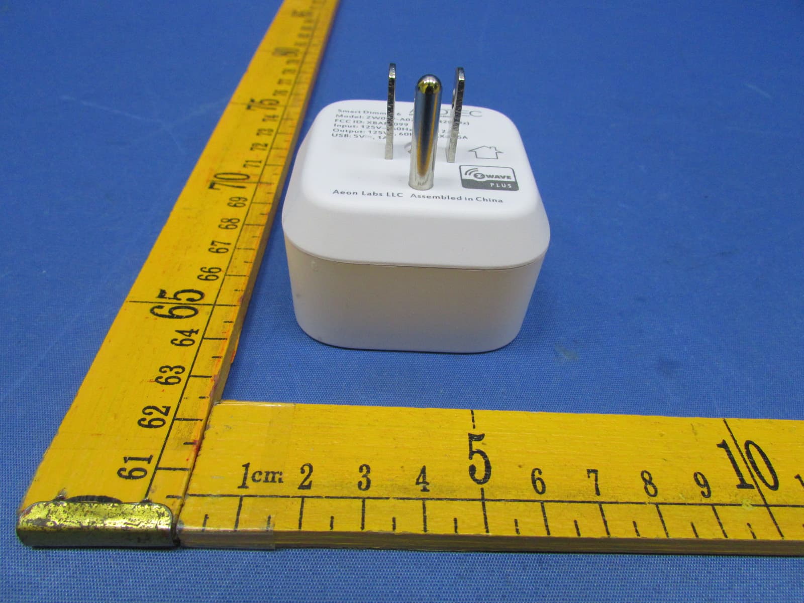
XBAFT099
Dec 23, 2015Smart Dimmer 6,Dimmer,Dimmer 6
Equipment Class
DXT - Part 15 Low Power Transceiver, Rx Verified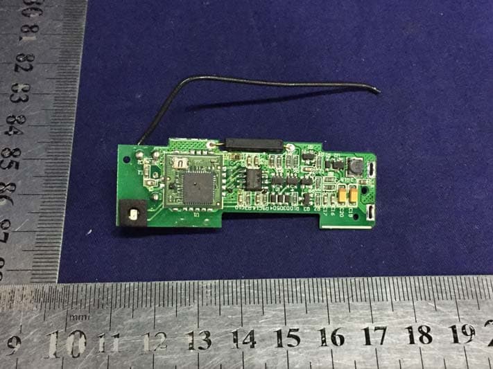
XBAZW120
Nov 30, 2015Door/Window Sensor Gen5
Equipment Class
DXT - Part 15 Low Power Transceiver, Rx Verified
XBAZW056
May 21, 2015Doorbell Gen5
Equipment Class
DXT - Part 15 Low Power Transceiver, Rx Verified