XBAZW074MultiSensor Gen5
Aeon Labs LLC.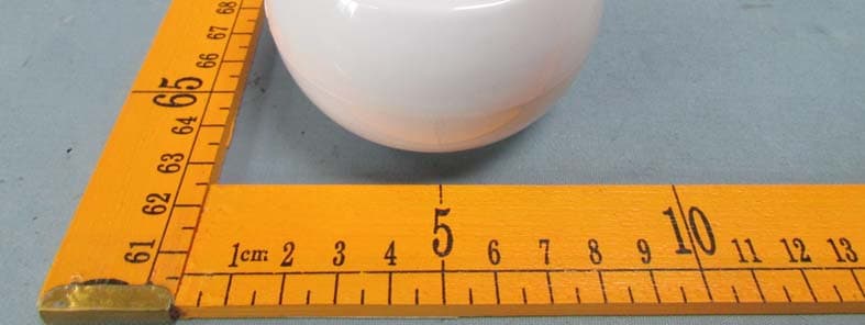
Click to zoom
Application Details
- Equipment Class
- DXT - Part 15 Low Power Transceiver, Rx Verified
- Date of Grant
- Nov 13, 2014
- Application Purpose
- Original Equipment
- Date of Application
- Nov 13, 2014
- Equipment Note
- MultiSensor Gen5
- Frequency Range
- 908.40000000 - 908.42000000
- Company
- Aeon Labs LLC.
- Country
- United States
Documents & Files
Document Text
Text extracted from the exhibit documents filed with the FCC. Open a document above to read the original.
Users Manual
View the expanded manual: http://aeotec.com/support Aeotec by Aeon Labs MultiSensor. Motion sensor. Humidity sensor. Thermometer. Light sensor. The corner of your room just got smart. Aeotec by Aeon Labs’ MultiSensor looks like a motion sensor and it acts like one too. But it’s also so much more. Installing this 1 piece of Z-Wave® technology is the same as installing 4 pieces of Z-Wave technology. Your home control network will immediately understand motion, temperature, humidity and light readings wherever MultiSensor installed. Those intelligent readings will equate to intelligence automation. And intelligent automation will give you the perfect, smart home. Your MultiSensor comes packaged with a number of accessories that will help with its installation and operation. Your MultiSensor can be powered by battery or by USB with an appropriate adaptor. For the purposes of installation and setup, and even if you intend to power your sensor with batteries, we recommend utilizing the provided USB cable for setup. For this you’ll need an adaptor to plug your USB cable into, this can include any USB port on a computer and most mobile phone chargers. These first steps can be performed in any location with your home, and not necessarily in your MultiSensor’s final installation location. For a USB powered installation; 1. Remove the rear part of your sensor by twisting the battery cover in a counter- clockwise motion and separating the two parts of your sensor. 1. If your Z-Stick is plugged into a gateway or a computer, unplug it. 2. Take your Z-Stick to your MultiSensor. 3. Press the Action Button on your Z-Stick. 4. Press the Z-Wave Button on your MultiSensor. 5. You can test if your MultiSensor has been successfully synced with your Z-Wave network by pressing its Z-Wave Button. If you press the button and your sensor’s LED illuminates for a few seconds, then syncing has been successful. If the LED blinks when the button is pressed, the syncing has been unsuccessful and you should repeat the above steps. 6. Press the Action Button on the Z-Stick to return it to standard operating mode, then return it to your gateway or computer. 1. Take your Minimote to your MultiSensor. 2. Press the Include button on your Minimote. 3. Press the Z-Wave Button on your MultiSensor. 4. You can test if your MultiSensor has been successfully synced with your Z-Wave network by pressing its Z-Wave Button. If you press the button and your sensor’s LED illuminates for a few seconds, then syncing has been successful. If the LED blinks when the button is pressed, the syncing has been unsuccessful and you should repeat the above steps. 5. Press any button on your Minimote to return it to standard operating mode. MultiSensor can bring its intelligent readings to many locations of your home. That includes outside of your home. MultiSensor is weatherized and can operate outdoors in elements such as rain and snow. Please note that when installed outdoors, your MultiSensor should only be relied on for temperature, light and humidity readings and that the motion sensing capabilities should be disabled on your gateway in order to avoid false readings. While light can impact on the quality of motion readings, it’s also important to understand things that may impact on other readings within your home. Specifically, your MultiSensor should not be installed in areas of artificial temperature change. Thus, when selecting a location, avoid placing it beside or near air conditioners, humidifiers, and heaters, and avoid positioning it directly opposite a window or direct sunlight. Selecting a location for your MultiSensor to be installed depends on the use case. Whatever the case or the installation location, please ensure that it fits with your sensor’s effective motion sensing range as described in these diagrams. For a battery powered installation; 1. Remove the rear part of your sensor as shown in the previous step 1. 2. Insert 4 AAA batteries oriented according to the picture below. Your MultiSensor is now powered on. It’s now time to sync your MultiSensor with a Z-Wave network. The following instructions explain how to do this using a Z-Stick or a Minimote from Aeotec. If you’re using an alternative controller for your Z-Wave network, please refer to its user manual for network inclusion instructions. If you’re using a Z-Stick: If you’re using a Minimote: For ceiling mounting using the Back-Mount Plate: Further, for optimal performance your MultiSensor should NOT be mounted directly on or near metal framing or other large metallic objects. Large metal objects may weaken the Z-Wave wireless signal. If selecting an outdoor location, it’s important to position your MultiSensor in a sheltered location. It is best if your MultiSensor is not directly exposed to rain and integral that the humidity venting on your MultiSensor is. As such, during installation you should orient your MultiSensor according to the following diagram so that the sensor perforations on the side of your sensor are facing downwards. With your MultiSensor now part of your Z-Wave network, it’s time to finish its physical installation. There are 2 ways that your MultiSensor can be mounted on on a wall or ceiling. Using the Back-Mount Plate, you can mount it flat against a wall or ceiling. Using the Back-Mount Arm you can mount it on a surface or in a corner and angle it as desired. To physically install your MultiSensor; 1. Reattach the two parts of your MultiSensor to each other. To do this, align the lock/unlock half-dimple markers that are under the unlock symbol and then twist in a clockwise motion. 2. If used the USB cable to power your MultiSensor, ensure that power can be provided to your desired installation location. Please note that when installed in areas that where the temperature can drop below -10°C, it is advised that mains power is used and battery power is not. 3. Attach your desired mounting accessory. This can be the Back-Mount Plate or the Back-Moun…
Text truncated - open the document above for the full version.
Cover Letter(s)
Aeon Labs LLC. Date: Nov 14, 2014 Subject: authorization about USB port To whom it May concern, Statement The USB port is designed in the interior of the product, and it is only used for procedure debugs. Yours sincerely, Signature: William Li/Director of Business Development A eon Labs LLC.
Cover Letter(s)
Aeon Labs LLC. Federal Communications Commission Authorization and Evaluation Division Date:2014/10/20 Confidentiality Request regarding application for certification of FCC ID:XBAZW074. Pursuant to Sections 0.457 and 0.459 of the Commission’s Rules, we hereby request confidential treatment of information accompanying this application as outlined below: Exhibit Type File Name Schematics Block Diagram Operational Description XBAZW074_SCH.pdf XBAZW074_BlockDiagram.pdf XBAZW074_CircuitDescription.pdf The above materials contain trade secrets and proprietary information not customarily released to the public. The public disclosure of these materials may be harmful to the applicant and provide unjustified benefits to its competitors. The applicant understands that pursuant to Section 0.457 of the Rules, disclosure of this application and all accompanying documentation will not be made before the date of the Grant for this application. Sincerely, Aeon Labs LLC. ................................................... Signature ................................................... William Li / Director of Business Development
Cover Letter(s)
Aeon Labs LLC. FCC ID:XBAZW074 POWER OF ATTORNEY Date:2014/10/20 Federal Communications Commission Authorization and Evaluation Division 7435 Oakland Mills Road Columbia, MD 21046 To Whom It May Concern: We, the undersigned, hereby authorize Waltek Services (ShenZhen) Co., Ltd. (Philo Zhong) on our behalf, to apply to the Federal Communications Commission on our equipment. Any and all acts carried out by Waltek Services (ShenZhen) Co., Ltd. (Philo Zhong) on our behalf shall have the same effect as acts of our own. This authorization expires on 2015/10/19. This is to advise that we are in full compliance with the Anti-Drug Abuse Act. We,Aeon Labs LLC. are not subject to a denial of federal benefits pursuant to Section 5301 of the Anti-Drug Act of 1988, 21 USC853a, and no party to the application is subject to a denial of federal benefits pursuant to that section. Sincerely, Aeon Labs LLC. ................................................... Signature ................................................... William Li/Director of Business Development
External Photos
Waltek Services (Shenzhen) Co.,Ltd. http://www.waltek.com.cn Photographs - Constructional Details ZW074- A - External View Waltek Services (Shenzhen) Co.,Ltd. http://www.waltek.com.cn Waltek Services (Shenzhen) Co.,Ltd. http://www.waltek.com.cn
ID Label/Location Info
FCC Label Sample for model: ZW074-A FCC ID: XBAZW074 This device complies with part 15 of the FCC Rules . Operation is subject to the following two conditions: (1) This device may not cause harmful interference, and (2) this dev ice must accept any interference received, including interference that may cause undesired operation.
Internal Photos
Waltek Services (Shenzhen) Co.,Ltd. http://www.waltek.com.cn ZW074-A - Internal View ANT Waltek Services (Shenzhen) Co.,Ltd. http://www.waltek.com.cn Waltek Services (Shenzhen) Co.,Ltd. http://www.waltek.com.cn Waltek Services (Shenzhen) Co.,Ltd. http://www.waltek.com.cn Waltek Services (Shenzhen) Co.,Ltd. http://www.waltek.com.cn
Test Report
TEST REPORT Waltek Services (Shenzhen) Co.,Ltd. http://www.waltek.com.cn Page 1 of 23 Reference No. .................... : WTS14S1019245E FCC ID ................................ : XBAZW074 Applicant ............................ : Aeon Labs LLC. Address .............................. : 121 Buckingham Drive Unit 36 Santa Claras California United States Manufacturer .................... : Fantem Technologies (Shenzhen) Co.,Ltd Address .............................. : North,3/F, Yitoa Technology Industrial Park,Baihua Yuan Rd.,The Second Industrial Area,Guangming Sub-district Office,Guangming New District,Shenzhen, Guangdong, China Product Name .................... : MultiSensor Gen5 Model No. ........................... : ZW074-A Trade Mark ......................... : AEON LABS/AEOTEC Standards .......................... : FCC CFR47 Part 15 Section 15.249: 2014 Date of Receipt sample .... : Oct.19, 2014 Date of Test ....................... : Oct.21~29, 2014 Date of Issue ...................... : Nov. 04, 2014 Test Result ......................... : Pass * Remarks: The results shown in this test report refer only to the sample(s) tested, this test report cannot be reproduced, except in full, without prior written permission of the company. The report would be invalid without specific stamp of test institute and the signatures of compiler and approver. Prepared By: Waltek Services (Shenzhen) Co., Ltd. Address: 1/F., Fukangtai Building, West Baima Road, Songgang Street, Baoan District, Shenzhen, Guangdong, China Testing location: The same as above Tel :+86-755-83551033 Fax:+86-755-83552400 Compiled by: Approved by: Zero.zhou / Project Engineer Philo Zhong / Manager Reference No.: WTS14S1019245E Page 2 of 23 Waltek Services (Shenzhen) Co.,Ltd. http://www.waltek.com.cn 2 Test Summary Test Items Test Requirement Result Conducted Emissions 15.207 PASS Radiated Emission 15.249(a) 15.209 15.205(a) PASS Periodic Operation 15.35(c) PASS Outside of Band Emission 15.249 15.205 15.209 PASS 20dB Bandwidth 15:215(c) PASS Antenna Requirement 15.203 PASS Reference No.: WTS14S1019245E Page 3 of 23 Waltek Services (Shenzhen) Co.,Ltd. http://www.waltek.com.cn 3 Contents Page 1 COVER PAGE ........................................................................................................................................... 1 2 TEST SUMMARY .................................................................................................................................................. 2 3 CONTENTS ............................................................................................................................................................ 3 4 GENERAL INFORMATION .................................................................................................................................. 4 4.1 GENERAL DESCRIPTION OF E.U.T. ............................................................................................................ 4 4.2 DETAILS OF E.U.T. ..................................................................................................................................... 4 4.3 TEST FACILITY ............................................................................................................................................ 4 5 EQUIPMENT USED DURING TEST .................................................................................................................. 5 5.1 EQUIPMENTS LIST ...................................................................................................................................... 5 5.2 MEASUREMENT UNCERTAINTY ................................................................................................................... 5 5.3 TEST EQUIPMENT CALIBRATION................................................................................................................. 5 6 RADIATION EMISSION TEST ............................................................................................................................ 6 6.1 EUT OPERATION ........................................................................................................................................ 6 6.2 TEST SETUP ............................................................................................................................................... 7 6.3 SPECTRUM ANALYZER SETUP .................................................................................................................... 8 6.4 TEST PROCEDURE ...................................................................................................................................... 9 6.5 TEST RESULT ........................................................................................................................................... 10 7 PERIODIC OPERATION .................................................................................................................................... 11 8 OUTSIDE OF BAND EMISSION ....................................................................................................................... 12 8.1 TEST PROCEDURE .................................................................................................................................... 12 8.2 TEST RESULT ........................................................................................................................................... 12 9 20 DB BANDWIDTH MEASUREMENT ........................................................................................................... 13 9.1 TEST PROCEDURE .................................................................................................................................... 13 9.2 TEST RESULT ........................................................................................................................................... 13 10 ANTENNA REQUIREMENT ...........................................................................…
Text truncated - open the document above for the full version.
Test Setup Photos
Waltek Services (Shenzhen) Co.,Ltd. http://www.waltek.com.cn Photographs- Model ZW074-A Test Setup Radiation Emission From 30MHz -1GHz Radiation Emission Above 1GHz
Contact Information
Applicant
William Li(Director of Business Development)
Test Firm
Waltek Services(Shenzhen) Co., Ltd.Philo zhong
Technical Specifications
| # | Rule Parts | Frequency Range | Power Output |
|---|---|---|---|
| 1 | 15C | 908.4 MHz - 908.42 MHz | - |
Other Applications from Aeon Labs LLC.
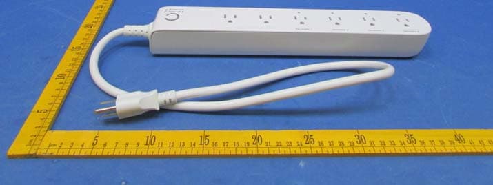
XBAZW069
Jan 25, 2016Smart Strip Gen5,Strip Gen5
Equipment Class
DXT - Part 15 Low Power Transceiver, Rx Verified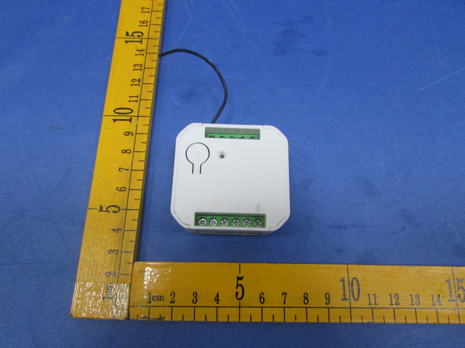
XBADSC14104
Dec 28, 2015DSC17103-ZWUS,DSC14104-ZWUS
Equipment Class
DXT - Part 15 Low Power Transceiver, Rx Verified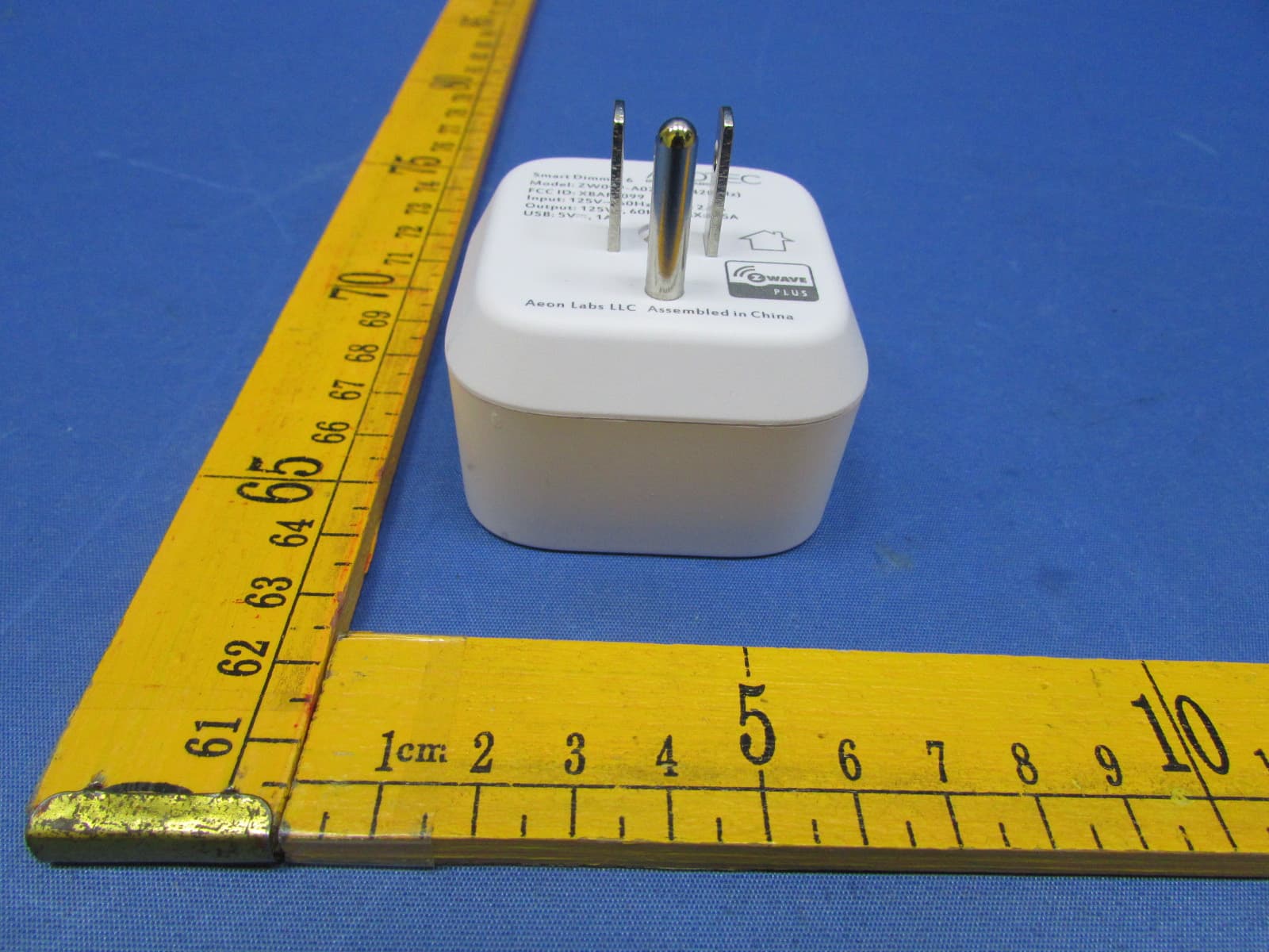
XBAFT099
Dec 23, 2015Smart Dimmer 6,Dimmer,Dimmer 6
Equipment Class
DXT - Part 15 Low Power Transceiver, Rx Verified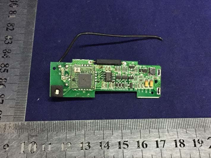
XBAZW120
Nov 30, 2015Door/Window Sensor Gen5
Equipment Class
DXT - Part 15 Low Power Transceiver, Rx Verified
XBAZW056
May 21, 2015Doorbell Gen5
Equipment Class
DXT - Part 15 Low Power Transceiver, Rx Verified