XT5PGIDTDesktop Video Magnifier
Technologies Humanware Inc.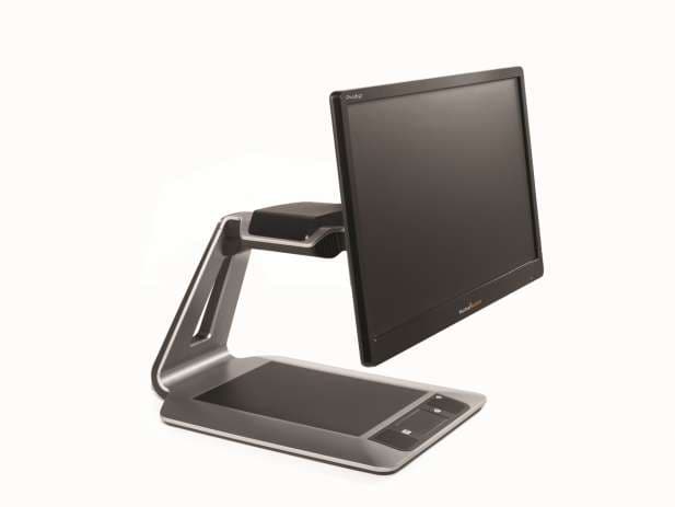
Click to zoom
Application Details
- Equipment Class
- DSS - Part 15 Spread Spectrum Transmitter
- Date of Grant
- Mar 23, 2015
- Application Purpose
- Original Equipment
- Date of Application
- Mar 23, 2015
- Equipment Note
- Desktop Video Magnifier
- Frequency Range
- 2402.00000000 - 2480.00000000
- Company
- Technologies Humanware Inc.
- Country
- Canada
Documents & Files
Document Text
Text extracted from the exhibit documents filed with the FCC. Open a document above to read the original.
Users Manual
Page 1 CONTENTS Chapter 1 – Introduction ................................................................ 2 Chapter 2 – Getting to know your Prodigi ..................................... 3 Box contents .............................................................................. 3 Prodigi Desktop at a glance ....................................................... 4 Setting up .................................................................................. 7 Chapter 3 – Using Prodigi ........................................................... 10 Spot Reading ........................................................................... 10 Auto Reading ........................................................................... 12 Normal Reading ....................................................................... 15 Manual Tasks .......................................................................... 15 Chapter 4 – Switching to Standard Interface .............................. 17 Using Prodigi (Standard Interface) .......................................... 18 Spot Reading (Standard Interface) ...................................... 18 Normal Reading (Standard Interface) .................................. 20 Auto Reading (Standard Interface) ...................................... 21 Manual Tasks (Standard Interface) ...................................... 22 Using the Carousel menu ........................................................ 23 Viewing saved Documents ...................................................... 24 Chapter 5 – Choosing your Contrast ........................................... 25 Chapter 6 – Viewing a Video ....................................................... 27 Chapter 7 – Changing your Settings ........................................... 28 Chapter 8 – Standing By and Powering off ................................. 32 Chapter 9 – Software Update ...................................................... 32 Chapter 10 – Troubleshooting ..................................................... 35 Appendix A: Safety and Maintenance ......................................... 37 Appendix B: Specifications .......................................................... 40 Appendix C: Warranty ................................................................. 41 Page 2 CHAPTER 1 – INTRODUCTION Thank you for purchasing Prodigi, the touch-controlled personal vision assistant system from HumanWare, global leader in assistive technologies for people who have low vision. Prodigi is a simple, intelligent, and adaptable line of products aimed at restoring and maintaining independence for people living with vision loss. Prodigi Desktop will allow you to magnify and read documents, continue your favorite hobbies and activities, and carry out a wide range of manual tasks with ease and simplicity. Carefully read the operating and safety instructions described in this user guide prior to using your Prodigi. This user guide describes the system functions based on Prodigi’s manufacturer default settings. If you have any questions about your system, please contact HumanWare Customer Service by consulting the contact information in the back of this user guide. Copyright 2015 by Technologies HumanWare Inc., all rights reserved. No part of this publication may be reproduced or distributed in any form or by any means, or stored in a database or retrieval system, without the prior written permission of Technologies HumanWare Inc. Page 3 CHAPTER 2 – GETTING TO KNOW YOUR PRODIGI BOX CONTENTS Base box Base Unit Power Supply Power Cable Unboxing Guide Getting Started Guide User Guide Packing and Unpacking Guide Colored button overlay stickers Warranty Sheet Assembly kit (if your screen is not assembled): Screen Slider, 4 thumb screws, 2 screws, 1 Torx key, 1 cable clip, 1 masking membrane Screen box 20 or 24 inch screen (if your screen is not assembled) Page 4 PRODIGI DESKTOP AT A GLANCE Front Face 1. Screen 2. Viewing Zone 3. Control Panel 4. Plus-Minus keys 5. Audio Port 1 3 2 4 5 6 Page 5 6. USB Ports (2) Control Panel 1. Speakers (2) 2. Settings Button 3. Back Button 4. Read Button 5. Touchpad 6. Touchpad Click 7. Zoom Up-Down Buttons 8. Power Button 1 1 5 4 3 2 6 7 8 Page 6 Back Side 1. Power Connector 2. USB Port (factory use) 1 2 Page 7 SETTING UP 1. Pull the Base out of its box by holding the temporary cardboard handle, and place it on a flat and level surface. Note: The handle should only be used once. 2. (If the screen is assembled, skip to step 5.) Carefully take the screen out of its box and place it face down on a flat surface. Use the 4 thumb screws to secure the screen slider in place. Make sure the tactile HumanWare logo on the screen slider is facing towards the top of the screen (1). 1 Page 8 IMPORTANT: Use caution while handling the screen to avoid scratching it. 3. Tilt the screen forward and carefully insert the screen slider into the Base (1). Use the Torx key to tighten the 2 screws into the Base (2). Then, apply the masking membrane over the 2 screws (3). 4. Connect the DC cable into the DC port (1). Then, insert the DVI cable into the DVI port and tighten the 2 included screws (2). Use the cable clip to attach the cables behind the screen (3). 1 2 3 1 2 3 Page 9 IMPORTANT: The DVI cable only goes in one way. If it does not slide in properly, flip it over and try again. 5. The center of the screen should be at the same height as your eyes, ideally 16 inches (40 cm) away. To adjust its position, lift up or down, tilt forward or back, and swivel left or right. 6. Connect the Power Supply to the Power Cable. Then, connect the cable to the Power Connector and plug it to an outlet. 40 cm/16” Page 10 7. Press the Power button to power on the Desktop. Prodigi will take about 1 minute to initialize. HumanWare’s logo will appear on the screen, followed by Prodigi’s startup screen. CHAPTER 3 – USING PRODIGI SPOT READING After initializing, Prodigi will display a page placement frame on screen…
Text truncated - open the document above for the full version.
External Photos
EXTERIOR PICTURE OF DESKTOP MODEL
Internal Photos
FCBA-0007 PICTURE BOTTOM VIEW TOP VIEW PHOTOS FCBA-0008 BOTTOM VIEW TOP VIEW PHOTOS FOR FCBA-0009 BOTTOM VIEW TOP VIEW PHOTOS FOR PCBA-0038 TOP VIEW BOTTOM VIEW PHOTOS FOR PCBA-0045 BOTTOM VIEW TOP VIEW PHOTOS FOR PCBA-0047 BOTTOM VIEW TOP VIEW PHOTOS FOR PCBA-0048 BOTTOM VIEW TOP VIEW PHOTOS FOR PCBA-0051 BOTTOM VIEW TOP VIEW PHOTOS FOR PCBA-0052 BOTTOM VIEW TOP VIEW PHOTOS OF PCBA-00053 TOP VIEW BOTTOM VIEW PHOTOS FOR PCBA-0054 BOTTOM VIEW TOP VIEW
RF Exposure Info
Prediction of MPE limit at a given distance Equation from page 18 of OET Bulletin 65, Edition 97-01 where:S = power density P = power input to the antenna G = power gain of the antenna in the direction of interest relative to an isotropic radiator R = distance to the center of radiation of the antenna Maximum peak output power at device output terminal:9.93dBm Cable and Jumper loss:0.0dB Maximum peak output power at antenna input terminal:9.93dBm 9.840111058mW Single Antenna gain (typical):3.5dBi Number of Antennae:1 Total Antenna gain (typical):3.5dBi 2.238721139(numeric) Prediction distance:20cm Prediction frequency:2442MHz MPE limit for uncontrolled exposure at prediction frequency:1 mW/cm 2 Power density at prediction frequency:0.004383 mW/cm 2 0.043826W/m 2 Tx On time:1.000000ms Tx period time:1.000000ms Average Factor:100.000000% Average Power density at prediction frequency:0.043826 W/m 2 Maximum allowable antenna gain:27.08269855dBi Margin of Compliance:23.58269855dB 2 4R PG S π = ONE WORLDOURAPPROVAL
RF Exposure Info
Prediction of MPE limit at a given distance Equation from page 18 of OET Bulletin 65, Edition 97-01 where:S = power density P = power input to the antenna G = power gain of the antenna in the direction of interest relative to an isotropic radiator R = distance to the center of radiation of the antenna Maximum peak output power at device output terminal:18.51dBm Cable and Jumper loss:0.0dB Maximum peak output power at antenna input terminal:18.51dBm 70.9577768mW Single Antenna gain (typical):3.5dBi Number of Antennae:1 Total Antenna gain (typical):3.5dBi 2.238721139(numeric) Prediction distance:20cm Prediction frequency:2437MHz MPE limit for uncontrolled exposure at prediction frequency:1 mW/cm 2 Power density at prediction frequency:0.031603 mW/cm 2 0.316031W/m 2 Tx On time:1.000000ms Tx period time:1.000000ms Average Factor:100.000000% Average Power density at prediction frequency:0.316031 W/m 2 Maximum allowable antenna gain:18.50269855dBi Margin of Compliance:15.00269855dB 2 4R PG S π = ONE WORLDOURAPPROVAL
RF Exposure Info
Prediction of MPE limit at a given distance Equation from page 18 of OET Bulletin 65, Edition 97-01 where:S = power density P = power input to the antenna G = power gain of the antenna in the direction of interest relative to an isotropic radiator R = distance to the center of radiation of the antenna Maximum peak output power at device output terminal:3.36dBm Cable and Jumper loss:0.0dB Maximum peak output power at antenna input terminal:3.36dBm 2.167704105mW Single Antenna gain (typical):3.5dBi Number of Antennae:1 Total Antenna gain (typical):3.5dBi 2.238721139(numeric) Prediction distance:20cm Prediction frequency:2480MHz MPE limit for uncontrolled exposure at prediction frequency:1 mW/cm 2 Power density at prediction frequency:0.000965 mW/cm 2 0.009655W/m 2 Tx On time:1.000000ms Tx period time:1.000000ms Average Factor:100.000000% Average Power density at prediction frequency:0.009655 W/m 2 Maximum allowable antenna gain:33.65269855dBi Margin of Compliance:30.15269855dB 2 4R PG S π = ONE WORLDOURAPPROVAL
Test Report
www.nemko.com Nemko Canada Inc., a testing laboratory, is accredited by the Standards Council of Canada. The tests included in this report are within the scope of this accreditation FCC 15.247 and RSS-210 A8.docx; Date: May 2013 SCC Accredited LAB LAB Accrédité CCN TM ONE WORLDOURAPPROVAL Test report 257447-2TRFWL Date of issue: March 24, 2015 Applicant: Technologies Humanware inc. Product: Desktop Video Magnifier Model: Model variant: PGIDT PGIDT20, PGIDT24 FCC ID: IC Registration number: XT5PGIDT 8670A-PGIDT Specifications: FCC 47 CFR Part 15 Subpart C, §15.247 Operation in the 902–928 MHz, 2400–2483.5 MHz, 5725–5850 MHz RSS-210, Issue 8, December 2010, Annex 8 Frequency Hopping and Digital Modulation Systems Operating in the 902–928 MHz, 2400–2483.5 MHz, and 5725–5850 MHz Bands Report reference ID: 257447-2TRFWL Page 2 of 32 Test location Company name: Nemko Canada Inc. Address: 303 River Road City: Ottawa Province: Ontario Postal code: K1V 1H2 Country: Canada Telephone: +1 613 737 9680 Facsimile: +1 613 737 9691 Toll free: +1 800 563 6336 Website: www.nemko.com Site number: FCC: 176392; IC: 2040A-4 (3 m semi anechoic chamber) Tested by: Andrey Adelberg, Senior Wireless/EMC Specialist Reviewed by: Kevin Rose, Wireless/EMC Specialist Date: March 24, 2015 Signature: Limits of responsibility Note that the results contained in this report relate only to the items tested and were obtained in the period between the date of initial receipt of samples and the date of issue of the report. This test report has been completed in accordance with the requirements of ISO/IEC 17025. All results contain in this report are within Nemko Canada’s ISO/IEC 17025 accreditation. Copyright notification Nemko Canada Inc. authorizes the applicant to reproduce this report provided it is reproduced in its entirety and for use by the company’s employees only. Any use which a third party makes of this report, or any reliance on or decisions to be made based on it, are the responsibility of such third parties. Nemko Canada Inc. accepts no responsibility for damages, if any, suffered by any third party as a result of decisions made or actions based on this report. © Nemko Canada Inc. Report reference ID: 257447-2TRFWL Page 3 of 32 Table of contents Table of contents .......................................................................................................................................................................................................... 3 Section 1. Report summary ................................................................................................................................................................................. 4 1.1 Applicant and manufacturer .................................................................................................................................................................................... 4 1.2 Test specifications .................................................................................................................................................................................................... 4 1.3 Test methods ............................................................................................................................................................................................................ 4 1.4 Statement of compliance ......................................................................................................................................................................................... 4 1.5 Exclusions ................................................................................................................................................................................................................. 4 1.6 Test report revision history ...................................................................................................................................................................................... 4 Section 2. Summary of test results ....................................................................................................................................................................... 5 2.1 FCC Part 15 Subpart C, general requirements test results ........................................................................................................................................ 5 2.2 FCC Part 15 Subpart C, intentional radiators test results.......................................................................................................................................... 5 2.3 IC RSS-GEN, Issue 4, test results ............................................................................................................................................................................... 5 2.4 IC RSS-210, Issue 8, test results ................................................................................................................................................................................ 6 Section 3. Equipment under test (EUT) details ..................................................................................................................................................... 7 3.1 Sample information .................................................................................................................................................................................................. 7 3.2 EUT information ....................................................................................................................................................................................................... 7 3.3 Technical information .............................................................................................................................................................................................. 7 3.4 Product description and theory of operation ......................................…
Text truncated - open the document above for the full version.
Contact Information
Applicant
Louis-Philippe Masse(VP Products Innovation)
Test Firm
Nemko Canada Inc. (Ottawa)Charles Neal
Technical Specifications
| # | Rule Parts | Frequency Range | Power Output |
|---|---|---|---|
| 1 | 15C | 2.40 GHz - 2.48 GHz | 9.80 mW |
Other Applications from Technologies Humanware Inc.
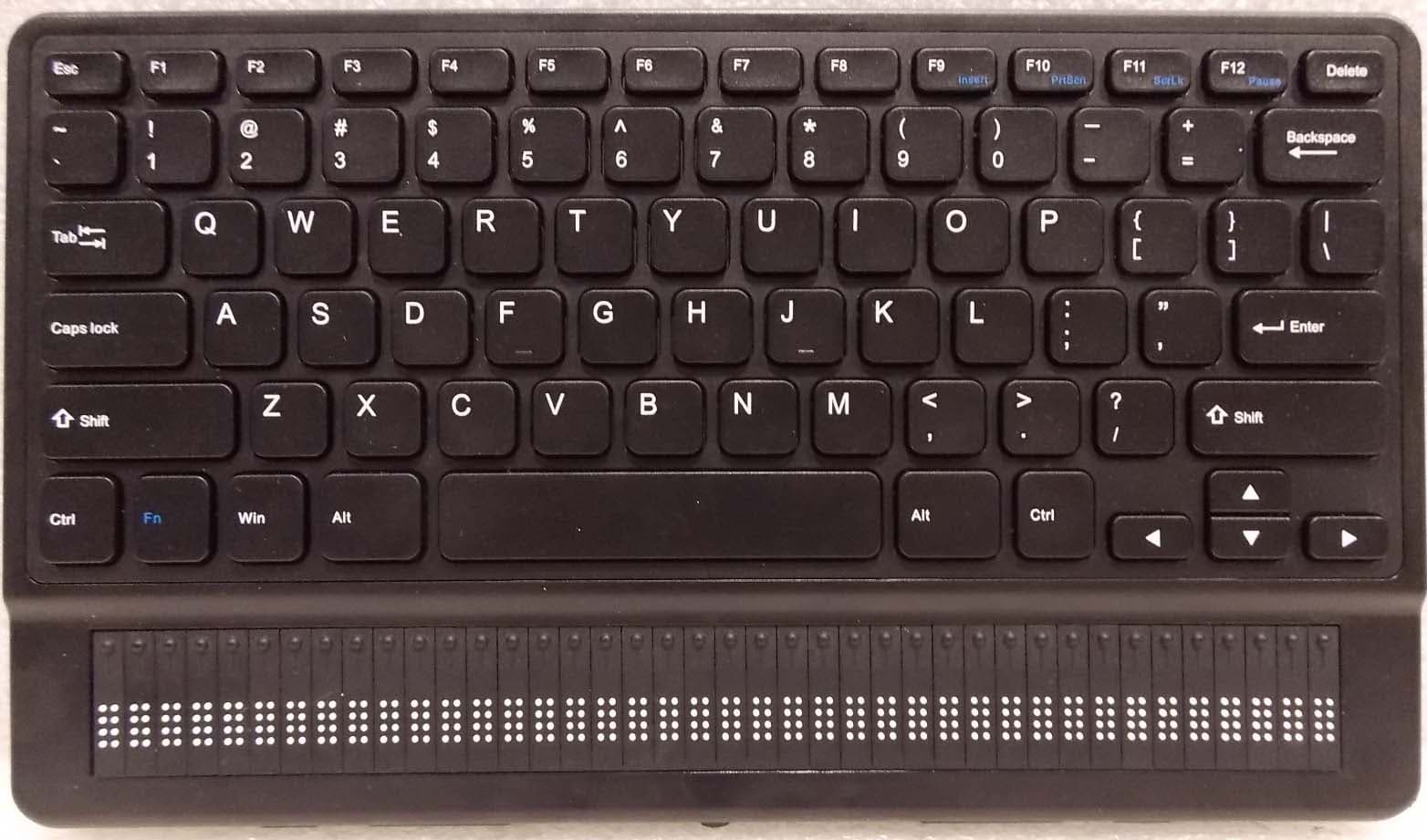
XT5-BRQT40
Jul 09, 2020braille notetaker and book reader
Equipment Class
DTS - Digital Transmission System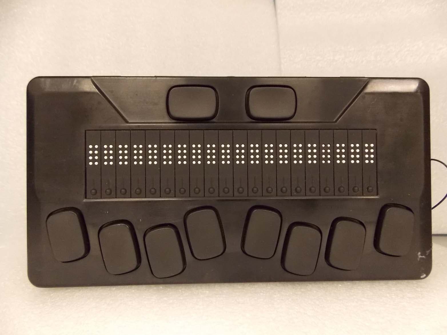
XT5-BR20
Apr 26, 2020braille notetaker and book reader
Equipment Class
DTS - Digital Transmission System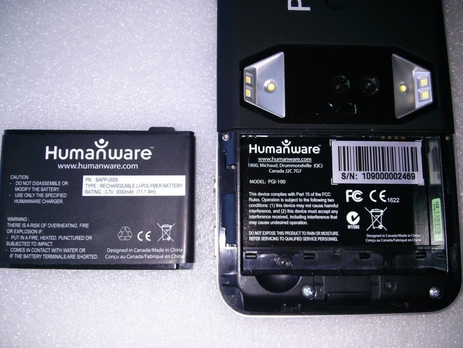
XT5PGITAB
Feb 11, 2015Modular video magnifier
Equipment Class
DTS - Digital Transmission System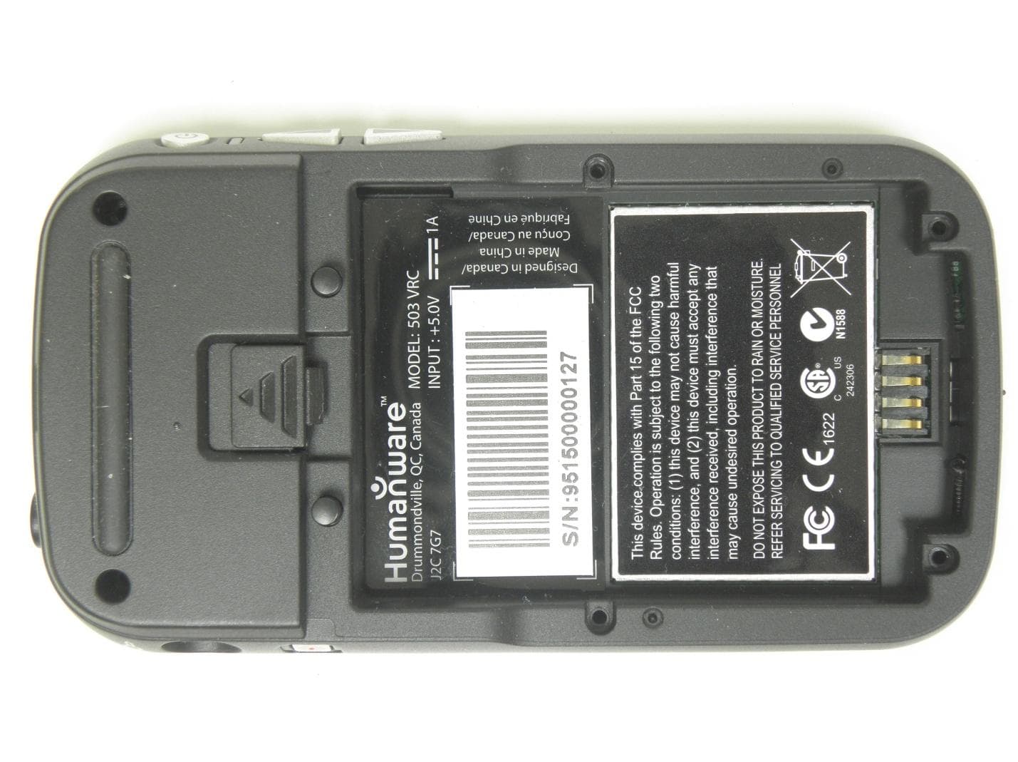
XT5503VRC
Nov 28, 2013Digital Talking book player
Equipment Class
DTS - Digital Transmission System
XT5APBT320
Apr 21, 2010Braille note taker and terminal
Equipment Class
DSS - Part 15 Spread Spectrum Transmitter