XYMBTSTVWS-1Base Station
Runcom Communications Ltd.
Click to zoom
Application Details
- Equipment Class
- WGF - White Space Device with Geo-location- Fixed
- Date of Grant
- Sep 10, 2015
- Application Purpose
- Original Equipment
- Date of Application
- Jul 13, 2015
- Equipment Note
- Base Station
- Frequency Range
- 473.00000000 - 695.00000000
- Company
- Runcom Communications Ltd.
- Country
- Israel
Documents & Files
Document Text
Text extracted from the exhibit documents filed with the FCC. Open a document above to read the original.
Users Manual
RNU4000BS User Manual Table of Contents Runcom Technologies Ltd. I , our product manager WiMAX RNU4000BS Base Station User Manual Doc: RUNCOM RNU4000BS USER MANUAL –RN–PMG-020615 V-4.1 Table of Contents RNU4000BS User Manual About this Guide This User Manual describes the procedures for commissioning, mounting, installing and managing the RNU4000BS Base Station. This base station comprises several base station types related to the frequency band. The base station is configured at the factory. For TVWS, this base is identified as RNU4000-TVWS. RNU4000-TVWS is designed to meet FCC Part 15 subpart H fixed device requirements. Notice This document contains proprietary and confidential material of Runcom Ltd. Any unauthorized reproduction, use or disclosure of this material, or any part thereof, is strictly prohibited. This document is solely for the use of Runcom Ltd. employees and authorized Runcom Ltd. customers. The material furnished in this document is believed to be accurate and reliable. However, no responsibility is assumed by Runcom Ltd. for the use of this material. Runcom Ltd. reserves the right to make changes to the material at any time and without notice. All other trademarks are the property of their respective owners. Other company and brand products and service names are trademarks or registered trademarks of their respective holders. Safety Precautions To avoid injury and to prevent equipment damage, observe the safety precautions below. • Only qualified personnel should be allowed to install, replace, and service the equipment. The device cannot be sold retail, to the general public or by mail order. It must be sold to dealers. Installation must be controlled. Installation must be performed by licensed professionals. Installation requires special training. The Runcom radios and antennas should be installed ONLY by experienced installation professionals who are familiar with local building and safety codes and, wherever applicable, are licensed by the appropriate government regulatory authorities. Failure to do so may void product warranty and may expose the end user or the service provider to legal and financial liabilities. • Always observe standard safety precautions during installation, operation and maintenance of this product. • This equipment must be installed according to country national electrical codes. • Any changes and modifications to the device and the accessories must be approved by Runcom. • All equipment and accessories must be installed in a restricted access area. • Observe all the labels on the equipment, providing operation details and warnings. • Read and follow the installation instructions provided in this manual. • The outdoor base station should be positioned more than 2 meters from humans. • In case of using cables that are not provided with the equipment package, ensure these cables comply with the regulatory inspection authorities and are the responsibility of the customer. • Do not move or ship equipment unless it is properly packed in its original wrapping and shipping containers. Electrical Shock Prevention • When connecting equipment to the AC and DC voltage supplies, ensure proper polarity. RNU4000BS Base Station User Manual שגיאה ! להחיל כדי בית בכרטיסיה השתמשHeading 1 כאן שיופיע שברצונך הטקסט על. • Disconnect the power source before installing or maintaining the power wiring. • Do not operate the equipment if there is any failure or damage to electrical components. • Do not touch exposed connections, components or wiring when power is on. • Install the equipment and the grounded DC supply circuits in adjacent cabinets. • Protect the DC power source with an adjacent circuit breaker. • The equipment must be properly grounded before attempting to operate or perform any repairs. RF Exposure To comply with FCC Section 1.310 for human exposure to radio frequency electromagnetic fields, implement the following instruction: A distance of at least 200cm between the equipment and all persons should be maintained during the operation of the equipment. Radio Interference This equipment generates and radiates radio frequency energy and if not installed and used in accordance with the instruction manual, may cause interference to radio communications. To avoid interferences: • Avoid conjunction with any other antenna or transmitter. • In case of Radio Interference: Relocate the antenna and Increase separation between the equipment and the receiver (e.g. connect to a separate circuit or outlet). • When using an external antenna, the external antenna must not be co-located or operating in conjunction with any other antenna or transmitter NOTE: This equipment has been tested and found to comply with the rules for TV bands devices, pursuant to part 15 of the FCC Rules. These limits are designed to provide reasonable protection against harmful interference in a residential installation. This equipment generates uses and can radiate radio frequency energy and, if not installed and used in accordance with the instructions, may cause harmful interference to radio communications. However, there is no guarantee that interference will not occur in a particular installation. If this equipment does cause harmful interference to radio or television reception, which can be determined by turning the equipment off and on, the user is encouraged to try to correct the interference by one or more of the following measures: -Reorient or relocate the receiving antenna. -Increase the separation between the equipment and receiver. -Connect the equipment into an outlet on a circuit different from that to which the receiver is connected. -Consult the dealer or an experienced radio/TV technician for help. Note: Contention Based Protocol (CBP) MUST be activated for the specified band (3.675-3.700GHz) wherever FCC rules and regulations are enforced. Failure to comply makes the operation of this device illegal. Table of Contents RNU4000BS User Manual NOTE: THE GRANTEE IS NOT RESPO…
Text truncated - open the document above for the full version.
Users Manual
Please contact us: Runcom Technologies Ltd. [email protected] Tel: +972-3-9428888 For more information on Runcom’s products see our website: www.runcom.com Information in this brochure might be changed without notice Basic Solution Specifications Number of sectors (BTS) 4 sectors with 1 antenna each or 1 sector with all antennas on it Frequency470-698MHz FFT512, 1024MHz** FECConvolution Code, Turbo Code and repetition Chan nel bandwidth 6MHz, 12MHz** Duplex methodTDD Central frequency Resolution 125 KHz Rx Sensitivity per channel -97 dBm @ 6MHz channel and QPSK1/2 modulation -89 dBm @ 6MHz channel and 16QAM 3⁄4 modulation Noise Figure<6dB Antennas (BTS) connector 4 x N-Type 50 Ohm Modu lation and coding rates DL/UL: QPSK (1/2, 3/4), 16 QAM (1/2, 3/4), 64 QAM (2/3, 3/4) Multiple antenna techniques DL: MIMO-A/B (2x2)**, STC, SISO Synchronization (BTS) Integrated GPS module with on board synchronization unit Capacity12Mbps(6MHz); 24Mbps(12MHz)** BTS Dimensions39cm (L) x 24cm (W) x 12cm (H) Weight5 KG Operating external temperature -40°C – 65°C industrial -10°C – 55°C commercial Physical Dimension (BTS) 4G End-to-End Mobile Solutions EquipmentNetwork/Antenna interface Antenna Mode Antennas gain TX PowerPower sourcePower consumption BTS / eBTS2xRJ-45 / N Type4TX, 4RX6dBi4x24dBm-48VDC65W Micro Noc2xRJ-45NANANA110-230Vac 12VDC 15W Outdoor CPEPOE RJ-45 / F Type2TX, 2RX2x12dBi or 2x7dBi 2x24dBiPOE 48VDC or 18VDC 5W AFA SRJ-45NANANA110-230VacNA BTS AntennaN TypePanel Antenna 6dBiNANA CPE AntennaF TypeYagi Antenna 10dBiNANANA Deliverables Network Management SNMPv2, standard and proprietary MIB System Configuration SNMP, FTP, CLI Software UpgradeRemote TFTP upgrade of firmware and programming FCC Data Base Management Using AFAS Software Management Frequency470-698 MHz BW6MHz, 12MHz Antennas 2 x external antenna connection IndicatorSignal strength, Data Power24 ± 1.5 dBm CPE* • ROI < 12 months • Better NLOS coverage than WiFi and LTE (3.65GHz) • Big Cells due to TVWS Frequencies • 470-698 MHz coverage • Enhanced Capacity using Channel bonding (24Mbps)** • 40 dBm EIRP** • 4 sectors in one unit • Affordable user terminals • Inherent redundancy using the terminals handoff feature • Special interference avoidance antenna * The CPE is pending FCC approval ** These features are pending FCC approval Government, Municipalities and Education Oil, Gas and Mining Data and Voice for Businesses and Private Networks and Residential Applications Homeland security, Emergency recovery, Public safety BETTER COVERAGE for Broadband Wireless Applications Video Surveillance and Traffic Control Emergency Services Utilities and Smart Grids WiFi Backhaul Internet of Things (IoT) RNU4000BS Scalable Deployment Entry into the 4G TV White Space broadband wireless access (TVWS-BWA) market encounters obstacles in the form of high costs, technical complexities and a shortage of resources. Runcom’s 4G Network solution for TV White Space provides seamles and cost-effective entry into the BWA – TVWS market for wireless telecom operators, wireless ISPs and system integrators. The TVWS 4G broadband access wireless solution includes a highly integrated, fully outdoor Runcom 4G enhanced Base Station with 4 sectors, various types of CPE units, a full network gateway and compact NOC towards the internet. The TVWS solution includes central or distributed service support for daily update of authorized frequencies, and frequency allocation according to the FCC regulations. All devices are provided with their mechanical installation kit, remote and local configuration capabilities, and user manuals. The TVWS 4G system is delivered as a ready to work plug-and-play system, making it possible for service providers to rollout an initial light weight and low-cost TVWS BWA fixed network in a matter of hours. Solution content Enhanced Base Station with 4 antennas (TX/RX), installation kit and power supply. Direct connection to the internet. Full site solution with 2,3 or 4 base stations, MicroNOC and frequency automated allocation server (AFAS). Automated frequency allocation server for daily update according to FCC regulations. Outdoor plug and play CPE with PoE, remote management and users behind CPE control. Immediate entry into the 4G TVWS wireless market QUAD Sector 4X4 Mode Dual Sector 2X2 Mode SISO Quad Sector 1x1 Mode RNU4000BS RNU4000BS RNU4000BS 3G Offload Rural, Urban, Sub-urban 4G TV White Space Solution Key Features Core components of the 4G TVWS advanced outdoor solutions: • M icroNOC: ASN gateway, Basic AAA, DHCP & DNS • 4G OFDMA Base Station with integrated 4 RF transceivers covering all TVWS spectrum (470-698MHz) • CPEs with multi user, multi service support • AFAS – Automated Frequency Allocation Server Complete network interface including AAA, routing, profile policing enforcement, and more Remote control and configuration to all network elements D aily frequency updates by the AFAS according to FCC requirements Supports full white space spectrum at all devices, in cluding channel bonding (12MHz).** Supports multiuser behind CPE, application awareness, QoS and more Synchronization circuit with GPS (internal or external) D esigned for light and easy installation in both urban and rural areas P lug-and-play – quick and easy-to-install Flexible base station installation – on rooftops, street, water tanks, grain elevators, poles or towers Seamless migration from single enhanced base station, through multiple base stations at a site to full-scale network with Runcom NOC Suitable for multiple applications (full tripleplay – Video, Voice, Data) Operational Benefits U nique, all-in-one solution Quick installation Low entry cost Adaptable to customer needs Suitable for fixed and mobile networks Applications Rural and suburban internet services for large area coverage Data and voice for businesses, private networks and residential applications Government, municipalities and education V ideo surveillance, public safety and traffic control Emerge…
Text truncated - open the document above for the full version.
Users Manual
, our product manager TVWS AFAS Operation manual Doc: Runcom AFAS User Operation Manual RN–PMG-011215 V-2.0 AFAS operation manual II Runcom Technologies Ltd. About this Document This document describes the AFAS (Advanced Frequency Allocation Software) element as part of the TV White Space solution, describes the interaction between each element of the entire solution to guaranty proper operation under the FCC requirements and describes in details the command and operation the AFAS unit Notice This document contains proprietary and confidential material of Runcom Ltd. Any unauthorized reproduction, use or disclosure of this material, or any part thereof, is strictly prohibited. This document is solely for the use of Runcom Ltd. employees and authorized Runcom Ltd. customers. The material furnished in this document is believed to be accurate and reliable. However, no responsibility is assumed by Runcom Ltd. for the use of this material. Runcom Ltd. reserves the right to make changes to the material at any time and without notice. All other trademarks are the property of their respective owners. Other company and brand products and service names are trademarks or registered trademarks of their respective holders. Note: THE AFAS SHALL BE OPERATED ONLY IN CONJUNCTION WITH THE SPECTRUM BRIDGE TVWS DATA BASE, THE RNU-4000TVWS Base Stations (FCC Identifier: XYMBSTVWS-1) AND THE RUNCOM CPE-O-R-WS (FCC Identifier: XYMCPETVWS-1) AFAS operation Manual Table of Contents Runcom Technologies Ltd. III Table of Contents 1 Introduction- TVWS Solution ........................................................................................... 1 1.1 Solution elements ....................................................................................................................... 2 1.1.1 AFAS ............................................................................................................................... 2 1.1.2 NOC (MicroNOC, Compact NOC) ...................................................................................... 2 1.1.3 Base Station ..................................................................................................................... 3 1.1.4 CPE ................................................................................................................................. 3 2 AFAS – Internal operation ................................................................................................ 4 2.1 Adding new Base Station (BS) ..................................................................................................... 4 2.2 Adding new CPE ........................................................................................................................ 5 2.3 Periodic update .......................................................................................................................... 6 3 AFAS – Configuration ...................................................................................................... 7 3.1 Home page ................................................................................................................................ 8 3.2 Add Base Station ...................................................................................................................... 10 3.3 View Registered Base Stations .................................................................................................. 15 3.4 View / Change Base Stations Information ................................................................................... 17 4 AFAS – Connection Status ............................................................................................ 20 4.1 FCC Database connection lost .................................................................................................. 20 5 Adding CPE to the AFAS ............................................................................................... 22 List of Figures and tables AFAS Operation manual IV Runcom Technologies Ltd. List of Figures: Figure 1: WIMAX TVWS core network diagram .......................................................................... 1 Figure 2 - Adding a new BS to the network ................................................................................ 4 Figure 3 - Adding a new CPE to the network ............................................................................. 5 Figure 4 - Periodic channels update ......................................................................................... 6 Figure 5: Hierarchy Leafing ...................................................................................................... 7 Figure 6: Home page .............................................................................................................. 8 Figure 7: management Administration Page .............................................................................. 9 Figure 8: Add Base Station - option 1 ..................................................................................... 10 Figure 9: Add Base Station - Option 2 ..................................................................................... 11 Figure 10: Add Base Station - option 3 .................................................................................... 11 Figure 11: Add base Station page 1- Device Information .......................................................... 12 Figure 12: Add Base Station page 2 – Contact Information ....................................................... 13 Figure 13: Add Base Station page 3 – Advanced Information .................................................... 14 Figure 14: Base Station Page Selection .................................................................................. 15 Figure 15: Registered Base Stations Information ..................................................................... 16 Figure 16: Base Station Information page 1- Device Information ............................…
Text truncated - open the document above for the full version.
Cover Letter(s)
June 2 nd , 2015 To Whom it May Concern Runcom TVWS Base Station RNU4000-TVWS 1. Runcom TVWS Base Station RNU4000-TVWS is part of a broadband wireless access solution that Runcom offers to its customers. 2. The purpose of Runcom TVWS solution is to provide Point-to- Multipoint Broadband Internet Access in rural areas. 3. The target customers for this product are Wireless Internet Service Providers (WISPs) in rural and remote areas that need to provide broadband Internet access to customers ( subscribers) that are beyond trees, hills and other obstacles that prevent from the classical Line of Sight ( LOS) wireless solutions to provide a reliable link. Yours sincerely, Israel Koffman Runcom CEO
Cover Letter(s)
–Runcom Proprietary and Confidential- Broadband Wireless Access Network Page 1 of 2 © 2009 Runcom Technologies Inc.-Confidential- October 5 th , 2015 To: FCC Laboratory Attn: Phillip Hardt Copy : ITL - David Shidlowsky; Timco – Sid Sanders; Runcom – Tzvi Marcu Clarification Letter Reference: FCC email from October 1 st 2015 regarding: Inconsistencies between marketing material and FCC application (Correspondence reference number: 214831). Attachment: TVWS Brochure 4GTVWS-2-1 Dear Sir, This letter is in response to the referenced correspondence regarding FCC ID: XYMBTSTVWS-1, APPLICANT: Runcom technologies Ltd., Form 731 Confirmation Number: TC656103 Runcom apologize for the mistake it did by distributing marketing material inconsistence with the FCC application. The mistake was caused by not clarifying in the brochure we used in the past that some new features that are in Runcom's roadmap are still FCC approval pending. Immediately after Runcom was aware of the problem, Runcom performed the following corrective actions: 1- Replaced the brochure with a brochure that is consistent with the FCC application ( see attached) 2- Stopped the distribution of the inconsistent brochure. 3- Informed all its distributors, resellers and representatives in the US to destroy the inconsistent brochure and use only the consistent brochure. Runcom can assure that no TVWS systems will be supplied to customers in the US that are inconsistent with the FCC application. In regards to the question about the TVWS CPE, Runcom can confirm the CPE is currently undergoing FCC testing at ITL Laboratories and the target is to complete the certification before end of 2015 (This fact is mentioned in the brochure as well). The CPE functions as a standard broadband wireless access terminals (TVWS adapted WiMAX technology), The CPE connects with the TVWS Data Base through the TVWS Base Station and the AFAS (Automatic Frequency –Runcom Proprietary and Confidential- Broadband Wireless Access Network Page 2 of 2 © 2009 Runcom Technologies Inc.-Confidential- Allocation Software) System. We are certain that the inconsistency problem is resolved and that this new TVWS solution will be able to provide reliable and affordable broadband connectivity to underserved residents in rural America that are waiting for such a solution. Runcom will be honored to provide any further clarifications if required. Sincerely, Israel Koffman CEO Direct Phone:+972-3-9428874 Office Phone:+972-3-9428888 Mobile Phone:+972-545-303110 Skype: Israel.Koffman FAX:+972-3-9528805
Operational Description
RF Unit description The RF unit contains 2 RF cards witch transmits and receives through 4 antennas. Each RF card supports 2 antennas, through 2 identical RF circuits. RF Circuit description For transmit pass, the RF IC converts digital data from WiMax modem to a 2345 MHz modulate analog signal. This analog signal goes into a down converter mixer that change between 1650-1872 MHz and its output, that is 470-698 MHz, gets into preliminary amplifier, final amplifier and then, through Tx / Rx switch and Low Pass Filter to the antenna. For receive pass, an analog signal at frequency between 470-698 MHz comes from antenna and through LPF and Tx / Rx switch, goes to LNA and then through HPF and LNA to an up converter mixer that change between 1650-1872 MHz and its output is 2345 MHz. This 2345 MHz signal goes into RF IC which converts it to digital signal and transfers it to WiMax modem.
Operational Description
ANT-O-TVWS-BTS-8 Antenna for TVWS Base Station Datasheet Version 1.0 Technical parameters Frequency range 470-700 MHz Bandwidth Broadband Polarization Vertical Connector N-type Maximum Power Handling Capability 10 W Gain (at mid band, ref. to λ/2 dipole) 8.0 dBi VSWR (in the whole band) < 1.8:1 Impedance 50 ohm Front to back ratio > 20 dB Cross Polarization Isolation > 24 dB Lightning Protection DC Grounded Elements Horizontal Beamwidth (at -3 dB, depends on frequency) 90° Vertical Beamwidth (at -3 dB, depends on frequency ) 35° - 21° About Runcom Runcom, the recognized pioneer of Orthogonal Frequency Division Multiple Access (OFDMA®) WiMAX technology, provides a range of advanced, simple to install, OFDMA-based WiMAX infrastructure equipment that complies with the IEEE802.16e-2005 standard for WiBro and Mobile WiMAX applications. The advanced, future-safe technologies embedded into Runcom products enable operators to get in on the ground floor - starting with either Fixed or Mobile WiMAX coverage and easily migrate to provide additional solutions as future opportunities arise. Runcom’s Modular and highly integrated products encourage scalable network deployment that significantly improves CAPEX and OPEX performance.
Parts List/Tune Up Info
Date:May 18, 2015 To: Federal Communications Commission Subject: FCC ID:XYMBTSTVWS-1Tune up procedure No manual tune-up procedure required. Thank you, Tzvi Marcu, Technical Support Manager
Test Report
Test Report E151900.02Runcom Technologies Ltd.Page 1 of 158 FCC ACC M Ver 1.2 28 February 2011 DATE: 06 July 2015 I.T.L. (PRODUCT TESTING) LTD. FCC Radio Test Report for Runcom Technologies Ltd. Equipment under test: Base Station RNU4000-TVWS (DSSS & OFDM) Tested by:_____________________________ I. Siboni Approved by: _____________________________ D. Shidlowsky This report must not be reproduced, except in full, without the written permission of I.T.L. (Product Testing) Ltd. This report relates only to items tested. Test Report E151900.02Runcom Technologies Ltd.Page 2 of 158 FCC ACC M Ver 1.2 28 February 2011 Measurement/Technical Report for Runcom Technologies Ltd. BaseStation RNU4000-TVWS FCC ID: XYMBTSTVWS-1 06 July 2015 This report concerns:Original Grant:X Class I Change: Class II Change: Equipment type:WGF - White Space Device with Geo-Location- Fixed Limits used:47CFR15 Section 15.709 Measurement procedure used is ANSI C63.4-2009 and KDB 416721 D01 White Space Test Procedure v02. Application for Certification Applicant for this device: prepared by:(different from "prepared by") R. PinchuckTzvi Marcu ITL (Product Testing) Ltd.Runcom Technologies Ltd. 1 Bat Sheva St.11 Moshe Levi Streeet Lod 7116002Rishon Le Zion 754658 IsraelTel:+972-3-942-8888 e-mail [email protected]:+972-3-952-8805 e-mail: [email protected] Test Report E151900.02Runcom Technologies Ltd.Page 3 of 158 FCC ACC M Ver 1.2 28 February 2011 TABLE OF CONTENTS 1. GENERAL INFORMATION ------------------------------------------------------------------------------- 5 1.1 Administrative Information.................................................................................5 1.2 List of Accreditations .........................................................................................6 1.3 Product Description ...........................................................................................7 1.4 Test Methodology ..............................................................................................7 1.5 Test Facility .......................................................................................................7 1.6 Measurement Uncertainty .................................................................................7 2. SYSTEM TEST CONFIGURATION--------------------------------------------------------------------- 8 2.1 Justification........................................................................................................8 2.2 EUT Exercise Software .....................................................................................8 2.3 Special Accessories ..........................................................................................8 2.4 Equipment Modifications ...................................................................................8 2.5 Configuration of Tested System ........................................................................9 3. RADIATED MEASUREMENT TEST SET-UP PHOTO -------------------------------------------10 4. BAND EDGE ------------------------------------------------------------------------------------------------12 4.1 Test Specification ............................................................................................12 4.2 Test Procedure ................................................................................................12 4.3 Test Results.....................................................................................................12 4.4 Test Equipment Used; Band Edge ..................................................................41 5. ADJACENT-CHANNEL-----------------------------------------------------------------------------------42 5.1 Test Specification ............................................................................................42 5.2 Test Procedure ................................................................................................42 5.3 Test Results.....................................................................................................42 6. MAXIMUM TRANSMITTED PEAK POWER OUTPUT -------------------------------------------84 6.1 Test Specification ............................................................................................84 6.2 Test Procedure ................................................................................................84 6.3 Test Results.....................................................................................................84 6.4 Test Equipment Used; Maximum Transmitted Peak Power Output..............108 7. POWER SPECTRAL DENSITY----------------------------------------------------------------------- 109 7.1 Specification ..................................................................................................109 7.2 Test Procedure ..............................................................................................109 7.3 Test Results...................................................................................................109 7.4 Test Equipment Used; Power Spectral Density ............................................131 8. CONDUCTED SPURIOUS EMISSIONS------------------------------------------------------------ 132 8.1 Specification ..................................................................................................132 8.2 Test Procedure ..............................................................................................132 8.3 Test Results...................................................................................................132 8.4 Test Equipment Used; Conducted Emission.................................................137 9. RADIATED EMISSION, 9 KHZ – 30 MHZ --------------------------------------------------------- 138 9.1 Test Specification ..........................................................................................138 9.2 Test Procedure .....................................................................................…
Text truncated - open the document above for the full version.
Test Report
Test Report E151900.02Runcom Technologies Ltd.Page 42 of 158 FCC ACC M Ver 1.2 28 February 2011 5.Adjacent-Channel 5.1Test Specification FCC Part 15, Subpart H, Section 15.709(c)(2) 5.2Test Procedure The E.U.T operation mode and test set-up are as described in Section 2. See Section 2.1 Justification of the System Test Configuration concerning the E.U.T. orientation for this test. The E.U.T. antenna terminal was connected to…
Text truncated - open the document above for the full version.
Contact Information
Applicant
Israel Koffman(CEO)
Test Firm
Israel Testing LaboratoriesIIan Cohen
Technical Specifications
| # | Rule Parts | Frequency Range | Power Output |
|---|---|---|---|
| 1 | 15H | 473 MHz - 695 MHz | 340.00 mW |
Other Applications from Runcom Communications Ltd.
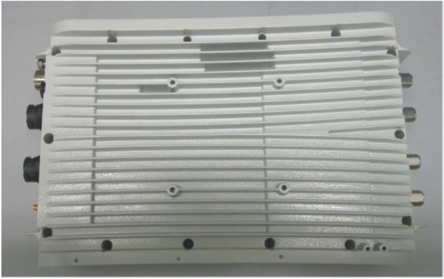
XYMPICO4A701WDC
Mar 11, 2013Pico Base station
Equipment Class
TNB - Licensed Non-Broadcast Station Transmitter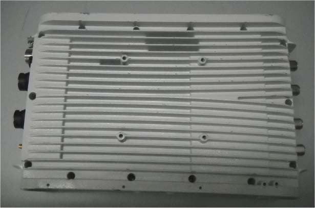
XYMPICO4A351WDC
Nov 08, 2012Pico Base station
Equipment Class
TNB - Licensed Non-Broadcast Station Transmitter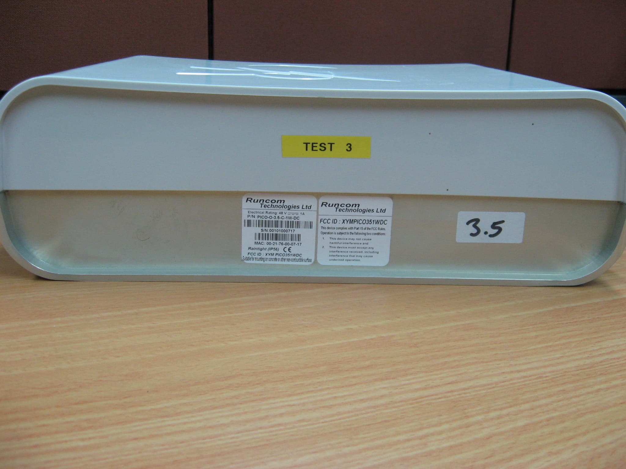
XYMPICO351WDC
Aug 15, 2010OUTDOOR PICO BASE STATION 3.5 GHz
Equipment Class
TNB - Licensed Non-Broadcast Station Transmitter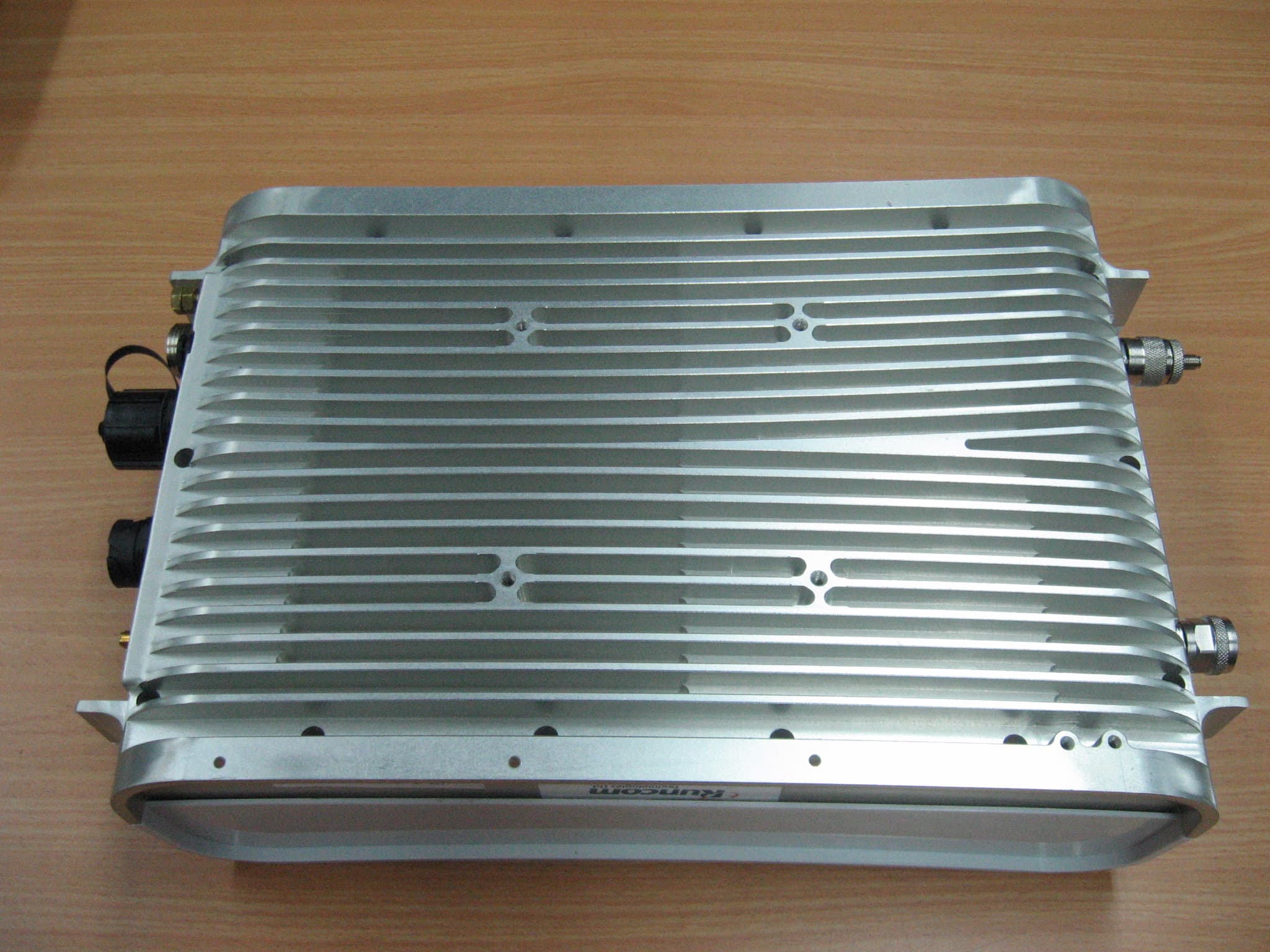
XYMPICO251WDC
Jan 17, 2010OUTDOOR PICO BASE STATION 2.5 GHz
Equipment Class
TNB - Licensed Non-Broadcast Station Transmitter