XYMPICO251WDCOUTDOOR PICO BASE STATION 2.5 GHz
Runcom Communications Ltd.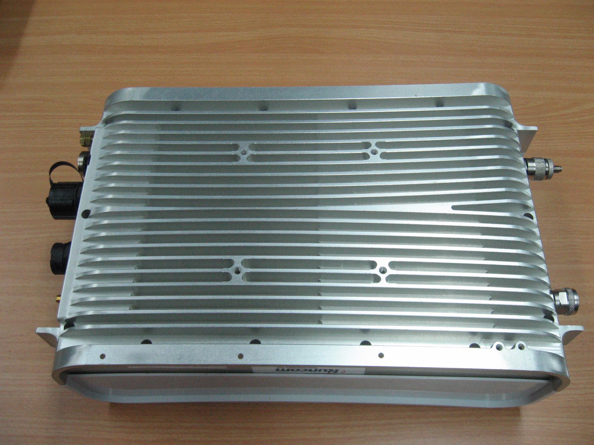
Click to zoom
Application Details
- Equipment Class
- TNB - Licensed Non-Broadcast Station Transmitter
- Date of Grant
- Jan 17, 2010
- Application Purpose
- Original Equipment
- Date of Application
- Jan 13, 2010
- Equipment Note
- OUTDOOR PICO BASE STATION 2.5 GHz
- Frequency Range
- 2501.00000000 - 2685.00000000
- Company
- Runcom Communications Ltd.
- Country
- Israel
Documents & Files
Document Text
Text extracted from the exhibit documents filed with the FCC. Open a document above to read the original.
Users Manual
CONFIDENTIAL WiMAX PicoPlus Base Station User Manual Doc No.: PPBS_UM 6-JAN-10 REV-02 Preface Material PicoPlus Base Station User Manual II CONFIDENTIAL Runcom Technologies Ltd. About this Guide This User Manual describes the procedures for commissioning, mounting, installing and managing the PicoPlus Base Station. Notice This document contains proprietary and confidential material of Runcom Ltd. Any unauthorized reproduction, use or disclosure of this material, or any part thereof, is strictly prohibited. This document is solely for the use of Runcom Ltd. employees and authorized Runcom Ltd. customers. The material furnished in this document is believed to be accurate and reliable. However, no responsibility is assumed by Runcom Ltd. for the use of this material. Runcom Ltd. reserves the right to make changes to the material at any time and without notice. All other trademarks are the property of their respective owners. Other company and brand products and service names are trademarks or registered trademarks of their respective holders. Revision History Date Author Description Revision AUG 2009 tothepoint Initial A0 Safety Precautions To avoid injury and to prevent equipment damage, observe the safety precautions below. • Outdoor installation procedures should be performed by quality professionals following all safety and the other requirements and acting in accordance with standard practices and procedures. Failure to meet safety requirements and/or non-standard practices and procedures could result in personal injury and/or damage to equipment. • Always observe standard safety precautions during installation, operation and maintenance of this product. • This equipment must be installed according to country national electrical codes. • Any changes and modifications to the device and the accessories must be approved by Runcom. • All equipment and accessories must be installed in a restricted access area. • Observe all the labels on the equipment, providing operation details and warnings. • Read and follow the installation instructions provided in this manual. • In case of using cables that are not provided with the equipment package, ensure these cables comply with the regulatory inspection authorities and are the responsibility of the customer. • Do not move or ship equipment unless it is properly packed in its original wrapping and shipping containers. Electrical Shock Prevention • When connecting equipment to the AC and DC voltage supplies, ensure proper polarity. • Disconnect the power source before installing or maintaining the power wiring. PicoPlus Base Station User Manual Preface Material Runcom Technologies Ltd. CONFIDENTIAL III • Do not operate the equipment if there is any failure or damage to electrical components. • Do not touch exposed connections, components or wiring when power is on. • Install the equipment and the grounded DC supply circuits in adjacent cabinets. • Protect the DC power source with an adjacent circuit breaker. • The equipment must be properly grounded before attempting to operate or perform any repairs. RF Exposure To avoid RF exposure - Installation of antennas must comply with the FCC RF exposure requirements. Radio Interference This equipment generates and radiates radio frequency energy and if not installed and used in accordance with the instruction manual, may cause interference to radio communications. To avoid interferences: • Avoid conjunction with any other antenna or transmitter. • In case of Radio Interference: Relocate the antenna and Increase separation between the equipment and the receiver (e.g. connect to a separate circuit or outlet). FCC General: This equipment has been tested and found to comply with the limits for a Class B digital device, pursuant to Part 15 of the FCC rules. These limits are designed to provide reasonable protection against harmful interference in a residential installation. This equipment generates uses and can radiate radio frequency energy and, if not installed and used in accordance with the instructions, may cause harmful interference to radio communications. However, there is no guarantee that interference will not occur in a particular installation. If this equipment does cause harmful interference to radio or television reception, which can be determined by turning the equipment off and on, the user is encouraged to try to correct the interference by one or more of the following measures: a) Reorient or relocate the receiving antenna. b) Increase the separation between the equipment and receiver. c) Connect the equipment to an outlet on a circuit different from that to which the receiver is connected. d) Consult the dealer or an experienced radio/TV technician. Warning: Modifications not expressly approved by the manufacturer could void the user authority to operate the equipment under FCC Rules Preface Material PicoPlus Base Station User Manual IV CONFIDENTIAL Runcom Technologies Ltd. Installation Rules: 1. Unit is intended for installation in Restricted Access Location only. 2. Unit shall be installed on/above concrete or other non combustible surface only. 3. The minimum distance between the BS antennas and the public zone is at least 1 meter 4. The unit shall be installed at least 5 meters above the ground level 5. When unit is installed outdoors length of exposed outdoor wiring shall not exceed 130ft (46meters) 6. Unit earthing screw terminal shall be permanently connected to protective earth in building installation in accordance with applicable national code and regulations. 7. The screen of the coaxial cables (connections to outdoor antennas) shall be permanently connected to protective earth in building installation. 8. In Finland, Norway and Sweden unit shall be installed in a Restricted Access Location where equipotential bonding has been applied (e.g. telecommunication center). 9. Unit power line 48VDC shall be protected by 2-pole circuit breaker, suitably certified in accordance with applica…
Text truncated - open the document above for the full version.
Operational Description
Operational description Upon power‐up of the Outdoor Pico Base Station, a loader application (burned in FLASH and different then the SW application) launches the SW application. The Application initializes its internal modules and waits for a command to activate WiMAX activity. Command is sent via servers or manually. Upon command the downlink and uplink is activated and the Base Station is ready to serve the end users.
RF Exposure Info
R.F Exposure/Safety Calculation Outdoor Pico Base Station 2.5 GHz Calculation of Maximum Permissible Exposure (MPE) Based on Section 1.1307(b)(1) Requirements 2 1 cm mW (a) FCC limits at 2600 MHz is: Using table 1 of Section 1.1310 limit for general population/uncontrolled exposures, the above level is an average over 30 minutes. (b) The power density produced by the E.U.T. is 2 4R GP S tt π = π4 tt GP R= P - Transmitted Power 35.2dBm = 3311.3mW t G T - Antenna Gain 15dBi = 31.6 R- Distance from Transmitter S- MPE=1 (c) The calculated minimum distance between the EUT antenna and the general public is : cmR3.91 4 6.313.3311 = × = π (d) According to the customer the minimum distance between the EUT antenna and the general public is 1 meter.
Test Report
Test Report E93100.00 Runcom Technologies Ltd. Page 1 of 187 FCC ACC M Ver 1.1 05Mayl 2000 DATE: 31 December 2009 I.T.L. (PRODUCT TESTING) LTD. FCC Radio Test Report for Runcom Technologies Ltd. Equipment under test: WiMAX Base Station Outdoor Pico Base Station 2.5 GHz Written by: _____________________________ D. Shidlowsky, Documentation Approved by: _____________________________ A. Sharabi, Test Engineer Approved by: _____________________________ I. Raz, EMC Laboratory Manager This report must not be reproduced, except in full, without the written permission of I.T.L. (Product Testing) Ltd. This report relates only to items tested. Test Report E93100.00 Runcom Technologies Ltd. Page 2 of 187 FCC ACC M Ver 1.1 05Mayl 2000 Measurement/Technical Report for Runcom Technologies Ltd. WiMAX Base Station Outdoor Pico Base Station 2.5 GHz FCC ID: XYMPICO251WDC This report concerns: Original Grant: X Class II change: Class I change: Equipment type: Licensed Non-Broadcast Transmitter Limits used: 47CFR Part 27 Measurement procedure used is ANSI C63.4-2003. Substitution Method used as in ANSI/TIA-603-B: 2002 Application for Certification Applicant for this device: prepared by: (different from "prepared by") Ishaishou Raz Ronen Greenberg ITL (Product Testing) Ltd. Runcom Technologies Ltd. Kfar Bin Nun 11 Moshe Levi St. D.N. Shimshon 99780 Rishon Le Zion 75658 Israel Israel e-mail [email protected] Tel: +972-3-952-8440 Fax: +972-3-952-8805 e-mail: [email protected] TABLE OF CONTENTS 1. GENERAL INFORMATION ------------------------------------------------------------------------------- 5 1.1 Administrative Information ................................................................................. 5 1.2 List of Accreditations ......................................................................................... 6 1.3 Product Description ........................................................................................... 7 1.4 Test Methodology .............................................................................................. 7 1.5 Test Facility ....................................................................................................... 7 1.6 Measurement Uncertainty ................................................................................. 8 2. SYSTEM TEST CONFIGURATION --------------------------------------------------------------------- 9 2.1 Justification ........................................................................................................ 9 2.2 EUT Exercise Software ..................................................................................... 9 2.3 Special Accessories .......................................................................................... 9 2.4 Equipment Modifications ................................................................................... 9 2.5 Configuration of Tested System ...................................................................... 10 3. TEST SET-UP PHOTOS ----------------------------------------------------------------------------------11 4. CONDUCTED EMISSION DATA -----------------------------------------------------------------------13 5. MAXIMUM PEAK OUTPUT POWER 5 MHZ BANDWIDTH ------------------------------------19 5.1 Test Specification ............................................................................................ 19 5.2 Test procedure ................................................................................................ 19 5.3 Results table .................................................................................................... 25 5.4 Test Equipment Used. ..................................................................................... 26 6. MAXIMUM PEAK OUTPUT POWER 10 MHZ BANDWIDTH -----------------------------------27 6.1 Test Specification ............................................................................................ 27 6.2 Test procedure ................................................................................................ 27 6.3 Results table .................................................................................................... 33 6.4 Test Equipment Used. ..................................................................................... 34 7. SPECTRAL POWER DENSITY 5 MHZ BANDWIDTH -------------------------------------------35 7.1 Test Specification ............................................................................................ 35 7.2 Test procedure ................................................................................................ 35 7.3 Results table .................................................................................................... 41 7.4 Test Equipment Used. ..................................................................................... 42 8. SPECTRAL POWER DENSITY 10 MHZ BANDWIDTH ------------------------------------------43 8.1 Test Specification ............................................................................................ 43 8.2 Test procedure ................................................................................................ 43 8.3 Results table .................................................................................................... 49 8.4 Test Equipment Used. ..................................................................................... 50 9. OCCUPIED BANDWIDTH 5 MHZ BANDWIDTH --------------------------------------------------51 9.1 Test Specification ............................................................................................ 51 9.2 Test Procedure ................................................................................................ 51 9.3 Results Table .................................................................................................. 56 9.4 Test Equipment Used. ..................................................................................... 57 10.…
Text truncated - open the document above for the full version.
Contact Information
Applicant
Israel Koffman(CEO)
Test Firm
Israel Testing LaboratoriesIIan Cohen
Technical Specifications
| # | Rule Parts | Frequency Range | Power Output | Emission | Tolerance |
|---|---|---|---|---|---|
| 2 | 27 | 2.50 GHz - 2.69 GHz | 2.09 W | 10M0D7D | 2.5 ppm |
Other Applications from Runcom Communications Ltd.

XYMBTSTVWS-1
Sep 10, 2015Base Station
Equipment Class
WGF - White Space Device with Geo-location- Fixed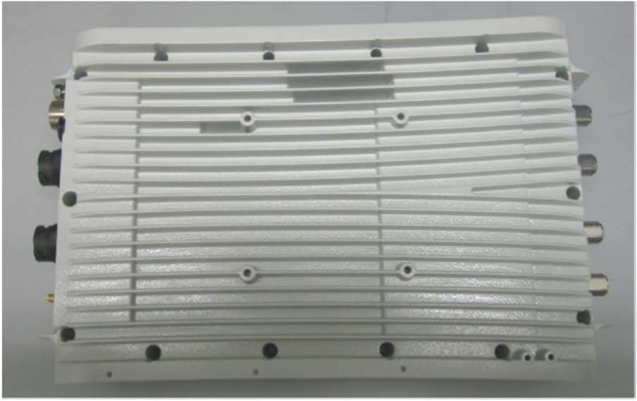
XYMPICO4A701WDC
Mar 11, 2013Pico Base station
Equipment Class
TNB - Licensed Non-Broadcast Station Transmitter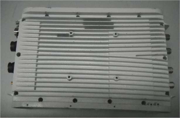
XYMPICO4A351WDC
Nov 08, 2012Pico Base station
Equipment Class
TNB - Licensed Non-Broadcast Station Transmitter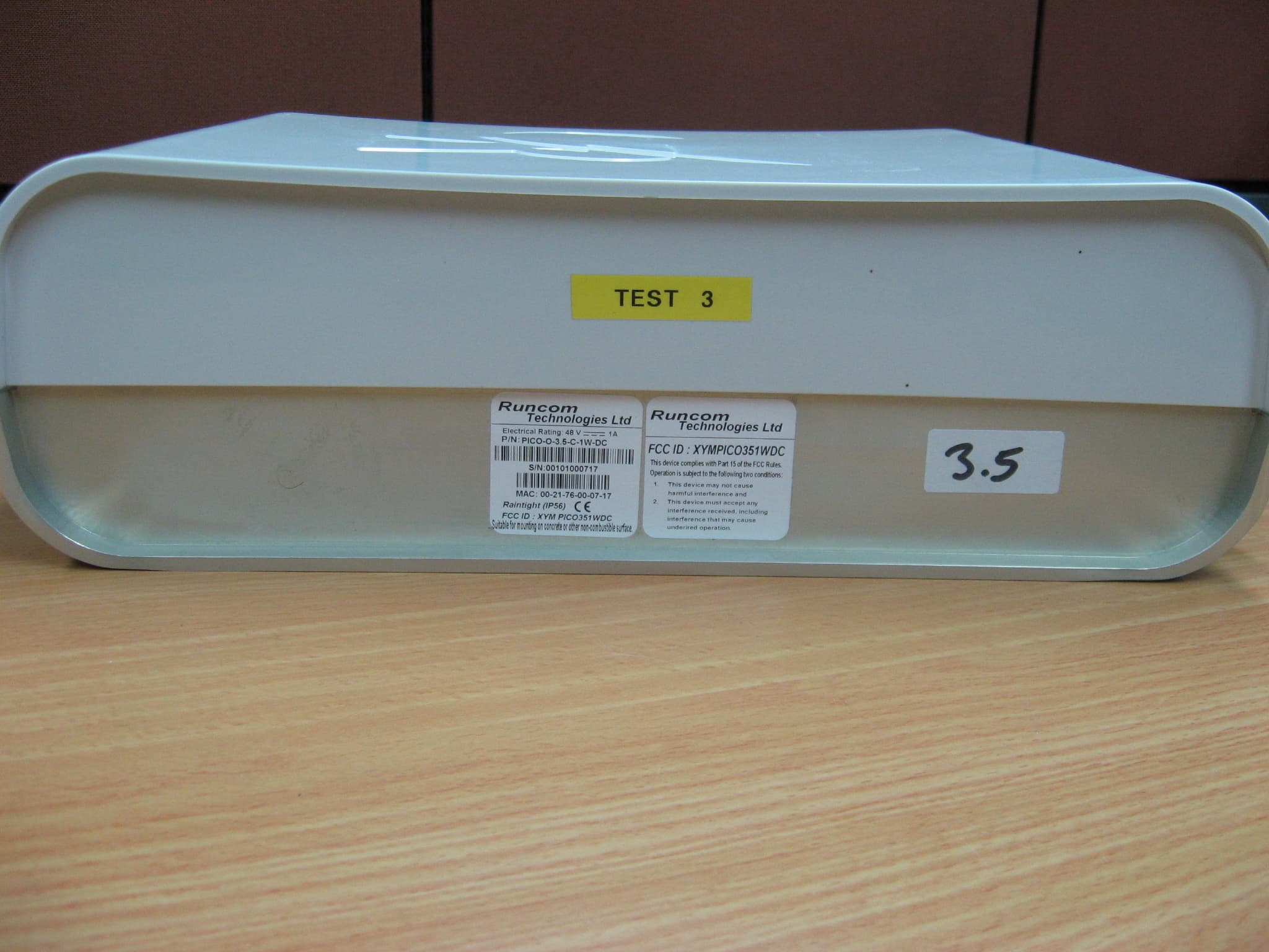
XYMPICO351WDC
Aug 15, 2010OUTDOOR PICO BASE STATION 3.5 GHz
Equipment Class
TNB - Licensed Non-Broadcast Station Transmitter