XYN2738Remote Control 2.4 GHz
ruwido austria GmbH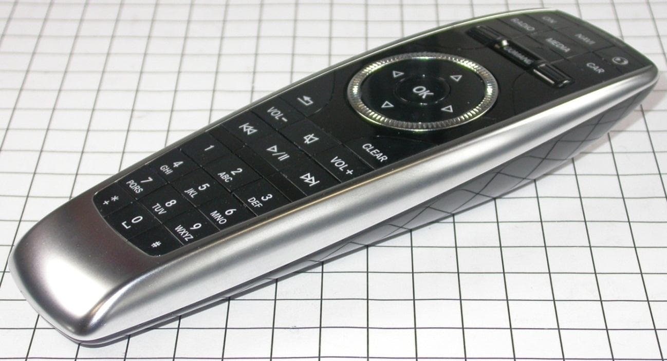
Click to zoom
Application Details
- Equipment Class
- DXX - Part 15 Low Power Communication Device Transmitter
- Date of Grant
- Dec 20, 2012
- Application Purpose
- Original Equipment
- Date of Application
- Dec 19, 2012
- Equipment Note
- Remote Control 2.4 GHz
- Frequency Range
- 2403.00000000 - 2478.00000000
- Company
- ruwido austria GmbH
- Country
- Austria
Documents & Files
Document Text
Text extracted from the exhibit documents filed with the FCC. Open a document above to read the original.
Users Manual
ruwido austria Gmbh Köstendorfer Straße 8 A-5202 Neumarkt a.W. Austria Telephone: +43(0)6216-4571 www.ruwido.com DAIMLER REMOTE CONTROL USER MANUAL Model 2738-xxx Documentstatus: Open Editor: Thomas Fischer Document Title: Daimler Remote Control User Manual 28.08.2011 ruwido austria GmbH UserManual.doc 2/4 i. Revision Status Version Date Author Comment 1.0 20.08.2012 Th. Fischer Created Document Title: Daimler Remote Control User Manual 28.08.2011 ruwido austria GmbH UserManual.doc 3/4 1 Table of Contents i. Revision Status ................................................................................................................................ 2 1 Table of contents .............................................................................................................................. 3 2 About this document ......................................................................................................................... 4 3 Startup .............................................................................................................................................. 4 4 Association ....................................................................................................................................... 4 5 Transmitting data .............................................................................................................................. 4 Document Title: Daimler Remote Control User Manual 28.08.2011 ruwido austria GmbH UserManual.doc 4/4 2 About this document The following document describes the use of the remote control model 2738. 3 Startup The remote control is battery operated. Please insert two fresh AAA batteries in the battery compartment on the back side of the remote. The indication LED above the mode wheel indicates the battery status after each button press. If the LED blinks red after a button press the batteries should be replaced. 4 Association To associate the remote with the receiving unit the buttons “ON” and “#” should be pressed simultaneously while the receiving unit is also in association mode. The indication LED blinks red during the association process and then blinks green when the association has finished successfully. If the association is not successful after 30 sec. the association process stops and the red indication LED stops blinking. 5 Transmitting data After the association process has finished successfully the remote control send data after each button press and while turning the navigation wheel. A successful transmission is indicated by the green indication LED. An unsuccessful transmission is indicated by the orange indication LED. Turning the mode wheel changes the mode in which the remote works; it does not send any data.
Cover Letter(s)
Request for Confidentiality Date: 18.12.2012 Subject: Confidentiality Request for: FCC ID:XYN2738 IC:8748A-2738 ______ Pursuant to FCC 47 CRF 0.457(d) and 0.459 and IC RSP-100, Section 10, the applicant requests that a part of the subject FCC application be held confidential. Type of Confidentiality Requested Exhibit Short Term Permanent Block Diagrams Short Term External Photos Short Term Permanent* 1 Internal Photos Short Term Permanent Operation Description/Theory of Operation Short Term Permanent Parts List & Placement/BOM Short Term Permanent Tune-Up Procedure Short Term Permanent Schematics Short Term Test Setup Photos Short Term Permanent* User’s Manual *Note: ______(Insert Explanation as Necessary)______ Ruwido austria gmbh has spent substantial effort in developing this product and it is one of the first of its kind in industry. Having the subject information easily available to "competition" would negate the advantage they have achieved by developing this product. Not protecting the details of the design will result in financial hardship. Permanent Confidentiality: The applicant requests the exhibits listed above as permanently confidential be permanently withheld from public review due to materials that contain trade secrets and proprietary information not customarily released to the public. Short-Term Confidentiality: The applicant requests the exhibits selected above as short term confidential be withheld from public view for a period of (0) days from the date of the Grant of Equipment Authorization and prior to marketing. This is to avoid premature release of sensitive information prior to marketing or release of the product to the public. Applicant is also aware that they are responsible to notify ACB in the event information regarding the product or the product is made available to the public. ACB will then release the documents listed above for public disclosure pursuant to FCC Public Notice DA 04-1705. NOTE for Industry Canada Applications: The applicant understands that until such time that IC distinguishes between Short Term and Permanent Confidentiality, either type of marked exhibit above will simply be marked Confidential when submitted to IC. Sincerely, By: Manager Certification Thomas Ring 1 - The asterisked items (*) require further justification before permanent confidentiality will be allowed. These also currently require review by the FCC under their Permit-But-Ask policy before the grant is issued and can delay completion of an application. Further justification should be added to the note above. One such example for a potted device would be: “The EUT is FULLY potted using a non-removable epoxy based material. Removal of potting material causes irreparable damage to internal circuitry. See photographs exhibits that outline the device before and after potting.”
External Photos
FCC ID: XYN2738 IC: 8748A-2738 mikes-testingpartners gmbh Ohmstrasse 2-4 94342 STRASSKIRCHEN GERMANY Tel.:+49(0)9424-94810 Fax:+49(0)9424-9481240 Rev. No. 1.2, 9.9.2010 3 E Q U I P M E N T U N D E R T E S T 3.1 Photo documentation of the EUT – Internal photos see attachment A
ID Label/Location Info
Christa Jäger Project Specialist - Global Market Access (GMA) / Certification mikes-testingpartners gmbh 94342 Strasskirchen Germany FCC ID no. XYN2738 for remote control Dear Sirs, Our customer has decided to not put the FCC ID on the outside of the device. It will be placed inside the battery compartment in accordance to the FCC requirements. Please see our explanation below: As an option to placing the FCC label on the exterior of the device, the FCC label may be placed in a user accessible area if the following conditions are met: • The device is handheld (notebook computers are considered as handheld); The device is handheld. • The FCC identifier is visible at the time of purchase. Marketing the device without the battery installed when the label is in the battery compartment is acceptable. The FCC ID on the box, or additional documentation directing the user where to find the FCC label, also satisfies this requirement; The FCC ID, IC certification number and model number are inside the battery compartment and the battery is not installed when the device is marketed. Additionally, the user manual directs the user where to find the FCC ID, IC certification number and model number within the battery compartment. • The user accessible area must not require any special tools for access, and the FCC label must not be placed on a removable part; The battery compartment does not require special tools. The FCC ID, IC certification number and model number are not on a removable part. • The FCC ID, Model Number, or FCC logo must be on the label and must meet all general labelling requirements or policies that apply for Certification, Verification or DoC. The FCC ID, IC certification number and model number do meet the applicable labelling requirements. Best regards, Rafael Jaburek Head of Quality ruwido austria gmbh Köstendorfer Straße 8 5202 Neumarkt a. W. Austria
Internal Photos
FCC ID: XYN2738 IC: 8748A-2738 mikes-testingpartners gmbh File No. T36144-00-02KJ, page 29 of 31 Ohmstrasse 2-4 94342 STRASSKIRCHEN GERMANY Tel.:+49(0)9424-94810 Fax:+49(0)9424-9481240 Rev. No. 1.2, 9.9.2010 7 A t t a c h m e n t A – I n t e r n a l p h o t o s FCC ID: XYN2738 IC: 8748A-2738 mikes-testingpartners gmbh File No. T36144-00-02KJ, page 30 of 31 Ohmstrasse 2-4 94342 STRASSKIRCHEN GERMANY Tel.:+49(0)9424-94810 Fax:+49(0)9424-9481240 Rev. No. 1.2, 9.9.2010 FCC ID: XYN2738 IC: 8748A-2738 mikes-testingpartners gmbh File No. T36144-00-02KJ, page 31 of 31 Ohmstrasse 2-4 94342 STRASSKIRCHEN GERMANY Tel.:+49(0)9424-94810 Fax:+49(0)9424-9481240 Rev. No. 1.2, 9.9.2010
Test Report
FCC ID: XYN2738 IC: 8748A-2738 mikes-testingpartners gmbh File No. T36144-00-02KJ, page 1 of 31 Ohmstrasse 2-4 94342 STRASSKIRCHEN GERMANY Tel.:+49(0)9424-94810 Fax:+49(0)9424-9481240 Rev. No. 1.2, 9.9.2010 EMI − T E S T R E P O R T - FCC Part 15.249 - Test Report No. : T36144-00-02KJ 18. December 2012 ______________________________________________________________________________________________ Date of issue Type / Model Name : 2738 Product Description : Remote Control 2.4 GHz Applicant : ruwido austria gmbh Address : Koestendorfer Str. 8 5202 NEUMARKT, AUSTRIA Manufacturer : ruwido austria gmbh Address : Koestendorfer Str. 8 5202 NEUMARKT, AUSTRIA Licence holder : ruwido austria gmbh Address : Koestendorfer Str. 8 5202 NEUMARKT, AUSTRIA Test Result according to the standards listed in clause 1 test standards: POSITIVE The test report merely corresponds to the test sample. It is not permitted to copy extracts of these test results without the written permission of the test laboratory. FCC ID: XYN2738 IC: 8748A-2738 mikes-testingpartners gmbh File No. T36144-00-02KJ, page 2 of 31 Ohmstrasse 2-4 94342 STRASSKIRCHEN GERMANY Tel.:+49(0)9424-94810 Fax:+49(0)9424-9481240 Rev. No. 1.2, 9.9.2010 Contents 1 T E S T S T A N D A R D S 3 2 S U M M A R Y 3 2.1 Test result summary 3 2.2 GENERAL REMARKS: 4 2.3 FINAL ASSESSMENT: 4 3 E Q U I P M E N T U N D E R T E S T 5 3.1 Photo documentation of the EUT – Internal photos see attachment A 5 3.2 Photo of the test setup 7 3.3 Power supply system utilised 9 3.4 Short description of the equipment under test (EUT) 9 4 T E S T E N V I R O N M E N T 10 4.1 Address of the test laboratory 10 4.2 Environmental conditions 10 4.3 Statement of the measurement uncertainty 10 4.4 Measurement protocol for FCC 11 5 T E S T C O N D I T I O N S A N D R E S U L T S 13 5.1 Conducted emissions 13 5.2 Radiated emission of the fundamental wave 14 5.3 Spurious emissions radiated 16 5.4 20 dB bandwidth 20 5.5 Correction for pulse operation (duty cycle) 23 5.6 Antenna application 25 5.7 Receiver radiated emissions 26 6 U S E D T E S T E Q U I P M E N T A N D A C C E S S O R I E S 28 7 A t t a c h m e n t A – I n t e r n a l p h o t o s 29 FCC ID: XYN2738 IC: 8748A-2738 mikes-testingpartners gmbh File No. T36144-00-02KJ, page 3 of 31 Ohmstrasse 2-4 94342 STRASSKIRCHEN GERMANY Tel.:+49(0)9424-94810 Fax:+49(0)9424-9481240 Rev. No. 1.2, 9.9.2010 1 T E S T S T A N D A R D S The tests were performed according to following standards: FCC Rules and Regulations Part 15, Subpart A - General (September, 2011) Part 15, Subpart A, Section 15.31 Measurement standards Part 15, Subpart A, Section 15.33 Frequency range of radiated measurements Part 15, Subpart A, Section 15.35 Measurement detector functions and bandwidths FCC Rules and Regulations Part 15, Subpart C - Intentional Radiators (September, 2011) Part 15, Subpart C, Section 15.203 Antenna requirement Part 15, Subpart C, Section 15.205 Restricted bands of operation Part 15, Subpart C, Section 15.209 Radiated emission limits, general requirements Part 15, Subpart C, Section 15.249 Operation within the bands 902 - 928 MHz, 2400 - 2483.5 MHz, 5725 - 5875 MHz, and 24.0 - 24.25 GHz ANSI C63.4: 2009 Methods of Measurement of Radio-Noise Emissions from Low- Voltage Electrical and Electronic Equipment in the Range of 9 kHz to 40 GHz. CISPR 16-4-2: 2003 Uncertainty in EMC measurement CISPR 22: 2005 Information technology equipment EN 55022: 2006 2 S U M M A R Y 2.1 Test result summary Operating in the 2400 MHz – 2483.5 MHz band: FCC Rule Part RSS Rule Part Description Result 15.207(a) RSS Gen, 7.2.4 Conducted limits not applicable 15.249(a)(e) RSS210, A8.2(b) Field strength of fundamental passed 15.249 (d) RSS-210, A8.5 Field strength of harmonics passed 15.209 (a) RSS-Gen, 7.2.5 Radiated emission limits passed 15.215 (c) RSS-210, A8.1(a) 20 dB bandwith passed 15.35 (c) RSS-Gen, 4.5 Duty cycle correction passed 15.203 (a) RSS-Gen, 7.1.2 Antenna application passed 15.109 (a) RSS-Gen, 6.1 Receiver radiated emissions passed The mentioned RSS Rule Parts in the above table are related to: RSS Gen, Issue 3, December 2010 RSS 210, Issue 8, December 2010 RSS 102, Issue 4, March 2010 FCC ID: XYN2738 IC: 8748A-2738 mikes-testingpartners gmbh File No. T36144-00-02KJ, page 4 of 31 Ohmstrasse 2-4 94342 STRASSKIRCHEN GERMANY Tel.:+49(0)9424-94810 Fax:+49(0)9424-9481240 Rev. No. 1.2, 9.9.2010 2.2 GENERAL REMARKS: The EUT uses a KLR3012A Kleer® technology chip which is designed for the frequency band from 2400 MHz to 2483.5 MHz and has an integrated printed antenna. A temporary connector can not be implemented due to the small size of the module. A suitable test fixture can also not used to convert radiated measurements to conducted measurements therefore all measurements were performed radiated. Items Description RF Module type KLR3012A Power type 3 VDC battery powerd Modulation FHSS Data rate ≈ 2.37 Mb/s peak data rate Frequency range 2400 MHz to 2483.5 MHz Channel spacing 5 MHz Channel numbers 16 Antenna type Integrated Channel Frequency [MHz] 0 2403 1 2408 2 2413 3 2418 4 2423 5 2428 6 2433 7 2438 8 2443 9 2448 10 2453 11 2458 12 2463 13 2468 14 2473 15 2478 2.3 FINAL ASSESSMENT: The equipment under test fulfills the EMC requirements cited in clause 1 test standards. Date of receipt of test sample : acc. to storage records Testing commenced on : 11. June 2012 Testing concluded on : 24. July 2012 Checked by: Tested by: Klaus Gegenfurtner Dipl. Ing.(FH) Manager: Radio Group Josef Knab Radio Senior Expert FCC ID: XYN2738 IC: 8748A-2738 mikes-testingpartners gmbh File No. T36144-00-02KJ, page 5 of 31 Ohmstrasse 2-4 94342 STRASSKIRCHEN GERMANY Tel.:+49(0)9424-94810 Fax:+49(0)9424-9481240 Rev. No. 1.2, 9.9.2010 3 E Q U I P M E N T U N D E R T E S T 3.1 Photo documentation of the EUT – Internal photos see attachment A FCC ID: XYN2738 IC: 8748A-2738 mikes-testingpartners gmbh File No. T36144-00-02KJ, page 6 of 31 Ohmstrasse 2-4 9434…
Text truncated - open the document above for the full version.
Test Setup Photos
FCC ID: XYN2738 IC: 8748A-2738 mikes-testingpartners gmbh File No. T36144-00-02KJ, page 7 of 31 Ohmstrasse 2-4 94342 STRASSKIRCHEN GERMANY Tel.:+49(0)9424-94810 Fax:+49(0)9424-9481240 Rev. No. 1.2, 9.9.2010 3.2 Photo of the test setup Test software (screen shot) FCC ID: XYN2738 IC: 8748A-2738 mikes-testingpartners gmbh File No. T36144-00-02KJ, page 8 of 31 Ohmstrasse 2-4 94342 STRASSKIRCHEN GERMANY Tel.:+49(0)9424-94810 Fax:+49(0)9424-9481240 Rev. No. 1.2, 9.9.2010 Receiver test board FCC ID: XYN2738 IC: 8748A-2738 mikes-testingpartners gmbh File No. T36144-00-02KJ, page 14 of 31 Ohmstrasse 2-4 94342 STRASSKIRCHEN GERMANY Tel.:+49(0)9424-94810 Fax:+49(0)9424-9481240 Rev. No. 1.2, 9.9.2010 5.2 Radiated emission of the fundamental wave For test instruments and accessories used see section 6 Part CPR 3. 5.2.1 Description of the test location Test location: Anechoic chamber 2 Test distance: 3m 5.2.2 Photo documentation of the test set-up 5.2.3 Applicable standard According to FCC Part 15C, Section 15.249(a): The field strength of emissions from intentional radiators operated within these frequency bands shall comply with the effective limits. 5.2.4 Description of Measurement The radiated emission of the fundamental wave from the EUT is measured using a spectrum analyser and appropriate linear polarized antennas. Analyser settings: Peak measurement: RBW: 1 MHz VBW: 3 MHz Detector: Max peak 5.2.5 Test result Channel Frequency (MHz) Reading level PK (dBμV) Reading level AV (dBμV) Bandwidth (kHz) Correction factor (dB) Corrected level PK dB(μV/m) Corrected level AV dB(μV/m) Limit AV dB(μV/m) Delta (dB) 0 2403 102.4 - 1000 -10.5 91.9 - 94.0 2.1 9 2443 102.6 - 1000 -10.4 92.2 - 94.0 1.8 15 2478 103.1 - 1000 -10.0 93.1 - 94.0 0.9 Note: The correction factor includes cable loss and antenna factor. FCC ID: XYN2738 IC: 8748A-2738 mikes-testingpartners gmbh File No. T36144-00-02KJ, page 16 of 31 Ohmstrasse 2-4 94342 STRASSKIRCHEN GERMANY Tel.:+49(0)9424-94810 Fax:+49(0)9424-9481240 Rev. No. 1.2, 9.9.2010 5.3 Spurious emissions radiated For test instruments and accessories used see section 6 Part SER1, SER 2, SER 3. 5.3.1 Description of the test location Test location: OATS 1 Test location: Anechoic chamber 2 Test distance: 3 m 5.3.2 Photo documentation of the test set-up 5.3.1 Applicable standard According to FCC Part 15C, Section 15.249 (d): Emission radiated outside of the specified frequency bands, except harmonics, shall be attenuated by at least 50 dB below the level of the fundamental or to the general radiated limit in FCC Part 15C, Section 15.209, whichever is the lesser attenuation. FCC ID: XYN2738 IC: 8748A-2738 mikes-testingpartners gmbh File No. T36144-00-02KJ, page 20 of 31 Ohmstrasse 2-4 94342 STRASSKIRCHEN GERMANY Tel.:+49(0)9424-94810 Fax:+49(0)9424-9481240 Rev. No. 1.2, 9.9.2010 5.4 20 dB bandwidth For test instruments and accessories used see section 6 Part MB. 5.4.1 Description of the test location Test location: AREA4 5.4.2 Photo documentation of the test set-up 5.4.3 Applicable standard According to FCC Part 15, Section 15.215(c): Intentional radiators operating under the alternative provisions to the general emission limits, as contained in Section 15.217 through Section 15.257, must be designed to ensure that the 20 dB bandwidth of the emission is contained within the frequency band designated in the rule section under which the equipment is operated. 5.4.4 Description of Measurement The bandwidth is measured at an amplitude level reduced from the reference level by a specified ratio of -20 dB. The reference level is the level of the highest signal amplitude observed from the transmitter at the fundamental frequency. Alternative is the x-dB-down function of the analyser used. The EBW is than directly shown in the marker display. The measurement is performed with normal modulation and a transfer rate means the worst case. Spectrum analyser settings: RBW: 100 kHz VBW: 300 kHz Span: 10 MHz Sweep time: 10 s Detector: PK 5.4.5 Test result Operating frequency band (MHz) 20 dB Bandwidth Channel 0 (MHz) 20 dB Bandwidth Channel 9 (MHz) 20 dB Bandwidth Channel 15 (MHz) f low > 2400 f low = 2400.63 f low = 2441.50 f low = 2475.59 f high < 2483.5 f high = 2404.49 f high = 2444.56 f high = 2480.48 80% bandwidth of the permitted band: 66.8 MHz Maximum frequency drift under extreme conditions: 73 kHz FCC ID: XYN2738 IC: 8748A-2738 mikes-testingpartners gmbh File No. T36144-00-02KJ, page 23 of 31 Ohmstrasse 2-4 94342 STRASSKIRCHEN GERMANY Tel.:+49(0)9424-94810 Fax:+49(0)9424-9481240 Rev. No. 1.2, 9.9.2010 5.5 Correction for pulse operation (duty cycle) For test instruments and accessories used see section 6 Part DC. 5.5.1 Description of the test location Test location: AREA4 5.5.2 Photo documentation of the test set-up 5.5.3 Applicable standard According to FCC Part 15A, Section 15.35(c): When the radiated emission limits are expressed in terms of average value and pulsed operation is employed, the measurement field strength shall be determined by averaging over one complete puls train, including blanking intervals, as long as the pulse train does not exceed 0.1s. In cases where the puls train exceeds 0.1s, the measured field strength shall be determined from the average absolute voltage during a 0.1s interval during which the field strength is at its maximum. The exact method of calculating the average field strength shall be submitted. 5.5.4 Description of Measurement The duty cycle factor (dB) is calculated applying the following formula: KE = 20 log ((tiB*p)/Tw) =20 log ((0.0885*4)/100)) = -49.0 dB KE pulse operation correction factor (dB) tiw pulse duration for one complete pulse track (ms) tiB pulse duration for one pulse (ms) Tw a period of the pulse track (ms) p number of pulses in one train FCC ID: XYN2738 IC: 8748A-2738 mikes-testingpartners gmbh File No. T36144-00-02KJ, page 26 of 31 Ohmstrasse 2-4 94342 STRASSKIRCHEN GERMANY Tel.:+49(0)9424-948…
Text truncated - open the document above for the full version.
Contact Information
Applicant
Rafael Jaburek(Project Manager)
Technical Contact
Test Firm
CSA Group Bayern GmbHThomas Weise
Technical Specifications
| # | Rule Parts | Frequency Range | Power Output |
|---|---|---|---|
| 1 | 15C | 2.40 GHz - 2.48 GHz | - |
Other Applications from ruwido austria GmbH
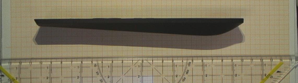
XYN815A
Dec 04, 2024BLE 5.0 Remote Control
Equipment Class
DTS - Digital Transmission System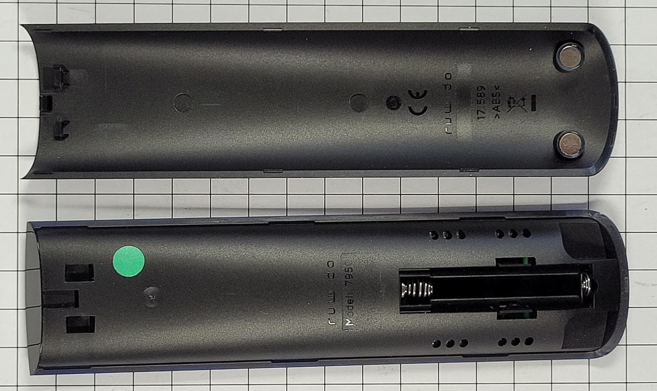
XYN795C
Aug 03, 2022Remote Control with BLE
Equipment Class
DTS - Digital Transmission System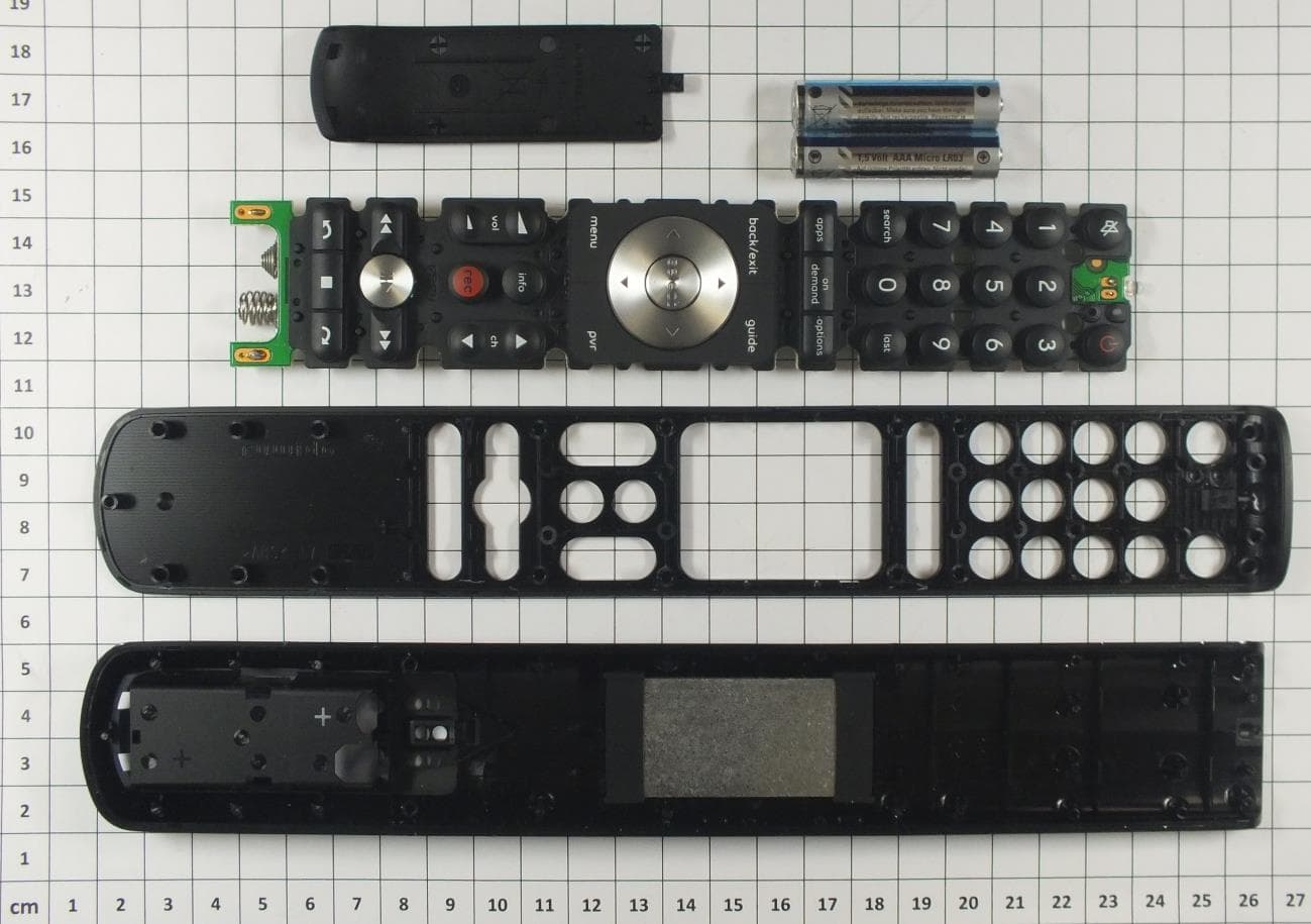
XYN761B
Jan 25, 2016Remote Control with BT 4.0 Low Energy
Equipment Class
DXX - Part 15 Low Power Communication Device Transmitter
XYN2761
Jul 29, 2013RF Remote Control
Equipment Class
DXT - Part 15 Low Power Transceiver, Rx Verified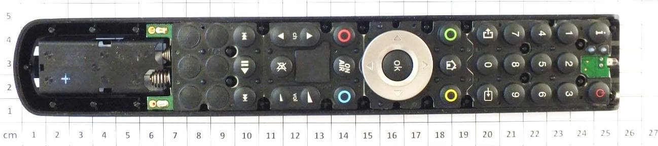
XYN2739519
Sep 25, 2012Remote Control 2.4 GHz
Equipment Class
DXX - Part 15 Low Power Communication Device Transmitter