XYN2739519Remote Control 2.4 GHz
ruwido austria GmbH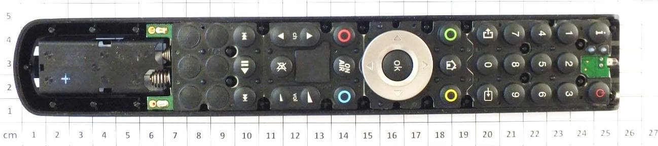
Click to zoom
Application Details
- Equipment Class
- DXX - Part 15 Low Power Communication Device Transmitter
- Date of Grant
- Sep 25, 2012
- Application Purpose
- Original Equipment
- Date of Application
- Sep 24, 2012
- Equipment Note
- Remote Control 2.4 GHz
- Frequency Range
- 2425.00000000 - 2475.00000000
- Company
- ruwido austria GmbH
- Country
- Austria
Documents & Files
Document Text
Text extracted from the exhibit documents filed with the FCC. Open a document above to read the original.
Users Manual
QUICK SETUP GUIDE Table of Contents Glossary......................................................................................................................3 Preface........................................................................................................................3 Purpose of this document....................................................................................3 Safety..................................................................................................................4 Important Safety Instructions..............................................................................5 Step 1 : Overview of the equipment...........................................................................6 Before you start...................................................................................................6 OnAir Set Back Box..............................................................................................6 OnAir Remote Control Unit..................................................................................7 Step 2 : Connecting the OnAir Set Back Box...............................................................8 Step 3 : Preparation....................................................................................................9 Preparing the television.......................................................................................9 The initial guided procedure................................................................................9 Step 4 : Pairing the Remote Control Unit..................................................................10 Step 5 : Network - which connection?.......................................................................12 Wired.................................................................................................................13 Wireless.............................................................................................................18 Step 6 : The Wi-Fi bubble..........................................................................................20 Access point Setup............................................................................................20 Advanced Features....................................................................................................22 Configuration options: Remote Control .............................................................22 Configuration options: Reboot...........................................................................22 Configuration options: System Info...................................................................22 Configuration options: Advanced.......................................................................23 Define the System Environment........................................................................27 Manual Setup - Remote Control Unit........................................................................28 RCU programming Mode....................................................................................28 Test the TV functions.........................................................................................28 Re- assigning 'Key Groups' to IR/RF...................................................................28 Useful commands for problem solving..............................................................29 Troubleshooting ........................................................................................................31 2 Glossary SBB OnAir Set Back Box RCURemote Control Unit IRInfrared: the signal used to drive most television RF4CERadio Frequency for Consumer Electronics. The radio signal used to drive the OnAir SBB HSIAHigh Speed Internet Access. The hardware and software solution used to allow guests to access the internet. VLANVirtual Lan. The method used to separate broadcast domains within the same network. SSIDService Set Identifier. An SSID is a unique ID that consists of up to 32 characters and is used for naming wireless networks. Preface Purpose of this document This document is intended for use by customers and/or network administrators as a guide for installing and configuring the OnAir SBB. The guide is targeted for use by medium/high skilled installers and/or technicians with medium networking knowledge. If you do not have sufficient knowledge to complete the tasks in this guide please contact your local vendor for support. Please read this manual carefully before operating your set and retain it for future reference. Note that specifications are subject to change without notice. 3 Safety CAUTION: DO NOT REMOVE COVER NO USER-SERVICEABLE PARTS INSIDE REFER SERVICING TO QUALIFIED SERVICE PERSONNEL. WARNING: TO PREVENT FIRE OR ELECTRIC SHOCK HAZARD, DO NOT EXPOSE THIS PRODUCT TO RAIN OR MOISTURE. WARNING: Do not install this equipment in a confined space such as a book case or similar unit. CAUTION: Do not block any ventilation openings. Install in accordance with the manufacturer’s instructions. Slots and openings in the cabinet are provided for ventilation and to ensure reliable operation of the product and to protect it from over heating. The openings shall be never be blocked. This product shall not be placed in a built- in installation such as a bookcase or rack unless proper ventilation is provided or the manufacturer’s instruction has been adhered to. CAUTION concerning the Power Cord Most appliances recommend they be placed upon a dedicated circuit; That is, a single outlet circuit which powers only that appliance and has no additional outlets or branch circuits. Check the specification page of this owner’s manual to be certain. Do not overload wall outlets. Overloaded wall outlets, loose or damaged wall outlets, extension cords, frayed power cords, or damaged or cracked wire insulation are dangerous. Any of these conditions could result in electric shock or fire. Periodically examine the cord of your appliance, and if its a…
Text truncated - open the document above for the full version.
Cover Letter(s)
Request for Confidentiality Date: 13.09.2012 Subject: Confidentiality Request for: FCC ID: XYN2739519 ______ Pursuant to FCC 47 CRF 0.457(d) and 0.459 and IC RSP-100, Section 10, the applicant requests that a part of the subject FCC application be held confidential. Type of Confidentiality Requested Exhibit Short Term Permanent Block Diagrams Short Term External Photos Short Term Permanent* 1 Internal Photos Short Term Permanent Operation Description/Theory of Operation Short Term Permanent Parts List & Placement/BOM Short Term Permanent Tune-Up Procedure Short Term Permanent Schematics Short Term Test Setup Photos Short Term Permanent* User’s Manual *Note: ______(Insert Explanation as Necessary)______ Ruwido austria gmbh has spent substantial effort in developing this product and it is one of the first of its kind in industry. Having the subject information easily available to "competition" would negate the advantage they have achieved by developing this product. Not protecting the details of the design will result in financial hardship. Permanent Confidentiality: The applicant requests the exhibits listed above as permanently confidential be permanently withheld from public review due to materials that contain trade secrets and proprietary information not customarily released to the public. Short-Term Confidentiality: The applicant requests the exhibits selected above as short term confidential be withheld from public view for a period of (0) days from the date of the Grant of Equipment Authorization and prior to marketing. This is to avoid premature release of sensitive information prior to marketing or release of the product to the public. Applicant is also aware that they are responsible to notify ACB in the event information regarding the product or the product is made available to the public. ACB will then release the documents listed above for public disclosure pursuant to FCC Public Notice DA 04-1705. NOTE for Industry Canada Applications: The applicant understands that until such time that IC distinguishes between Short Term and Permanent Confidentiality, either type of marked exhibit above will simply be marked Confidential when submitted to IC. Sincerely, By: Manager Certification Thomas Ring 1 - The asterisked items (*) require further justification before permanent confidentiality will be allowed. These also currently require review by the FCC under their Permit-But-Ask policy before the grant is issued and can delay completion of an application. Further justification should be added to the note above. One such example for a potted device would be: “The EUT is FULLY potted using a non-removable epoxy based material. Removal of potting material causes irreparable damage to internal circuitry. See photographs exhibits that outline the device before and after potting.”
External Photos
mikes-testingpartners gmbh File No. T36339-00-00HS, page 6 of 26 Ohmstrasse 2-4 94342 STRASSKIRCHEN GERMANY Tel.:+49(0)9424-94810 Fax:+49(0)9424-9481240 Rev. No. 1.2, 9.9.2010 3 E Q U I P M E N T U N D E R T E S T 3.1 Photo documentation of the EUT External view: Internal view:
ID Label/Location Info
American Certification Body Inc. 6731 Whittier Ave, Suite C110, McLean, VA 22101, USA TCB: For our records, please confirm that the device will be shipped to the user with the battery cover removed because the FCC ID appears inside that cover. Applicant: We confirm, the device will be shipped to the user with the battery cover removed and the batteries are outside the battery case.
Internal Photos
mikes-testingpartners gmbh File No. T36339-00-00HS, page 6 of 26 Ohmstrasse 2-4 94342 STRASSKIRCHEN GERMANY Tel.:+49(0)9424-94810 Fax:+49(0)9424-9481240 Rev. No. 1.2, 9.9.2010 3 E Q U I P M E N T U N D E R T E S T 3.1 Photo documentation of the EUT External view: Internal view: mikes-testingpartners gmbh File No. T36339-00-00HS, page 7 of 26 Ohmstrasse 2-4 94342 STRASSKIRCHEN GERMANY Tel.:+49(0)9424-94810 Fax:+49(0)9424-9481240 Rev. No. 1.2, 9.9.2010 RF-unit PCB-Antenna
Test Report
FCC ID: XYN 2739519 mikes-testingpartners gmbh File No. T36339-00-00HS, page 1 of 26 Ohmstrasse 2-4 94342 STRASSKIRCHEN GERMANY Tel.:+49(0)9424-94810 Fax:+49(0)9424-9481240 Rev. No. 1.2, 9.9.2010 EMI − T E S T R E P O R T - FCC Part 15.249, RSS210 - Test Report No. : T36339-00-00HS 10. September 2012 ______________________________________________________________________________________________ Date of issue Type / Model Name : 2739 Product Description : Remote Control 2.4 GHz Applicant : ruwido austria gmbh Address : Koestendorfer Str. 8 5202 NEUMARKT, AUSTRIA Manufacturer : ruwido austria gmbh Address : Koestendorfer Str. 8 5202 NEUMARKT, AUSTRIA Licence holder : ruwido austria gmbh Address : Koestendorfer Str. 8 5202 NEUMARKT, AUSTRIA Test Result according to the standards listed in clause 1 test standards: POSITIVE The test report merely corresponds to the test sample. It is not permitted to copy extracts of these test results without the written permission of the test laboratory. FCC ID: XYN 2739519 mikes-testingpartners gmbh File No. T36339-00-00HS, page 2 of 26 Ohmstrasse 2-4 94342 STRASSKIRCHEN GERMANY Tel.:+49(0)9424-94810 Fax:+49(0)9424-9481240 Rev. No. 1.2, 9.9.2010 Contents 1 T E S T S T A N D A R D S 3 2 S U M M A R Y 4 2.1 Test result summery 4 2.2 GENERAL REMARKS: 5 2.3 FINAL ASSESSMENT: 5 3 E Q U I P M E N T U N D E R T E S T 6 3.1 Photo documentation of the EUT 6 3.2 Power supply system utilised 8 3.3 Short description of the equipment under test (EUT) 8 4 T E S T E N V I R O N M E N T 10 4.1 Address of the test laboratory 10 4.2 Environmental conditions 10 4.3 Statement of the measurement uncertainty 10 4.4 Measurement protocol for FCC and IC 11 4.5 Determination of worst case measurement conditions 12 5 T E S T C O N D I T I O N S A N D R E S U L T S 13 5.1 Conducted emissions 13 5.2 Radiated emission of the fundamental wave 14 5.3 Spurious emissions radiated 16 5.4 EBW, OBW 20 5.6 Antenna application 25 6 U S E D T E S T E Q U I P M E N T A N D A C C E S S O R I E S 26 FCC ID: XYN 2739519 mikes-testingpartners gmbh File No. T36339-00-00HS, page 3 of 26 Ohmstrasse 2-4 94342 STRASSKIRCHEN GERMANY Tel.:+49(0)9424-94810 Fax:+49(0)9424-9481240 Rev. No. 1.2, 9.9.2010 1 T E S T S T A N D A R D S The tests were performed according to following standards: FCC Rules and Regulations Part 15, Subpart A - General (September, 2011) Part 15, Subpart A, Section 15.31 Measurement standards Part 15, Subpart A, Section 15.33 Frequency range of radiated measurements Part 15, Subpart A, Section 15.35 Measurement detector functions and bandwidths FCC Rules and Regulations Part 15, Subpart C - Intentional Radiators (September, 2011) Part 15, Subpart C, Section 15.203 Antenna requirement Part 15, Subpart C, Section 15.204 External radio frequency power amplifiers and antenna modifications Part 15, Subpart C, Section 15.205 Restricted bands of operation Part 15, Subpart C, Section 15.207 Conducted limits Part 15, Subpart C, Section 15.209 Radiated emission limits, general requirements Part 15, Subpart C, Section 15.249 Operation within the bands 902 - 928 MHz, 2400 - 2483.5 MHz, 5725 - 5875 MHz, and 24.0 - 24.25 GHz ANSI C63.4: 2009 Methods of Measurement of Radio-Noise Emissions from Low- Voltage Electrical and Electronic Equipment in the Range of 9 kHz to 40 GHz. ANSI C95.1:2005 IEEE Standard for Safety Levels with respect to Human Exposure to Radio Frequency Electromagnetic Fields, 3 kHz to 300 GHz CISPR 16-4-2: 2003 Uncertainty in EMC measurement CISPR 22: 2005 Information technology equipment EN 55022: 2006 FCC ID: XYN 2739519 mikes-testingpartners gmbh File No. T36339-00-00HS, page 4 of 26 Ohmstrasse 2-4 94342 STRASSKIRCHEN GERMANY Tel.:+49(0)9424-94810 Fax:+49(0)9424-9481240 Rev. No. 1.2, 9.9.2010 2 S U M M A R Y 2.1 Test result summery WPAN device using digital modulation and operates in the 2400 MHz – 2483.5 MHz band: FCC Rule Part RSS Rule Part Description Result 15.207(a) RSS Gen, 7.2.4 AC power line conducted emissions passed 15.215(c) RSS Gen, 4.6.3 -20 dBc EBW passed 15.249(a) RSS-210, A8.4(4) Field strength of fundamental passed 15.249(d) RSS-210, A8.5 Out-of-band emission, radiated passed 15.205(a) RSS-Gen, 7.2.2 Emissions in restricted bands passed 15.35(c) RSS-Gen, 4.5 Pulsed operation not applicable - RSS-Gen, 7.2.6 Transmitter frequency stability not applicable - RSS-Gen, 4.6.1 99 % Bandwidth For information The mentioned RSS Rule Parts in the above table are related to: RSS Gen, Issue 3, December 2010 RSS 210, Issue 8, December 2010 RSS 102, Issue 4, March 2010 FCC ID: XYN 2739519 mikes-testingpartners gmbh File No. T36339-00-00HS, page 5 of 26 Ohmstrasse 2-4 94342 STRASSKIRCHEN GERMANY Tel.:+49(0)9424-94810 Fax:+49(0)9424-9481240 Rev. No. 1.2, 9.9.2010 2.2 GENERAL REMARKS: The EUT uses a RF4CE chip in ZigBee technology which is designed for the frequency band from 2400 MHz to 2483.5 MHz and has an integrated printed antenna. A temporary connector can not be implemented due to the small size of the module. A suitable test fixture can also not used to convert radiated measurements to conducted measurements therefore all measurements were performed radiated. The lowest generated frequency is 32 MHz. Therefore no measurements were done below 30 MHz. 2.3 FINAL ASSESSMENT: The equipment under test fulfills the EMC requirements cited in clause 1 test standards. Date of receipt of test sample : acc. to storage records Testing commenced on : 04 September 2012 Testing concluded on : 06 September 2012 Checked by: Tested by: Thomas Weise Dipl. Ing.(FH) Laboratory Manager Hermann Smetana Dipl.-Ing.(FH) Radio Expert FCC ID: XYN 2739519 mikes-testingpartners gmbh File No. T36339-00-00HS, page 6 of 26 Ohmstrasse 2-4 94342 STRASSKIRCHEN GERMANY Tel.:+49(0)9424-94810 Fax:+49(0)9424-9481240 Rev. No. 1.2, 9.9.2010 3 E Q U I P M E N T U N D E R T E S T 3.1 Photo documentation of the EUT External view: Internal view: FCC ID: XYN 2739519 mikes-testingpartners…
Text truncated - open the document above for the full version.
Test Setup Photos
mikes-testingpartners gmbh File No. T36339-00-00HS, page 14 of 26 Ohmstrasse 2-4 94342 STRASSKIRCHEN GERMANY Tel.:+49(0)9424-94810 Fax:+49(0)9424-9481240 Rev. No. 1.2, 9.9.2010 5.2 Radiated emission of the fundamental wave For test instruments and accessories used see section 6 Part CPR 3. 5.2.1 Description of the test location Test location: Anechoic chamber 2 Test distance: 3 m 5.2.2 Photo documentation of the test set-up mikes-testingpartners gmbh File No. T36339-00-00HS, page 16 of 26 Ohmstrasse 2-4 94342 STRASSKIRCHEN GERMANY Tel.:+49(0)9424-94810 Fax:+49(0)9424-9481240 Rev. No. 1.2, 9.9.2010 5.3 Spurious emissions radiated For test instruments and accessories used see section 6 Part SER 2, SER 3. 5.3.1 Description of the test location Test location: OATS 1 Test location: Anechoic chamber 2 Test distance: 3 m 5.3.2 Photo documentation of the test set-up mikes-testingpartners gmbh File No. T36339-00-00HS, page 17 of 26 Ohmstrasse 2-4 94342 STRASSKIRCHEN GERMANY Tel.:+49(0)9424-94810 Fax:+49(0)9424-9481240 Rev. No. 1.2, 9.9.2010 5.3.3 Applicable standard According to FCC Part 15C, Section 15.249 (d): Emission radiated outside of the specified frequency bands, except harmonics, shall be attenuated by at least 50 dB below the level of the fundamental or to the general radiated limit in FCC Part 15C, Section 15.209, whichever is the lesser attenuation. 5.3.4 Description of Measurement The radiated emissions from the EUT are measured in the frequency range of 9 kHz to 1000 MHz using a tuned receiver and appropriate broadband linearly polarized antennas. The set up of the EUT will be in accordance to ANSI C63.4. In the frequency range above 1 GHz a spectrum analyser is used with appropriate linear polarized antennas. If the emission level in peak mode complies with the average limit then testing will be stopped and peak values of the EUT will be reported, otherwise, the emission will be measured in average mode again and reported. During the test, the EUT was set into continuous transmitting mode modulated. Instrument settings: 9 kHz – 150 kHz RBW: 200 Hz 150 kHz - 30 MHz RBW: 9 kHz 30 MHz – 1000 MHz: RBW: 120 kHz 1000 MHz – 40 GHz RBW: 1 MHz 5.3.5 Test result f < 1 GHz: No emission could be detected within 20 dB to the limit. f > 1 GHz: No emission could be detected within 20 dB to the limit. Note: Emissions smaller than 20 dB to the limit needs not to be reported. mikes-testingpartners gmbh File No. T36339-00-00HS, page 20 of 26 Ohmstrasse 2-4 94342 STRASSKIRCHEN GERMANY Tel.:+49(0)9424-94810 Fax:+49(0)9424-9481240 Rev. No. 1.2, 9.9.2010 5.4 EBW, OBW For test instruments and accessories used see section 6 Part MB. 5.4.1 Description of the test location Test location: Anechoic chamber 2 5.4.2 Photo documentation of the test set-up 5.4.3 Applicable standard According to FCC Part 15, Section 15.215(c): Intentional radiators operating under the alternative provisions to the general emission limits, as contained in Section 15.217 through Section 15.257, must be designed to ensure that the 20 dB bandwidth of the emission is contained within the frequency band designated in the rule section under which the equipment is operated. 5.4.4 Description of Measurement The bandwidth is measured at an amplitude level reduced from the reference level by a specified ratio of -20 dB. The reference level is the level of the highest signal amplitude observed from the transmitter at the fundamental frequency. Alternative is the x-dB-down function of the analyser used. The EBW is than directly shown in the marker display. The measurement is performed with normal modulation and a transfer rate means the worst case. Spectrum analyser settings: RBW: 100 kHz VBW: 300 kHz Span: 10 MHz Detector: Max peak
Contact Information
Applicant
Rafael Jaburek(Project Manager)
Technical Contact
Test Firm
CSA Group Bayern GmbHThomas Weise
Technical Specifications
| # | Rule Parts | Frequency Range | Power Output |
|---|---|---|---|
| 1 | 15C | 2.42 GHz - 2.48 GHz | - |
Other Applications from ruwido austria GmbH
XYN815A
Dec 04, 2024BLE 5.0 Remote Control
Equipment Class
DTS - Digital Transmission System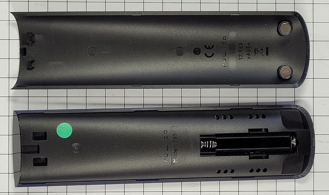
XYN795C
Aug 03, 2022Remote Control with BLE
Equipment Class
DTS - Digital Transmission System
XYN761B
Jan 25, 2016Remote Control with BT 4.0 Low Energy
Equipment Class
DXX - Part 15 Low Power Communication Device Transmitter
XYN2761
Jul 29, 2013RF Remote Control
Equipment Class
DXT - Part 15 Low Power Transceiver, Rx Verified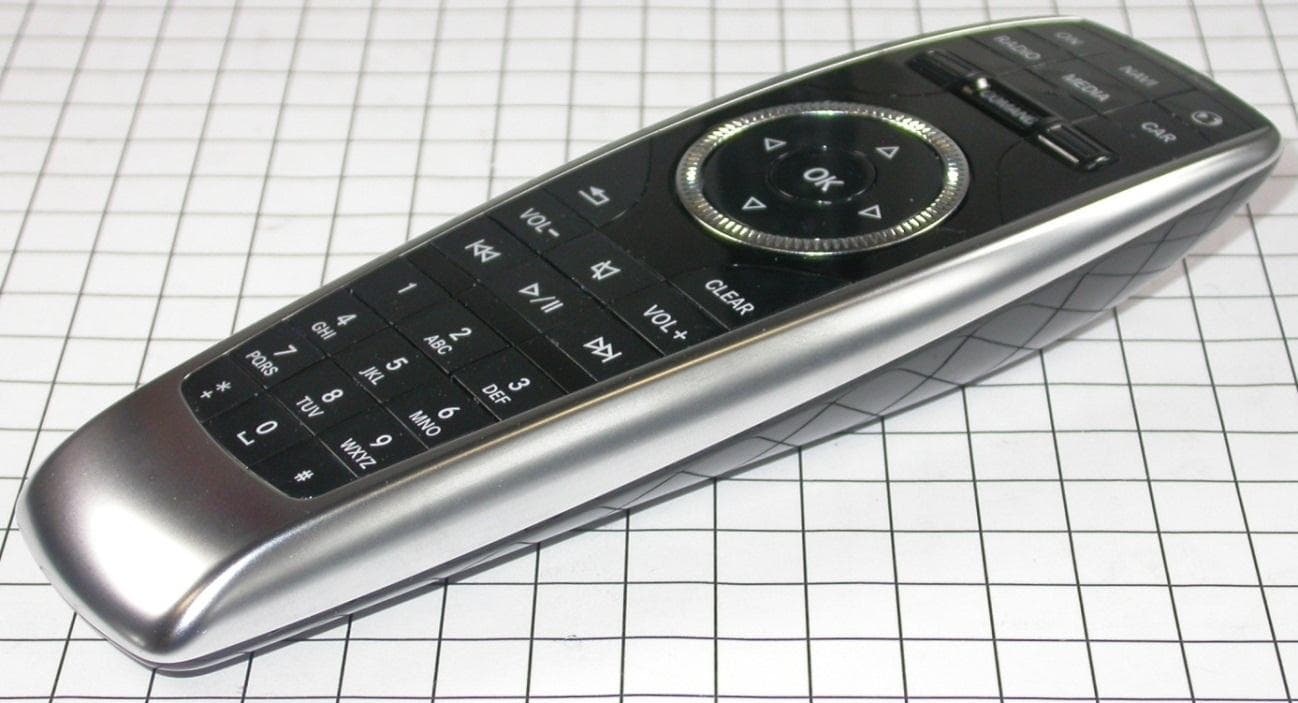
XYN2738
Dec 20, 2012Remote Control 2.4 GHz
Equipment Class
DXX - Part 15 Low Power Communication Device Transmitter