Y7HXGCS85RFID Reader
Schneider Electric Industries France L'Isle d'Espagnac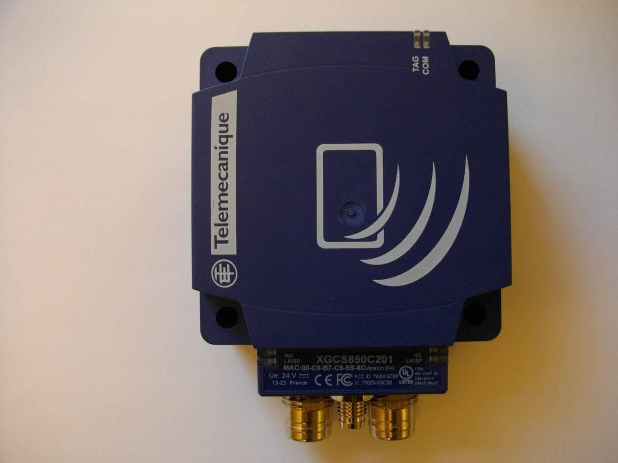
Click to zoom
Application Details
- Equipment Class
- DXX - Part 15 Low Power Communication Device Transmitter
- Date of Grant
- Sep 05, 2013
- Application Purpose
- Original Equipment
- Date of Application
- Sep 05, 2013
- Equipment Note
- RFID Reader
- Frequency Range
- 13.56000000 - 13.56000000
- Country
- France
Documents & Files
Document Text
Text extracted from the exhibit documents filed with the FCC. Open a document above to read the original.
Users Manual
WARNING / AVERTISSEMENT / ADVERTENCIA en fr es © 2013 Schneider Electric. “All Rights Reserved.” Electrical equipment should be installed, operated and maintained only by qualified personnel. No responsibility is assumed by Schneider Electric for any consequences arising out of the use of this material. Les équipements électriques doivent être installés, exploités et entretenus par un personnel qualifié. Schneider Electric décline toute responsabilité quant aux conséquences de l’utilisation de ce matériel. Sólo el personal de servicio cualificado podrá instalar, utilizar, reparar y mantener el equipo eléctrico. Schneider Electric no asume las responsabilidades que pudieran surgir como consecuencia de la utilización de este material. Diagnostic LEDs / Voyants de diagnostic / LED de diagnóstico UNINTENDED EQUIPMENT OPERATION p Turn off power supplying the Smart Antenna p This Class B product may cause radio interference. p The cable routing rules listed in the User Guide of the EtherNet/IP splitter box must be followed. p Properly fit all connectors with cables or sealing plugs and tighten. p D o not use factory configured IP address for operation. p Do not exceed the maximum number of word to read or write. p Consult the User Guide of the EtherNet/IP Smart Antenna for more detailed informations. Failure to follow these instructions can result in death, serious injury, or equipment damage. FONCTIONNEMENT IMPREVU DE L'EQUIPEMENT p Couper l'alimentation de la Smart Antenna p Ce produit de classe B peut générer des interférences radio. p Il faut respecter les consignes de cheminement du câble indiquées dans le manuel utilisateur du répartiteur EtherNet/IP. p Équiper correctement tous les connecteurs de câbles ou de bouchons d'étanchéité et les serrer. p Ne pas utiliser l'adresse IP configurée en usine lors du fonctionnement. p Ne pas dépasser la nombre maximum de mots à lire ou écrire. p Consulter le manuel utilisateur de la Smart Antenna EtherNet/IP pour plus de renseignements. Le non-respect de ces instructions peut provoquer la mort, des blessures graves ou des dommages matériels. FUNCIONAMIENTO INESPERADO DEL EQUIPO p Desconecte la alimentación eléctrica de la Smart Antenna. p Este producto de clase B puede causar interferencias de radio. p Se deben seguir las reglas de cableado enumeradas en la guía de usuario de la caja de distribución EtherNet/IP. p Ajuste correctamente todos los conectores con los cables o tapones de cierre y apriételos. p No utilice la dirección IP configurada en fábrica para el funcionamiento. p No supere el número máximo de palabras de lectura o escritura. p Consulte la guía del usuario de la Smart Antenna EtherNet/IP para obtener más información. Si no se siguen estas instrucciones pueden producirse lesiones personales graves o mortales o daños en el equipo. www.tesensors.com XGCS850C201 4/4 HRBxxxxx 00 03 - 2013 en fr es Note: The user guide (N° EIO0000001601) and EDS file are stored in the internal memory and are accessible from the Web server of the XGCS850C201 Smart Antenna (page “Documentation”). These documents are also accessible on Web site “www.tesensors.com”. Note : le manuel utilisateur (n° EIO0000001602) et le fichier EDS sont stockés dans la mémoire interne et sont accessibles à partir du serveur Web de la Smart Antenna XGCS850C201 (page “Documentation”). Ces documents se trouvent également sur le site Web “www.tesensors.com”. Nota: La guía del usuario (N°EIO0000001603) y el archivo EDS están almacenados en la memoria interna y sepuede acceder a ellos desde el servidor Web de la Samart Antenna XGCS850C201 (página “Documentation” (Documentación)). También se puede acceder aestos documentos en el sitio web “www.tesensors.com”. en fr es en fr es 7 5 6 9 3 2 4 1 8 6 7 5 www.tesensors.com XGCS850C201 1/4 03 - 2013 Printed in HRBxxxxx 00 Description / Description / Descripción EtherNet/IP Smart Antenna EtherNet/IP Smart Antenna EtherNet/IP Smart Antenna en fr es TAG : Tag LED M12 socket Ethernet port Nr 1 1 2 3 4 5 6 7 8 9 COM : Communication LED M8 Socket Power supply 24V NS : NetworkStatusLED LK/SP : Ethernet communication port Nr.1 LED M12 socket Ethernet port Nr 2 LK/SP : Ethernet communcation port Nr.2 LED MS : Ethernet Module Status LED Setting TAG : Tag LED M12 socket Ethernet port Nr 1 COM : Communication LED M8 Socket Power supply 24V NS : NetworkStatusLED LK/SP : Ethernet communication port Nr.1 LED M12 socket Ethernet port Nr 2 LK/SP : Ethernet communcation port Nr.2 LED MS : Ethernet Module Status LED Setting TAG : Tag LED M12 socket Ethernet port Nr 1 COM : Communication LED M8 Socket Power supply 24V NS : NetworkStatusLED LK/SP : Ethernet communication port Nr.1 LED M12 socket Ethernet port Nr 2 LK/SP : Ethernet communcation port Nr.2 LED MS : Ethernet Module Status LED Setting 1 2 3 48 9 LED Name LED stateDescriptionSmart antenna state Solid GreenTag presenceA tag is detected – dialog ok 1 flashNo tag detectedWaiting for a tag Red flashesRFID errorsErrors detected in the dialog with the tag Green flashes Requests received from a client OK Red flashesErrors in requests received from a client Error code returned to the client (no tag / bad parameters,..) Solid GreenThe network is operating normally OK 4 flashes A duplicate IP condition exists The smart antenna operates offline 5 flashesThe smart antenna attempts to get an IP configuration from BootP server The smart antenna sends BOOTP/DHCP requests to a BootP server and awaits a reply 6 flashesOperations are normal with default IP adressing settings BootP requests timed out. The Smart antenna applied the default Ip address (192.168.0.10) 7 flashesOperations are in kernel m ode The smart antenna attempts to acquire a new firmware. Solid GreenEthernet link present at 100 Mbps OK Flashing Green Traffic at 100 MbpsOK Solid Yellow Ethernet link present at 10 Mbps OK Flashing Yellow Traffic at 10 MbpsOK OKOn OffNo power supply Not ready 4 8 9 Link Activity (port 1 & 2) MS (Ethernet module) Green 1 2…
Text truncated - open the document above for the full version.
Users Manual
EIO0000001601.00 www.schneider-electric.com DI[D-SE-0029826.1.6] RFID OsiSense® XG EIO0000001601 Draft 2013/07/17 RFID OsiSense® XG RFID OsiSense ® XG EtherNet/IP Smart Antenna User Manual Draft 2013/07/17 DI[D-SE-0029826.1.6] 2EI O0000001601 Draft 2013/07/17 The information provided in this documentation contains general descriptions and/or technical characteristics of the performance of the products contained herein. This documentation is not intended as a substitute for and is not to be used for determining suitability or reliability of these products for specific user applications. It is the duty of any such user or integrator to perform the appropriate and complete risk analysis, evaluation and testing of the products with respect to the relevant specific application or use thereof. Neither Schneider Electric nor any of its affiliates or subsidiaries shall be responsible or liable for misuse of the information contained herein. If you have any suggestions for improvements or amendments or have found errors in this publication, please notify us. No part of this document may be reproduced in any form or by any means, electronic or mechanical, including photocopying, without express written permission of Schneider Electric. All pertinent state, regional, and local safety regulations must be observed when installing and using this product. For reasons of safety and to help ensure compliance with documented system data, only the manufacturer should perform repairs to components. When devices are used for applications with technical safety requirements, the relevant instructions must be followed. Failure to use Schneider Electric software or approved software with our hardware products may result in injury, harm, or improper operating results. Failure to observe this information can result in injury or equipment damage. © 2013 Schneider Electric. All rights reserved. EIO0000001601 Draft 2013/07/173 DI[D-SE-0029826.1.6] Table of Contents Safety Information . . . . . . . . . . . . . . . . . . . . . . . . . . . . .5 About the Book. . . . . . . . . . . . . . . . . . . . . . . . . . . . . . . .7 Chapter 1 General Information . . . . . . . . . . . . . . . . . . . . . . . . . . . .9 System Presentation . . . . . . . . . . . . . . . . . . . . . . . . . . . . . . . . . . . . . . 10 Exchange Principle . . . . . . . . . . . . . . . . . . . . . . . . . . . . . . . . . . . . . . . 12 Overview of the OsiSense XG Range . . . . . . . . . . . . . . . . . . . . . . . . . 14 System View . . . . . . . . . . . . . . . . . . . . . . . . . . . . . . . . . . . . . . . . . . . . 15 Chapter 2 Specifications and Physical Description . . . . . . . . . . .19 Smart Antenna Characteristics . . . . . . . . . . . . . . . . . . . . . . . . . . . . . . 20 Tags Characteristics . . . . . . . . . . . . . . . . . . . . . . . . . . . . . . . . . . . . . . 23 Description of the Smart Antenna . . . . . . . . . . . . . . . . . . . . . . . . . . . . 27 Connecting the OsiSense XG Smart Antenna. . . . . . . . . . . . . . . . . . . 29 Wiring Accessories . . . . . . . . . . . . . . . . . . . . . . . . . . . . . . . . . . . . . . . 30 Smart Antennas Wiring Example. . . . . . . . . . . . . . . . . . . . . . . . . . . . . 32 Chapter 3 Installing the System . . . . . . . . . . . . . . . . . . . . . . . . . . .33 Installation Precautions . . . . . . . . . . . . . . . . . . . . . . . . . . . . . . . . . . . . 34 IP Address Configuration. . . . . . . . . . . . . . . . . . . . . . . . . . . . . . . . . . . 40 Chapter 4 Operating Principles . . . . . . . . . . . . . . . . . . . . . . . . . . .43 Read/Write Operating Mode . . . . . . . . . . . . . . . . . . . . . . . . . . . . . . . . 44 Memory Zones. . . . . . . . . . . . . . . . . . . . . . . . . . . . . . . . . . . . . . . . . . . 48 Smart Antenna System Memory Zone . . . . . . . . . . . . . . . . . . . . . . . . 49 Smart Antenna Command/Instructions Memory Zone . . . . . . . . . . . . 51 Chapter 5 EtherNet/IP Communications Support . . . . . . . . . . . . .61 5.1 Object Model . . . . . . . . . . . . . . . . . . . . . . . . . . . . . . . . . . . . . . . . . . . . 62 About the Object Model . . . . . . . . . . . . . . . . . . . . . . . . . . . . . . . . . . . . 63 Assembly Object (Class ID 4) . . . . . . . . . . . . . . . . . . . . . . . . . . . . . . . 65 Modbus Object (Class ID 0x44). . . . . . . . . . . . . . . . . . . . . . . . . . . . . . 67 5.2 Unity Pro: EtherNet/IP Application Example . . . . . . . . . . . . . . . . . . . . 69 Presentation . . . . . . . . . . . . . . . . . . . . . . . . . . . . . . . . . . . . . . . . . . . . 70 Creating a Project . . . . . . . . . . . . . . . . . . . . . . . . . . . . . . . . . . . . . . . . 71 Configuring the TSXETC101 EtherNet/IP Communication Module. . . 72 Configuring the Ethernet Smart Antenna. . . . . . . . . . . . . . . . . . . . . . . 75 Read Application Example . . . . . . . . . . . . . . . . . . . . . . . . . . . . . . . . . 80 DI[D-SE-0029826.1.6] 4EI O0000001601 Draft 2013/07/17 5.3 RSLogix: EtherNet/IP Application Example . . . . . . . . . . . . . . . . . . . . . 82 Configuring a Smart Antenna on an EtherNet/IP Network with a ControlLogix PLC . . . . . . . . . . . . . . . . . . . . . . . . . . . . . . . . . . . . . . . . . 83 Read the Assembly 102 (General Status) or 103 (Read Table) Using an Explicit Message . . . . . . . . . . . . . . . . . . . . . . . . . . . . . . . . . . . . . . . 90 Reading/Writing Request with the Modbus Object. . . . . . . . . . . . . . . . 94 Chapter 6 Modbus TCP/IP Communications Support . . . . . . . . .101 Modbus Commands Supported by the Smart Antenna . . . . . . . . . . . . 102 Modbus Requests Description . . . . . . . . . . . . . . . . . . . . . . . . . . . . . . . 107 Modbus Application Example. . . . . . . . . . . . . . . . . . . . . . . . . . . . . . . . 111 Chapter 7 Web Server . . . . . . . . . . . . . . . . . . . . . . . . . . . . . . . . . . .115 Web Server Access . . . . . . . . . . . . . . . . . . .…
Text truncated - open the document above for the full version.
Cover Letter(s)
Schneider Electric Industries SAS Zone Industrielle n° 3 BP 660 16340 L’ISLE D’ESPAGNAC, FRANCE To: Federal Communications Commission 7435 Oakland Mills Road Columbia, MD 21046-1609 Curtis-Straus LLC TCB One Distribution Center Circle, #1 Littleton, MA 02702 Re: Confidentiality Request Gentlemen: This letter is to comply with 47 CFR 0.457(d)(2) pertaining to confidential material. “Schneider Electric Industries France L'Isle d'Espagnac” requests that the following documents regarding this submission for FCC ID Y7HXGCS85 be kept confidential: 1. Schematics 2. Block Diagrams 3. Circuit/Technical Description The material above contains technical data, which would customarily be guarded from competitors. Sincerely, Jean-Pierre Laidet Product Certification Manager July 5, 2013
External Photos
External view FCC ID: Y7HXGCS85 IC: 7002C-XGCS85
ID Label/Location Info
Number:Revision:Sheet: State: All information and data contained in this document are the exclusive property of Schneider Electric Industries SAS and may neither be used nor disclosed without its prior written consent Scale: Tolerancing standard: Units of measure: 1/1 ETIQUETTE PRODUIT TIPI TIPI PRODUCT LABEL HRB57225030 1 3.00 scale 1 XGCS850C201 IND. CONT. EQ. 170M MAC:00.00.00.00.00.00 Ue: 24 V LK/SP LK/SP MS NS Use only in class2 circuit FCC ID: Y7HXGCS85 IC: 7002C-XGCS85 Version xxxx YY-WW France Date code : YY-WW Arial font size:1,4mm YY : 2 last digits of the year of the product manufacture WW : Week number of the poduct manufacture Scale 3 All texts and logos printed in black XGCS850C201 IND. CONT. EQ. 170M MAC:00.00.00.00.00.00 Ue: 24 V LK/SPLK/SP MS NS Use only in class2 circuit FCC ID: Y7HXGCS85 IC: 7002C-XGCS85 Version xxxx YY-WW France
Internal Photos
Internal view FCC ID: Y7HXGCS85 IC: 7002C-XGCS85 The Osisense XG Smart antenna is structured as below : Mother board Etherkit Antenna board Ferrite + copper shield Plastic enclosure Reader board Supply connector (M8) Ethernet connectors (M12) Light guides 1 Mother board : Top side : Bottom side : 4. 2 Etherkit : Top side : Bottom side : 3 Reader board : Top side : Bottom side : 4 Antenna board : Coil side : Components side :
Test Report
Accréditation N° 1-0312 Scope available on www.cofrac.fr This document shall not be reproduced, except in full, without the written approval of the LCIE. This document contains results related only to the item tested. It does not imply the conformity of the whole production to the items tested. Unless otherwise specified, the decision of conformity takes into account the uncertainly of measures. This document doesn’t anticipate any certification decision. The COFRAC accreditation only attests the technical capability of the testing laboratory for the tests covered by the accreditation. Only tests not covered by the COFRAC accreditation are marked with asterisk (*). TEST REPORT N°121425-642650A FCC REGISTRASTION NUMBER 888863 Industry Canada number 6230B-1 ISSUED TO : SCHNEIDER ELECTRIC BP 660 ZI N°3 16340 L’Isle d’Espagnac – France SUBJECT : ELECTROMAGNETIC COMPATIBILITY TESTS ACCORDING TO THE STANDARD 47 CFR PART 15, SUBPART C, 15.225 and RSS-GEN, RSS-102, RSS-210 Apparatus under test Product : ETHERNET / IP SMART ANTENNA Trade mark : Telemecanique Sensors Manufacturer : Schneider Electric Model : - Reference : XGCS850C201 Serial number : - Applicant : SCHNEIDER ELECTRIC FCC ID : Y7HXGCS85 IC : 7002C-XGCS85 Test date : 2013-06-20 & 2013-08-30 & 2013-09-02 Composition of document : 26 pages Fontenay-Aux-Roses, September 03 nd , 2013 Written by The technical manager, Stéphane PHOUDIAH & Laurent DENEUX Patrick TEIXEIRA TEST REPORT N° 121425-642650A Page 2 FCC ID: Y7HXGCS85 IC: 7002C-XGCS85 TABLE OF CONTENTS 1 – GENERAL 1.1 – Summary of test results Page 3 1.2 – References Page 3 1.3 – Equipment under test specification Page 5 2 – TEST RESULTS 2.1 – Power line conducted emission test Page 8 2.2 – Field strength within the 13.110-14.010MHz band Page 12 2.3 – Field strength outside the 13.110-14.010MHz band Page 16 2.4 – Frequency tolerance over extreme voltage and temperature condition Page 23 TEST REPORT N° 121425-642650A Page 3 FCC ID: Y7HXGCS85 IC: 7002C-XGCS85 1 – GENERAL 1.1 – Summary of test results Radiated emissions are made in open field site located Chemin des Hautes Peines at ECUELLES (77260, FRANCE). FCC REGISTRASTION NUMBER 888863 Industry Canada number 6230B-1 A description of the test facility is on file with the FCC. 47 CFR Part 15 & RSS 210 Paragraph No. Name of test Remarks Result § 15.203 Antenna requirement Internal antenna Pass § 15.205 Restricted band operation Pass § 15.207 (a) & RSS GEN §7.2.2 Power line conducted limits Pass § 15.209 (a) (b) (c) (d) & table 3 RSS 210 Radiated measurement of spurious emissions Pass §15.225 (a) (b) (c) & RSS 210 Field strength within the band 13.110-14.010 MHz Pass §15.225 (d) & A2.6 of RSS 210 Field strength outside of the bands 13.110-14.010 MHz Pass §15.225 (e) & A.2 of RSS 210 Frequency stability over extreme temperature and voltage conditions Pass NA : Not Applicable Remark: 1.2 – References Measurements were performed in accordance with the following standards: 47 CFR Part 15 of October, 2012: Code of federal regulations – Telecommunication –Radiofrequency devices RSS-Gen of December 2010: General Requirements and Information for the Certification of Radiocommunication Equipment RSS-102 of Mars 2010: Radio Frequency Exposure Compliance of Radiocommunication Apparatus RSS-210 of December 2010: Low-power Licence-exempt Radiocommunication Devices (All Frequency Bands): Category I Equipment ANSI C63.4 of December 11, 2003: American national standard for methods of measurement of radio noise emissions from low-voltage electrical and electronic equipment in the range of 9 kHz to 40 GHz. CISPR 16-4-2 of November, 2003: International electrotechnical commission - Specification for radio disturbance and immunity measuring apparatus and methods – Uncertainties, statistics and limit modelling – Uncertainty in EMC measurements. TEST REPORT N° 121425-642650A Page 4 FCC ID: Y7HXGCS85 IC: 7002C-XGCS85 1.3 – test methodology Radio performance tests procedures given in part 15: Paragraph 33: frequency range of radiated measurements Paragraph 35: measurement detector functions and bandwidths Paragraph 203: antenna requirement Paragraph 205: restricted bands of operation Paragraph 207: conducted limits Paragraph 209: radiated emission limits; general requirements Paragraph 225: radiated emission limits; general requirements TEST REPORT N° 121425-642650A Page 5 FCC ID: Y7HXGCS85 IC: 7002C-XGCS85 1.3 - Equipment under test specification 1.3.1 – General equipment information Applicant : SCHNEIDER ELECTRIC BP 660 ZI N°3 16340 L’Isle d’Espagnac – France Manufacturer : SCHNEIDER ELECTRIC BP 660 ZI N°3 16340 L’Isle d’Espagnac – France Dimensions : 108 x 80 x 40 mm Frequency band : 13.56 MHz Number of channel : 1 Channel spacing : - User frequency adjustment : No User power adjustment : No Type of antenna : Dedicated loop antenna permanently connected on the PCB Is the operation point to point? : No Power supply : 24 V-dc Internal frequencies : Ethernet 25MHz, Switching power supply oscillator (3.3 V) 260KHz, Switching power supply oscillator (2.5 V & 1 V) 1.6MHz, Asic clock oscillator 25MHz, Mico-controller clock 40MHz-crystal, RFID-controller clock 13.56MHz-crystal. External links Marking plate : Port 1 : M8 socket power supply 24 V-dc Port 2 : M12 socket Ethernet port Nr1 Port 3 : M12 socket Ethernet port Nr2 TEST REPORT N° 121425-642650A Page 6 FCC ID: Y7HXGCS85 IC: 7002C-XGCS85 1.3.2 – Description of modifications -Adding a ferrite reference 74271221 on 24 V-dc power cable -Adding a ferrite reference 74271131 on Ethernet Cable 1.3.3 – Description of operation The equipment was configured in the following operation mode: - Maximum transmission power: Permanently emission at 13.56 MHz with the usual modulation. TEST REPORT N° 121425-642650A Page 7 FCC ID: Y7HXGCS85 IC: 7002C-XGCS85 1.3.4 – Photographs of the sample General view of OsiSence XG Range The Tag OsiSence XG Range marking plate TEST REPORT N° 121425-642650A Page 8 FCC ID: Y7HXGCS85 IC: 7002C-X…
Text truncated - open the document above for the full version.
Test Setup Photos
Test setup photos FCC ID: Y7HXGCS85 IC: 7002C-XGCS85 Test setup for power line conducted emissions Test setup for radiated field strength Test setup for radiated field strength Test setup for radiated field strength Test setup for frequency stability measurement in extreme conditions
Contact Information
Applicant
Jean-Pierre LAIDET(Product Certification Manager)
Test Firm
LCIE Sud-EstJacques Lorquin
Technical Specifications
| # | Rule Parts | Frequency Range | Power Output |
|---|---|---|---|
| 1 | 15C | 13.56 MHz - 13.56 MHz | - |
Other Applications from Schneider Electric Industries France L'Isle d'Espagnac
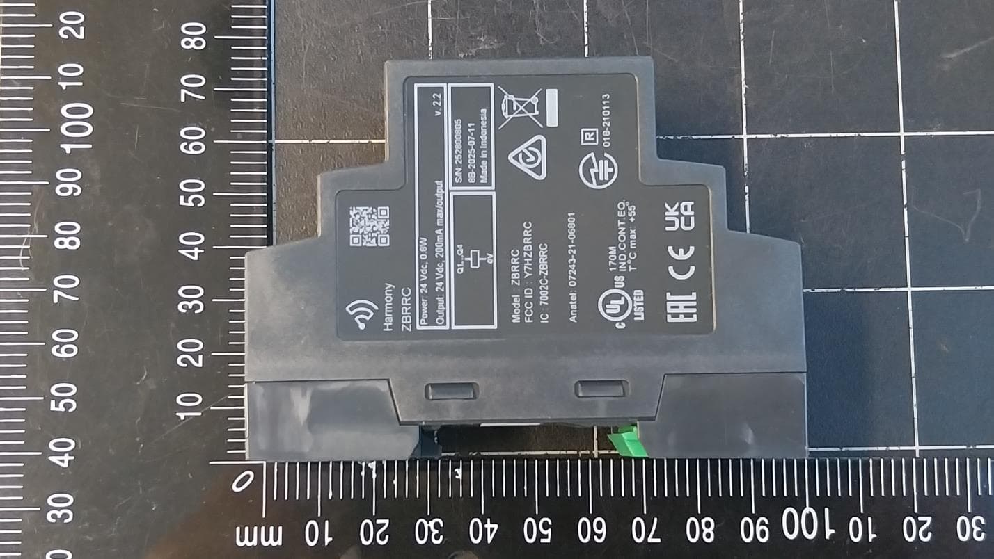
Y7HZBRRC
May 06, 2026Programmable receiver, Harmony XB5R, 4 PNP, 2 buttons, 6 indicating LEDs, monostable, 24VDC
Equipment Class
DTS - Digital Transmission System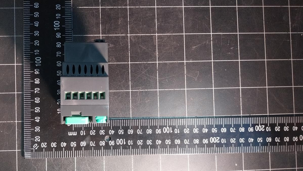
Y7HZBRRA
May 01, 2026Configurable receiver, Harmony XB5R, 2 relays, 2 buttons, 6 indicating LEDs, monostable, bistable, stop start, 24...240V AC/DC
Equipment Class
DTS - Digital Transmission System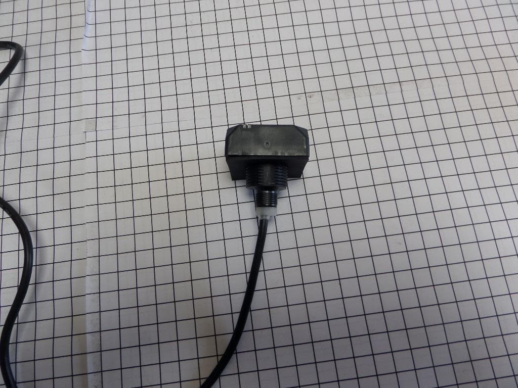
Y7HZB5SK
Jun 29, 2021Ositrack RFID compact stations (ref ZB5SKR0...) is a range of short range devices with integrated antenna, operating with a carrier frequency of 13.56 MHz and designed for mounting through a 022 hole.
Equipment Class
DXX - Part 15 Low Power Communication Device Transmitter
Y7HZART
Apr 29, 2014ZART REMOTE use a Bluetooth module
Equipment Class
DTS - Digital Transmission System
Y7HZARB
Apr 27, 2014ZARB BASE use a Bluetooth module
Equipment Class
DTS - Digital Transmission System