YAIWB15Wireless Audio Module
InnoComm Mobile Technology Corporation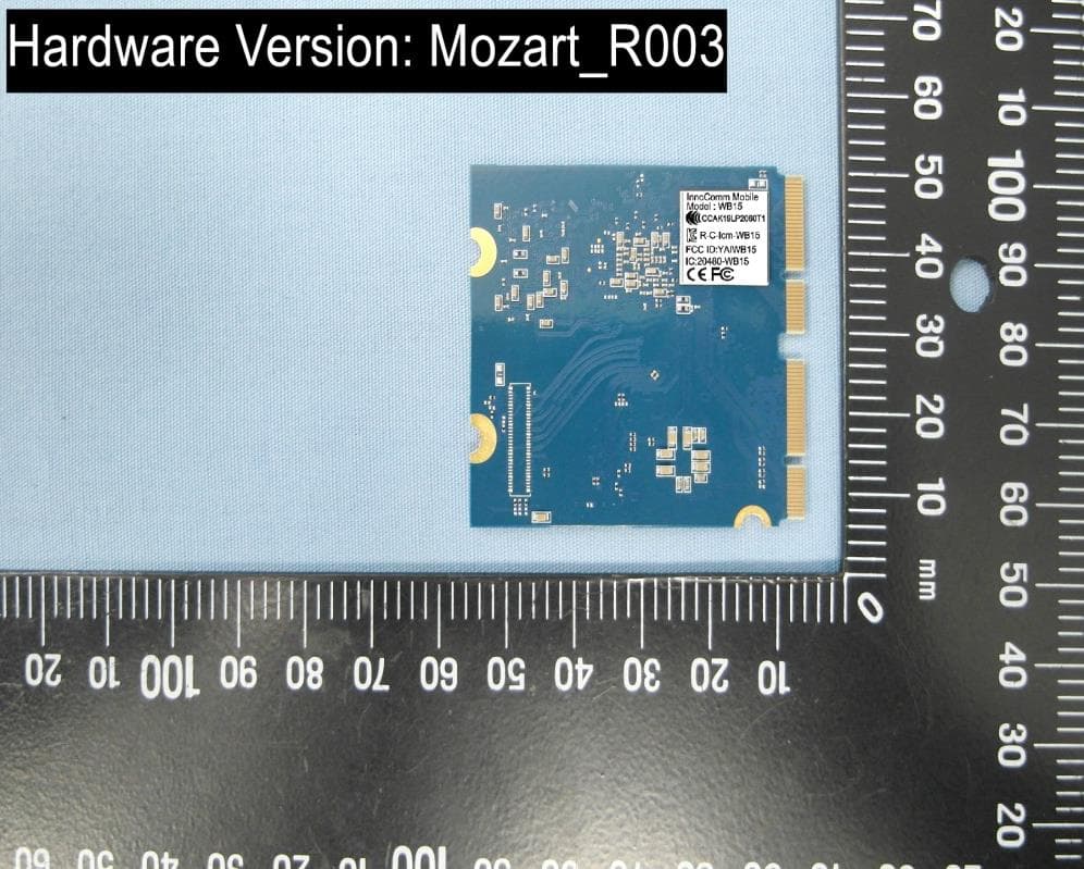
Click to zoom
Application Details
- Equipment Class
- NII - Unlicensed National Information Infrastructure TX
- Date of Grant
- Nov 14, 2020
- Application Purpose
- Original Equipment
- Date of Application
- Nov 12, 2020
- Equipment Note
- Wireless Audio Module
- Frequency Range
- 5745.00000000 - 5825.00000000
- Country
- Taiwan
Documents & Files
Document Text
Text extracted from the exhibit documents filed with the FCC. Open a document above to read the original.
Users Manual
www.innocomm.comii WB15 User Guide Copyright and third-party information as required www.innocomm.comiii Revisions History Date Version Number Document Changes 2019/02/15 0.0 Initial Draft 2019/04/02 1.0 Official release 2019/08/02 1.1 Add Disclaimer; Add Chapter1.5 2019/08/21 1.2 Update Diagram 2019/10/17 1.3 Remove Optional I/O J103 Disclaimer WB15 SOM are supplied “as is” and without warranties of any kind, express, implied, or statutory including, but not limited to, any implied warranty for a particular purpose. No license is granted by implication or otherwise under any patents or other intellectual property by application or use of evaluation boards. Information furnished by InnoComm is believed to be accurate and reliable. InnoComm reserves the right to change specifications or product description in this document at any time without notice. Should Buyer purchase or use InnoComm’s products for any such unintended or unauthorized application, Buyer shall indemnify and hold InnoComm harmless against all claims and damages. InnoComm is the trademarks of InnoComm Mobile Technology Corp.Other trademarks and registered trademarks mentioned herein are the property of their respective owners. www.innocomm.comiv Table of Contents 1 Overview ................................................................................................................................................................................. 5 1.1 ... General Information ......................................................................................................................................................... 5 1.2 ... Architecture and Block Diagram ................................................................................................................................ 6 1.3 ... Feature Summary .............................................................................................................................................................. 6 1.4 ... Dimension .............................................................................................................................................................................. 7 1.5 ... Electrical Specification .................................................................................................................................................... 8 2 Main Hardware Components ......................................................................................................................................... 8 2.1 ... CPU ......................................................................................................................................................................................... 10 2.2 ... Memory ................................................................................................................................................................................ 10 2.3 ... Power Management IC ................................................................................................................................................. 10 2.4 ... eMMC Storage ................................................................................................................................................................... 11 2.5 ... Wi-Fi/Bluetooth Module .............................................................................................................................................. 11 3 WB15 iMX8M Mini Interfaces and Connectors .................................................................................................... 12 3.1 ... J101 Connector ................................................................................................................................................................. 12 3.2 ... J102 Connector ................................................................................................................................................................. 13 3.3 ... Power Signals .................................................................................................................................................................... 15 3.4 ... Ethernet ............................................................................................................................................................................... 15 3.5 ... USB ......................................................................................................................................................................................... 15 3.6 ... UARTs ................................................................................................................................................................................... 16 3.7 ... I2Cs......................................................................................................................................................................................... 16 3.8 ... eCSPI...................................................................................................................................................................................... 17 3.9 ... DSI Interface ...................................................................................................................................................................... 17 3.10 . SD/MMC ............................................................................................................................................................................... 18 3.11 . SAIs......................................................................................................................................................................................... 18 3.12 . SPDIF ..................................................................................................................................................................................... 20 4 User interface Getting start ...............…
Text truncated - open the document above for the full version.
Cover Letter(s)
SCS-F18: Project and Product Certification Representative Authorization Letter Page 1 of 2 Rev 6.0 775 Montague Expressway Milpitas, CA 95035 Tel: 408-526-1188 Fax: 408-526-1088 Email: [email protected] Project and Product Certification Representative Authorization Letter Reason for Amendment (current / obsolete) Revision History Approved Date From To Initial Release (obsolete) 1.0 1.0 Nov-14-2006 Revised wording (obsolete) 1.0 2.0 Sept–25-2007 Updated company template (obsolete) 2.0 3.0 Jan-31-2012 Updated letter information (obsolete) 3.0 4.0 May-23-2014 Added FCC ID field (obsolete) 4.0 5.0 Sep-16-2014 Updated company name & logo (current) 5.0 6.0 Jun-27-2018 SCS-F18: Project and Product Certification Representative Authorization Letter Page 2 of 2 Rev 6.0 InnoComm Mobile Technology Corporation 3F, No. 6, Hsin Ann Rd., Hsinchu Science Park, Hsinchu, 300092, Taiwan Date : July 27, 2020 To: BVCPS, INC. 775 Montague Expressway, Milpitas, CA 95035 USA Dear Sir/Madam, Re: Product Certification Representative Authorization Letter We, InnoComm Mobile Technology Corporation hereby authorize Bureau Veritas Consumer Product Services, Inc. to act as a Certification Body for certifying for the following project(s): FCC ID: YAIWB15 Product Description: Wireless Audio Module Model: WB15 Sincerely, Name / Title: Bruno Tsai/Product Manager Signature: TEL: 886-3-5781868 Fax: 886-3-5781187 Email: [email protected]
Cover Letter(s)
InnoComm Mobile Technology Corporation 3F, No. 6, Hsin Ann Rd., Hsinchu Science Park, Hsinchu, 30078, Taiwan Date : 2020/9/2 UNII Device Declaration Letter To whom it may concern : We have declared below featured for FCC equipment authorization, Device FCC ID : YAIWB15 (1) DFS Device -- Master , Client with Radar detection capability , █ Client without radar detection capability , N/A (2) Active / Passive Scanning , adhoc mode access point capability Frequency Band (MHz) Active Scanning (the device can transmit a probe (beacon)) passive scanning (where the device is can listen only with no probes) Ad Hoc Mode capability Access point capability 5150-5250 Yes , █ No █Yes , No Yes , █ No Yes , █ No 5250-5350 Yes , █No █ Yes , No Yes , █ No Yes , █No 5470-5725 Yes , █No █ Yes , No Yes , █No Yes , █ No 5725-5850 Yes , █ No █Yes , No Yes , █No Yes , █No (3) Country code selection ability - █Yes , No If no, pls explain how it was implemented : (4) Meet 15.202 requirement - █Yes , No , pls check below : A master device is defined as a device operating in a mode in which it has the capability to transmit without receiving an enabling signal. In this mode it is able to select a channel and initiate a network by sending enabling signals to other devices █A client device is defined as a device operating in a mode in which the transmissions of the device are under control of the master. A device in client mode is not able to initiate a network. (5) For client devices that have software configuration control to operate in different modes (active scanning in some and passive scanning in others) in different bands (devices with multiple equipment classes or those that operate on non-DFS frequencies) or modular devices which configure the modes of operations through software, the application must provide software and operations description on how the software and / or hardware is implemented to ensure that proper operations modes can not be modified by end user or an installer. Apply , █ No Apply , (If apply , pls help to provide explanation on it was implement , and how software was controlled) Name / Title: Bruno Tsai/Product Manager Signature: TEL: 886-3-5781868 Fax: 886-3-5781187 Email: [email protected]
External Photos
Page 1 of 17 External Photos Trade Name: InnoComm Model Number: WB15 Page 2 of 17 EUT Photo (1) EUT Photo (2) Page 3 of 17 EUT Photo (3) EUT Photo (4) Page 4 of 17 EUT Photo (5) EUT Photo (6) Page 5 of 17 EUT Photo (7) EUT Photo (8) Page 6 of 17 EUT Photo (9) EUT Photo (10) Page 7 of 17 EUT Photo (11) EUT Photo (12) Page 8 of 17 EUT Photo (13) EUT Photo (14) Page 9 of 17 EUT Photo (15) EUT Photo (16) Page 10 of 17 EUT Photo (17) EUT Photo (18) Page 11 of 17 EUT Photo (19) EUT Photo (20) Page 12 of 17 EUT Photo (21) EUT Photo (22) Page 13 of 17 EUT Photo (23) EUT Photo (24) Page 14 of 17 EUT Photo (25) EUT Photo (26) Page 15 of 17 EUT Photo (27) EUT Photo (28) Page 16 of 17 EUT Photo (29) EUT Photo (30) Page 17 of 17 EUT Photo (31) EUT Photo (32)
Operational Description
InnoComm Mobile Technology Corporation 3F, No. 6, Hsin Ann Rd., Hsinchu Science Park, Hsinchu, 300092, Taiwan Software Security Declaration FCC ID : YAIWB15 SOFTWARE SECURITY DESCRIPTION General Description 1. Describe how any software/firmware updates for elements than can affect the device’s RF parameters will be obtained, downloaded, validated and installed. For software that is accessed through manufacturer’s website or device’s management system, describe the different levels of security as appropriate. All Software downloads are supplied and controlled by the host device manufacturer. Download is Implemented via a secure server. 2. Describe the RF parameters that are modified by any software/firmware without any hardware changes. Are these parameters in some way limited such that any other software/firmware changes will not allow the device to exceed the authorized RF characteristics? Centre Frequencies of channels, channel bandwidth, modulations, active or passive scanning and transmit power levels are defined in software. Hardware specific configuration data is stored in non-volatile memory which limits frequency and transmit power levels to U.S. compliant values. 3. Describe in detail the authentication protocols that are in place to ensure that the source of the RF-related software/firmware is valid. Describe in detail how the RF-related software is protected against modification. The software image is installed at time of manufacture of the module. The correct embedded software is verified and installed by the module manufacturer. The signature validation procedure in 4) below is used to validate the authenticity of the image using a public key or hash of the public key stored in the module’s non-volatile memory. 4. Describe in detail any encryption methods used to support the use of legitimate RF-related software/firmware. A hash on the firmware binary is computed at the CASS server using SHA256 hashing algorithm. The hash is then secured using the private key using RSA-PSS algorithm. The secured hash is downloaded from the host to the target along with the firmware binary. After firmware binary download from InnoComm Mobile Technology Corporation 3F, No. 6, Hsin Ann Rd., Hsinchu Science Park, Hsinchu, 300092, Taiwan the host, the target uses the public key to decrypt the hash that is sent & computes the hash on the firmware binary & compares them for authentication. If the hash does not match the firmware binary is discarded from target memory. 5. For a device that can be configured as a master and client (with active or passive scanning), explain how the device ensures compliance for each mode? In particular if the device acts as master in some band of operation and client in another; how is compliance ensured in each band of operation? Software limits operation to passive only and No Master modes (WiFi Direct, SoftAP, etc) in radar channels. This configuration cannot be changed by end user or installer. InnoComm Mobile Technology Corporation 3F, No. 6, Hsin Ann Rd., Hsinchu Science Park, Hsinchu, 300092, Taiwan SOFTWARE SECURITY DESCRIPTION Third-Party Access Control 1. Explain if any third parties have the capability to operate a U.S.-sold device on any other regulatory domain, frequencies, or in any manner that may allow the device to operate in violation of the device’s authorization if activated in the U.S. Country domain is set in non-volatile memory during manufacture. It’s not possible for 3rd party to load drivers, no such interface. 2. Describe, if the device permits third-party software or firmware installation, what mechanisms are provided by the manufacturer to permit integration of such functions while ensuring that the RF parameters of the device cannot be operated outside its authorization for operation in the U.S. In the description include what controls and/or agreements are in place with providers of third-party functionality to ensure the devices’ underlying RF parameters are unchanged and how the manufacturer verifies the functionality. Embedded software is protected via the measures explained in the previous section. Ex-factory setting is for US version, no control if a 3 party operate in other areas. 3. For Certified Transmitter modular devices, describe how the module grantee ensures that host manufacturers fully comply with these software security requirements for U-NII devices. If the module is controlled through driver software loaded in the host, describe how the drivers are controlled and managed such that the modular transmitter RF parameters are not modified outside the grant of authorization. Modules are always installed in host systems in a factory by end integrators responsible for loading authorized software. InnoComm Mobile Technology Corporation 3F, No. 6, Hsin Ann Rd., Hsinchu Science Park, Hsinchu, 300092, Taiwan SOFTWARE SECURITY DESCRIPTION USER CONFIGURATION GUIDE 1. Describe the user configurations permitted through the UI. If different levels of access are permitted for professional installers, system integrators or end-users, describe the differences. End-user only. a. What parameters are viewable and configurable by different parties? End user cannot see any RF parameters, other than frequency channel setting and RSSI. b. What parameters are accessible or modifiable by the professional installer or system integrators? End user cannot access any RF parameters, other than frequency channel setting and RSSI. They can select frequency channel from authorized frequency channels list. (1) Are the parameters in some way limited, so that the installers will not enter parameters that exceed those authorized? End user cannot access any RF parameters, other than frequency channel setting and RSSI. They can select frequency channel from authorized frequency channels list. (2) What controls exist that the user cannot operate the device outside its authorization in the U.S.? The parameters of country, frequencies and etc. are permanent settin…
Text truncated - open the document above for the full version.
RF Exposure Info
MPE Report Applicant : InnoComm Mobile Technology Corporation Product Type : Wireless Audio Module Trade Name : InnoComm Model Number : WB15 Applicable Standard : IEEE Std.C95.1 47 CFR § 2.1091 / 47 CFR § 1.1310 Received Date : Jul. 08, 2020 Test Period : Jul. 27 ~ Jul. 28, 2020 Issue Date : Nov. 05, 2020 Issued by Approved By : (Kris Pan) A Test Lab Techno Corp. No. 140-1, Changan Street, Bade District, Taoyuan City 33465, Taiwan (R.O.C.) Te l:+886-3-2710188 / Fax:+886-3-2710190 Taiwan Accreditation Foundation accreditation number: 1330 Test Firm MRA designation number: TW0010 Note: 1.The test results are valid only for samples provided by customers and under the test conditions described in this report. 2.This report shall not be reproduced except in full, without the written approval of A Test Lab Technology Corporation. 3.The relevant information is provided by customers in this test report. According to the correctness, appropriateness or completeness of the information provided by the customer, if there is any doubt or error in the information which affects the validity of the test results, the laboratory does not take the responsibility. Report Number: 2008FS12 Rev.01 Page 1 of 12 Revision History Re v. Issued Date Revisions Revised By 00 Oct. 27 , 2020 Initial Issue Nicole Chu 01 Nov. 05, 2020 P06 Revised Antenna Information Nicole Chu Report Number: 2008FS12 Rev.01 Page 2 of 12 Contents 1. Reference Applicable Standard .......................................................................................................... 4 2. Description of Equipment under Te s t ( E U T ) ....................................................................................... 5 3. Human Exposure Assessment ............................................................................................................ 7 4. Power Density Limit – RF Exposure Evaluation ................................................................................. 8 4.1 Conducted Power ............................................................................................................................... 9 5. Test Result ........................................................................................................................................ 12 Report Number: 2008FS12 Rev.01 Page 3 of 12 1. Reference Applicable Standard Standard Description Version ANSI/IEEE C95.1 American National Standard safety levels with respect to human exposure to radio frequency electromagnetic fields, 300 KHz to 100 GHz, New York. 1992 47 CFR Part §2.1091 Radiofrequency radiation exposure evaluation: mobile devices. - 47 CFR Part §1.1310 Radiofrequency radiation exposure limits. - Report Number: 2008FS12 Rev.01 Page 4 of 12 2. Description of Equipment under Test (EUT) Applicant InnoComm Mobile Technology Corporation 3F, No. 6, Hsin Ann Rd., Hsinchu Science Park, Hsinchu, Taiwan, R.O.C. Manufacturer InnoComm Mobile Technology Corporation 3F, No. 6, Hsin Ann Rd., Hsinchu Science Park, Hsinchu, Taiwan, R.O.C. Product Type Wireless Audio Module Trade Name InnoComm Model Number WB15 FCC ID YAIWB15 Difference description of Hardware Version Mozart_R004 version difference than Mozart_R003 is fine-tunes the DDR trace spacing according to the vendor's recommendations to improve its performance. The appearance and all components are same. Frequency Range Operate Band Frequency Range (MHz) IEEE 802.11b / 802.11g / 802.11n 2.4 GHz 20 MHz 2412 - 2462 IEEE 802.11a U-NII Band I 5180 - 5240 IEEE 802.11a U-NII Band II-A 5260 - 5320 IEEE 802.11a U-NII Band II-C 5500 - 5700 IEEE 802.11a U-NII Band III 5745 - 5825 IEEE 802.11n 5 GHz 20 MHz U-NII Band I 5180 - 5240 IEEE 802.11n 5 GHz 20 MHz U-NII Band II-A 5260 - 5320 IEEE 802.11n 5 GHz 20 MHz U-NII Band II-C 5500 - 5700 IEEE 802.11n 5 GHz 20 MHz U-NII Band III 5745 - 5825 IEEE 802.11n 5 GHz 40 MHz U-NII Band I 5190 - 5230 IEEE 802.11n 5 GHz 40 MHz U-NII Band II-A 5270 - 5310 IEEE 802.11n 5 GHz 40 MHz U-NII Band II-C 5510 - 5670 IEEE 802.11n 5 GHz 40 MHz U-NII Band III 5755 - 5795 IEEE 802.11ac 80 MHz U-NII Band I 5210 IEEE 802.11ac 8 0 MHz U-NII Band II-A 5290 IEEE 802.11ac 8 0 MHz U-NII Band II-C 5530 - 5610 IEEE 802.11ac 80 MHz U-NII Band III 5775 Bluetooth BR/EDR 2402 - 2480 Bluetooth LE 2402 - 2480 Report Number: 2008FS12 Rev.01 Page 5 of 12 Antenna Information Antenna Model Type Max. Gain (dBi) ANT-0 N14-0808-R0A PCB Antenna 2402 - 2480 2.09 ANT-1 WA-F-LA-01-015 FPCB Antenna 2402 - 2480 2.17 ANT-0 N12-5776-R0A PCB Antenna 2412 - 2462 5.42 5180 - 5850 5.48 ANT-1 N12-5777-R0A PCB Antenna 2412 - 2462 5.28 5180 - 5850 6.39 ANT-2 WA-F-LB-03-110 FPCB Antenna 2412 - 2462 2.91 5180 - 5850 2.79 ANT-3 WA-F-LB-02-187 FPCB Antenna 2412 - 2462 2.22 5180 - 5850 3.23 ANT-4 N12-7231-R0A PCB Antenna 2412 - 2462 1.81 5180 - 5850 3.40 G ANT 2412 - 2462 5.42 Directional 2412 - 2462 8.43 G ANT 5150 - 5250 6.39 Directional 9.40 G ANT 5250 - 5350 6.39 Directional 9.40 G ANT 5470 - 5725 6.39 Directional 9.40 G ANT 5725 - 5850 6.39 Directional 9.40 Antenna Delivery IEEE 802.11b: 1TX / 1RX (Diversity) IEEE 802.11g : 2TX / 2RX (CDD) IEEE 802.11n 2.4 GHz 20 MHz: 2TX / 2RX (MIMO) IEEE 802.11a: 2TX / 2RX (CDD) IEEE 802.11ac 20 MHz / 40 MHz / 80 MHz: 2TX / 2RX (MIMO) RF Evaluation 0.224 mW/cm 2 Operate Temp. Range 0 ~ +55°C The above equipment was tested by A Test Lab T echno Corp. For compliance with the requirements set forth in 47 CFR § 2.1091 / 47 CFR § 1.1310. The results of testing in this report apply only to the product/system, which was tested. Other similar equipment will not necessarily produce the same results due to production tolerance and measurement uncertainties. Report Number: 2008FS12 Rev.01 Page 6 of 12 3. Human Exposure Assessment Due to the design and installation of this product, it is not possible to conduct SAR evaluation. This is because client either manufactures or supplies the antenna(s) that will be used in the installation of this product. Therefore, this product will be evaluated a…
Text truncated - open the document above for the full version.
Schematics
5 5 4 4 3 3 2 2 1 1 DD CC BB AA Table of Content Block Diagram Page 1 Page 2 Page 3 Page 4 Page 5 Page 6 Mozart SoM DVT CPU PWR CPU DRAM&LPDDR4 CPU SAI/eNET/UART/I2C/GPIO Boot Configurations CPU MISC/DSI/CSI/USB Quad ARM Cortex-A53/M4 MIPI-DSI 10 PIN Header JTAG JTAG JTAG MIPI CSI PCIE/UART1 M845S POWER SD1 USB OTG x2 DRAM RGMII SAI3 x2 UART(A53/M4) ONOFF/RST SPDIF SAI/I2C/GPIO WiFi/BT 802.11a/b/g/n/ac 2.4/5GHz eMMC 5.0 LPDDR4 x32 BASEBOARD SAI/I2C/GPIO UARTs PWMs SPDIF ON/OFF/RESET ENET USB 2.0 DSI CSI PMIC ROHM BD71847MWV [email protected] 3.3V 1.8V Page 8 CPU NAND/SDHC&eMMC Page 7 SOM Interface Page 11 Wi-Fi/Bluetooth Change history Page 10 PMIC Page 9 8GB 1GB Bluetooth 4.2 I2C1 Title : Size : Document Number : Rev : Date:Sheet :of InnoComm Mobile Technology Corp. Project Name : Block Diagram R003 i.MX8M-MINI SoM A3 111Thursday, July 11, 2019 Mozart Title : Size : Document Number : Rev : Date:Sheet :of InnoComm Mobile Technology Corp. Project Name : Block Diagram R003 i.MX8M-MINI SoM A3 111Thursday, July 11, 2019 Mozart Title : Size : Document Number : Rev : Date:Sheet :of InnoComm Mobile Technology Corp. Project Name : Block Diagram R003 i.MX8M-MINI SoM A3 111Thursday, July 11, 2019 Mozart 5 5 4 4 3 3 2 2 1 1 DD CC BB AA EVT1 version 2018/10/26 1. New schematic drawing EVT2 version 2018/12/13 1. Change WIFI module for PCIe port 2. eMMC use SD1 port 3. All CPU GPIO power change to 3.3V except SD1 4. Add DDR/HW/BTB ID pin 5.Change M.2 and BTB con. pinout 6. C405 change to 1uF Cap. 7. Y201 change part symbol 8. All CPU clock signals add damping resistor 9. All I2C PU resistor change to NM except I2C1 10. Decrease PMIC DC/DC decoupling Cap. 10. R1956 change to NM DVT version 2019/03/07 1. Change Boot_mode pin PD 100K ----Page3 2. Add JTAG nTRST & TDO PU 10K Change TMS & TDI PU NM to 10K --- Page3 3. Change I2C1 PU 10K to 4.7K Change I2C4 PU NM to 47K --- Page4 4. Change R2121 for GPIO1_IO00 PU 47K Change R2122 for GPIO1_IO02 PU 47K Change R2123 for GPIO1_IO03 PU 47K Change R2124 for GPIO1_IO04 PD 47K Add R2131 for GPIO1_IO05 PU 47K ---- Page4 5. Add R2134~7 for UART1 PU 47K ---- Page4 6. Add R2297 for UART2_RXD PU 47K Add R2298 for UART2_TXD PU NM ---- Page4 7. DRAM ID function change to NAND_WE_B, NAND_WP_B,QSPIA_DATA3 pins and Add PD 47K / PU NM---- Page5 8.Del SD1_RESET_B series resistor R2119 ---- Page6 9.Add SD2 port PU 47K---- Page6 10.Add NAND port for WIFI GPIO function PU 47K---- Page6 11.Change PMIC BUCK VIN Cap to 22UF- Page8 12.Del PMIC_nINT,WDOG_B,I2C1_SDA,I2C1_SCL,SD2_VSEL signal series 0R Resistor- Page8 13.Del WIFI module useless testpoint ---- Page10 14.Del WIFI module useless sleep clock circui t---- Page10 15.Del WIFI module GPIO series 0R resistor and Add testpoint---- Page10 16.Change WIFI Power Bead to 0R Resistor Change WIFI Power Cap to 22UF ---- Page10 17.Add BT ANT matching circuit--- Page10 18.Del Boot Device ID resistor -- Page11 19.HW ID function change to SAI5_RXFS, SAI5_MCLK,GPIO1_IO13 pins and Add PD 47K / PU NM---- Page11 20.Del BTB ID function resistor --- Page9 2019/03/08 1.Add Testpoint to WIFI pin 91&92 ----Page10 2.Change JTAG header J204 to NM ----Page3 3. Add 100R series resistor to ONOFF and SYS_nRST --- Page9 4. Add C609 & C610 Cap for WIFI Power --- Page10 5. Change HW ID setting to 001 --- Page11 6. Add 22R series resistor to SAI1_TXD7 and QSPIA_SCLK --- Page4,6 2019/03/11 1. Change SDIO port PU to 47K --- Page6 2. Add WIFI JTAG Port testpoint --- Page10 2019/03/19 1. Change REF_CLK_32K PU to NM --- Page4 2019/04/10 1. Change R2298 from NM to 47K --- Page4 2019/04/24 1. Change HW ID to 010 --- Page11 2019/07/11 1. Change HW ID to 011 --- Page11 2. Change C604,C605 to 1uf --- Page10 Title : Size : Document Number : Rev : Date:Sheet :of InnoComm Mobile Technology Corp. Project Name : Change history R003 i.MX8M-MINI SoM A3 211Thursday, July 11, 2019 Mozart Title : Size : Document Number : Rev : Date:Sheet :of InnoComm Mobile Technology Corp. Project Name : Change history R003 i.MX8M-MINI SoM A3 211Thursday, July 11, 2019 Mozart Title : Size : Document Number : Rev : Date:Sheet :of InnoComm Mobile Technology Corp. Project Name : Change history R003 i.MX8M-MINI SoM A3 211Thursday, July 11, 2019 Mozart 5 5 4 4 3 3 2 2 1 1 DD CC BB AA When using external clock source, XTALO must be connected to NVCC_SNVS/2 ! Voltage Range:0~3.3V Voltage Range:0~3.3V JTAG Debug MP : J204 & D202 NM GND GND GND GNDGND VDD_SNVS_0V8 GND GND GND GND GND GND NVCC_SNVS_1V8 GND VDD_3V3 GND PMIC_ON_REQP8 PMIC_STBY_REQP8 BOOT_MODE0P9 BOOT_MODE1P9 POR_BP8 ONOFFP9 RTC_RESET_BP8 CLK_32K_OUTP8 CLKOUT1P9 CLKOUT2P9 USB1_VBUSP9 USB2_VBUSP9 USB1_DNP9 USB1_DPP9 USB1_IDP9 USB2_DNP9 USB2_DPP9 USB2_IDP9 PCIE_RXNP10 PCIE_RXPP10 PCIE_TXNP10 PCIE_TXPP10 PCIE_CLKNP10 PCIE_CLKPP10 CSI_DN0P9 CSI_DP0P9 CSI_CKPP9 CSI_CKNP9 CSI_DP1P9 CSI_DN1P9 CSI_DP2P9 CSI_DN2P9 CSI_DP3P9 CSI_DN3P9 DSI_DN0P9 DSI_DP0P9 DSI_DP1P9 DSI_DN1P9 DSI_DN2P9 DSI_DP2P9 DSI_DP3P9 DSI_DN3P9 DSI_CKNP9 DSI_CKPP9 Title : Size : Document Number : Rev : Date:Sheet :of InnoComm Mobile Technology Corp. Project Name : CPU MISC/SDHC/DSI/CSI/PCIe/USB R003 i.MX8M-MINI SoM A3 311Thursday, July 11, 2019 Mozart Title : Size : Document Number : Rev : Date:Sheet :of InnoComm Mobile Technology Corp. Project Name : CPU MISC/SDHC/DSI/CSI/PCIe/USB R003 i.MX8M-MINI SoM A3 311Thursday, July 11, 2019 Mozart Title : Size : Document Number : Rev : Date:Sheet :of InnoComm Mobile Technology Corp. Project Name : CPU MISC/SDHC/DSI/CSI/PCIe/USB R003 i.MX8M-MINI SoM A3 311Thursday, July 11, 2019 Mozart R1953NM R0201 12 TP216TP-0.5 R1947 10K R0201 1 2 i.MX8M Mini - PCIe VDD_PCI_1P8 NXP_MIMX8MM_BGA486P U101C IMX845S-486P PCIE_RXN_P B19 PCIE_RXN_N A19 PCIE_CLK_N A21 PCIE_CLK_P B21 PCIE_TXN_N A20 PCIE_TXN_P B20 PCIE_RESREF D19 D202 NSR0320 SOD323 12 R224510K_1% R0201 12 D201 NM SOD323 12 TP217TP-0.5 TP2107TP-1.0 i.MX8M Mini - CSI VDD_MIPI_1P8 NXP_MIMX8MM_BGA486P U101E IMX845S-486P MIPI_CSI_CLK_P B16 MIPI_CSI_D3_P B18 MIPI_CSI_CLK_N A16 MIPI_CSI_D3_N A18 MIPI_CSI_D2_P B17 M…
Text truncated - open the document above for the full version.
Test Report
Note: 1.The test results are valid only for samples provided by customers and under the test conditions described in this report. 2.This report shall not be reproduced except in full, without the written approval of A Test Lab Technology Corporation. 3.The relevant information is provided by customers in this test report. According to the correctness, appropriateness or completeness of the information provided by the customer, if there is any doubt or error in the information which affects the validity of the test results, the laboratory does not take the responsibility. RF Test Report Applicant : InnoComm Mobile Technology Corporation Product Type : Wireless Audio Module Trade Name : InnoComm Model Number : WB15 Applicable Standard : FCC 47 CFR PART 15 SUBPART E ANSI C63.10:2013 Received Date : Jul. 08, 2020 Test Period : Jul. 21, Sep. 09, 2020 Issued Date : Nov. 10, 2020 Issued by A Test Lab Techno Corp. No. 140-1, Changan Street, Bade District, Taoyuan City 33465, Taiwan (R.O.C.) Te l:+86-3-2710188 / Fax:+86-3-2710190 Taiwan Accreditation Foundation accreditation number: 1330 Frequency Range : 9 kHz to 40 GHz Test Firm MRA designation number: TW0010 Report Number: 2009FR14 Rev.01 Page 1 of 360 Revision History Rev. Issued Date Revisions Revised By 00 Oct. 27, 2020 Initial Issue Tobey Cheng 01 Nov. 10, 2020 Update chapter 3.3 (P.14) Update Test Results (P.321/P.324/P.327/P.329) Snow Wang Report Number: 2009FR14 Rev.01 Page 2 of 360 Verification of Compliance Applicant : InnoComm Mobile Technology Corporation Product Type : Wireless Audio Mo…
Text truncated - open the document above for the full version.
Contact Information
Applicant
Bruno Tsai(Product manager)
Test Firm
Eurofins E&E Wireless Taiwan Co., Ltd.Fly LU
Technical Specifications
| # | Rule Parts | Frequency Range | Power Output |
|---|---|---|---|
| 4 | 15E | 5.75 GHz - 5.83 GHz | 99.00 mW |
Other Applications from InnoComm Mobile Technology Corporation
YAISB52
May 31, 2020Wireless SOM Module
Equipment Class
DTS - Digital Transmission System
YAIWM05-AN
Aug 20, 2015WiFi Module
Equipment Class
DTS - Digital Transmission System
YAIBM05-AN
Sep 17, 2014BT4.0 LE Module
Equipment Class
DTS - Digital Transmission System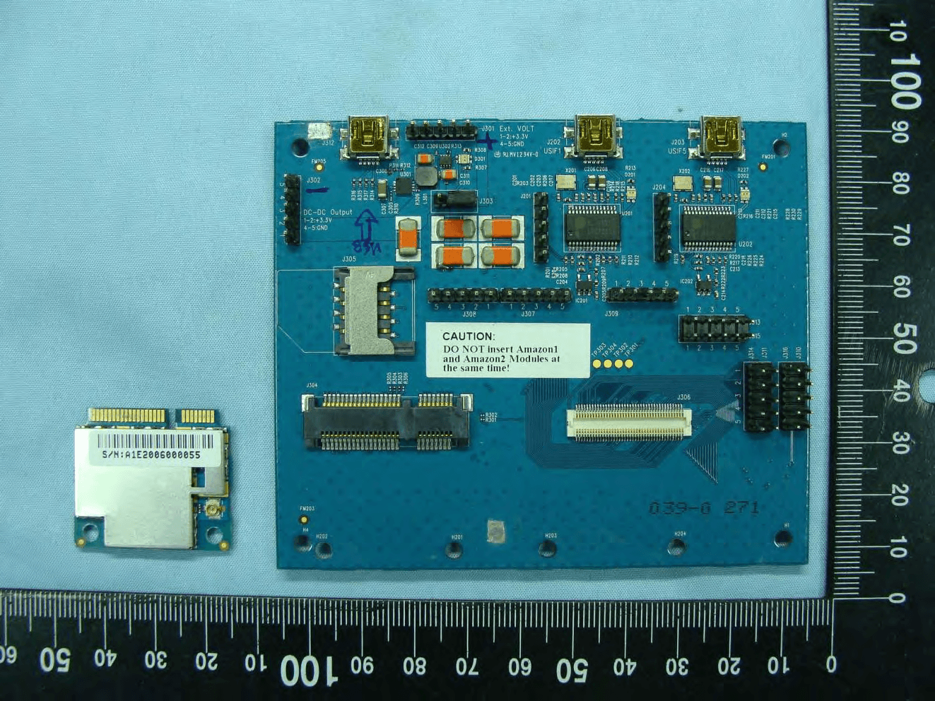
YAI1901
Aug 18, 20103.5G data card
Equipment Class
PCB - PCS Licensed Transmitter